EP1016501A1 - Hefter - Google Patents
Hefter Download PDFInfo
- Publication number
- EP1016501A1 EP1016501A1 EP97905464A EP97905464A EP1016501A1 EP 1016501 A1 EP1016501 A1 EP 1016501A1 EP 97905464 A EP97905464 A EP 97905464A EP 97905464 A EP97905464 A EP 97905464A EP 1016501 A1 EP1016501 A1 EP 1016501A1
- Authority
- EP
- European Patent Office
- Prior art keywords
- staple
- section
- frame
- mouth
- handle
- Prior art date
- Legal status (The legal status is an assumption and is not a legal conclusion. Google has not performed a legal analysis and makes no representation as to the accuracy of the status listed.)
- Withdrawn
Links
- 238000003780 insertion Methods 0.000 claims description 24
- 230000037431 insertion Effects 0.000 claims description 24
- 230000007246 mechanism Effects 0.000 claims description 5
- 238000006073 displacement reaction Methods 0.000 claims description 4
- 238000007373 indentation Methods 0.000 abstract description 8
- 238000004519 manufacturing process Methods 0.000 description 6
- 238000012856 packing Methods 0.000 description 4
- 238000005452 bending Methods 0.000 description 3
- 230000000717 retained effect Effects 0.000 description 3
- 238000012790 confirmation Methods 0.000 description 2
- 230000000994 depressogenic effect Effects 0.000 description 2
- 239000000047 product Substances 0.000 description 2
- 229910000831 Steel Inorganic materials 0.000 description 1
- 230000006835 compression Effects 0.000 description 1
- 238000007906 compression Methods 0.000 description 1
- 230000000881 depressing effect Effects 0.000 description 1
- 230000010354 integration Effects 0.000 description 1
- 230000001105 regulatory effect Effects 0.000 description 1
- 239000011347 resin Substances 0.000 description 1
- 229920005989 resin Polymers 0.000 description 1
- 238000000926 separation method Methods 0.000 description 1
- 239000010959 steel Substances 0.000 description 1
- 239000013589 supplement Substances 0.000 description 1
Images


Classifications
-
- B—PERFORMING OPERATIONS; TRANSPORTING
- B25—HAND TOOLS; PORTABLE POWER-DRIVEN TOOLS; MANIPULATORS
- B25C—HAND-HELD NAILING OR STAPLING TOOLS; MANUALLY OPERATED PORTABLE STAPLING TOOLS
- B25C5/00—Manually operated portable stapling tools; Hand-held power-operated stapling tools; Staple feeding devices therefor
- B25C5/16—Staple-feeding devices, e.g. with feeding means, supports for staples or accessories concerning feeding devices
- B25C5/1665—Staple-feeding devices, e.g. with feeding means, supports for staples or accessories concerning feeding devices with means for preventing jamming or aiding unjamming within the drive channel
-
- B—PERFORMING OPERATIONS; TRANSPORTING
- B25—HAND TOOLS; PORTABLE POWER-DRIVEN TOOLS; MANIPULATORS
- B25C—HAND-HELD NAILING OR STAPLING TOOLS; MANUALLY OPERATED PORTABLE STAPLING TOOLS
- B25C5/00—Manually operated portable stapling tools; Hand-held power-operated stapling tools; Staple feeding devices therefor
- B25C5/02—Manually operated portable stapling tools; Hand-held power-operated stapling tools; Staple feeding devices therefor with provision for bending the ends of the staples on to the work
- B25C5/0221—Stapling tools of the table model type, i.e. tools supported by a table or the work during operation
- B25C5/0242—Stapling tools of the table model type, i.e. tools supported by a table or the work during operation having a pivoting upper leg and a leg provided with an anvil supported by the table or work
Definitions
- the present invention relates to a stapler which facilitates the removal of jammed staples.
- a stapler which comprises a cover covering the staple ejecting mouth of the frame which forms the stapler.
- the cover displaces vertically on the rear surface of the frame. Staples which have become jammed are removed by vertically displacing this cover.
- the stapling operation is performed by depressing the cover downwardly.
- the cover is displaced upwardly, the staple ejecting mouth is widened and the jammed staple is removed.
- the present invention comprises a base, a frame which is provided on the base and which has a staple ejecting notch and a staple insertion mouth, an opening and closing means which partially opens and closes the staple ejecting notch and which forms a staple ejecting mouth on the staple ejecting notch in a closed position, a staple guiding means which is provided on the frame and which guides the staple towards the staple ejecting mouth from the staple insertion mouth, a staple impelling means which pushes staples guided to the staple ejecting mouth out of the frame from the staple ejecting mouth one by one in the stapling operation, and a retaining mean which retains the staple impelling means to slide freely on the end face near the staple ejecting mouth of the frame.
- the invention is characterized in that the opening and closing means is provided between the end face of the staple ejecting mouth side and the staple impelling means along the inside of the frame.
- the opening and closing means acts as a guide to guide the staple impelling means.
- the opening and closing means has a gripping section which projects outwardly from the frame so as to abut with the upper end face of the frame in the closed position.
- a notched section is provided in the direction of displacement of the opening and closing means on the end face of the staple ejecting mouth side of the frame and an engaging section is formed to engage both the notched section and the opening and closing means.
- the engaging section engages when the opening and closing means is in the closed position.
- a through hole is formed in proximity with the staple ejecting mouth on the frame.
- the staple guiding means comprises an outer guiding section which guides the staple by being adapted to the outer shape of the staple and an inner guiding section which guides the staple by being adapted to the outer shape of the staple and by engaging with the outer guiding section.
- the inner guiding section has a narrow width approximating that of the staple ejecting mouth and is formed to widen from the staple insertion mouth towards the staple ejecting mouth.
- the inner guiding section has a narrow width section having a narrow section formed in a fixed position widely from the staple insertion mouth towards the staple ejecting mouth and a wide section having a greater width than the narrow section below the fixed position.
- the outer guiding section is provided with a projection facing the narrow section of the inner guiding section.
- a handle section and an impelling section are provided.
- the handle section mounts one end to rotate freely on the frame.
- the impelling section is provided on the handle section and to pressure the staple impelling means by rotating the handle section in the direction of stapling.
- the handle section is provided with a variable length section the length of which can be varied.
- a locking mechanism is provided which fixes the handle section on the frame when rotating in a direction of stapling and which releases this fixation by a fixed operation.
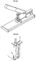
- Fig. 1 is a side sectional view of the structure of a stapler according to the present invention.
- the stapler of the present invention is formed from a base 1, a frame 2 and a handle unit 3.
- the frame 2 is mounted to rotate freely about the frame shaft 5 on a frame support plate 4 provided on the base 1.
- the frame 2 is pressed in a counter clockwise direction as shown in Fig. 1 by a spring 6 which is provided between the upper surface of the base 1 and a lower surface of an upper section of the frame 2 in the frame support plate 4.
- the frame 2 is normally supported horizontally as shown in Fig. 1 by a stopper 4B provided on the frame support plate 4.
- a bending member 9 is provided on the base 1 which bends staples ejected from the frame 2.
- the handle unit 3 is mounted to rotate freely on the frame 2 by a handle shaft 7 and is pressed in a counter clockwise direction as shown in Fig. 1 by the spring 8 which is provided between the rail cover and the lower surface of an upper section of the handle unit 3.
- the handle unit 3 is retained in an inclining state at a fixed angle as shown in Fig. 1 by the lock shaft 44 to be discussed below.
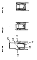
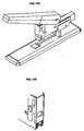
- Fig. 2 is a figure showing the detailed structure of the frame.
- Fig. 2A shows the structure of the outer frame
- Fig. 2B shows the structure of the staple impelling unit
- Fig. 2C shows the structure of the rail cover
- Fig. 2D shows the mounted position of the rail on the outer frame.
- Figs. 3A, 3B, 3C are sectional views along the lines I-I, II-II, III-III in Fig. 2A showing the structure of the frame.
- the frame 2 is formed from the outer frame 11, the staple impelling unit 12 and the rail cover 13.
- the outer frame cover 11 takes the cross sectional shape of a square shaped letter "U" as shown in Figure 3A and is formed from a bottom 11A and side walls 11B, 11C.
- a staple ejecting mouth 11b is formed in the bottom 11A to eject staples stored in the frame 2 as discussed below.
- a through hole 11p is formed in proximity to the staple ejecting mouth 11b to allow observation of the inside of the outer frame 11.
- the upper opening of the outer frame 11 acts as the staple insertion mouth 11c for storing staples 20.
- a rail 14 is provided on the bottom 11A in the longitudinal direction.
- the rail 14 is formed from a narrow section 14A which has a relatively narrow width in a range of the fixed interval L1 from the staple insertion mouth 11c and a wide section 14B the width of which is larger than the narrow section 14A and is formed in the interval L2 after the fixed interval L1 to the staple ejecting mouth 11b. Openings 14C, 14D and 14E are formed in the bottom of the rail 14. Stoppers 55, 56 and a spring mounting 57 which are formed in the bottom 11A of the outer frame 11 are inserted into the openings 14C, 14D, 14E.
- the rail 14 is adapted to slide in the longitudinal direction of the outer frame 11.
- a spring 58 which presses the rail 14 towards the staple ejecting mouth 11b is mounted on the spring mounting 14F of the rail 14 and the spring mounting 57 of the outer frame 11. In this way, when the stapling operation is performed, singly divided staples 20 are guided towards the staple ejecting mouth 11b being gripped by the pressing force of the spring 58 between the impelling blade guide 17 discussed below and the end of the rail 14.
- the displacement of the rail 14 is limited by the stoppers 55, 56 and the rail 14 does not project from the staple ejecting mouth 11b.
- a projection 11d which projects into the outer frame 11 is formed on a section facing the fixed interval L1 of the inner surface of the side walls 11B, 11C.
- the tops of many of the staples 20 as shown in Fig. 3A incline inwardly due to manufacturing errors.
- movement of staples 20 towards the staple ejecting mouth 11b and insertion of staples 20 inserted into the outer side into the frame is facilitated by the rail 14 having a narrow width in the interval L1.
- the staples 20 are guided by the narrow section 14A and the projection 11d, the staples do not wobble.
- the staples 20 guided by the inner surface of the outer frame 11 and the wide section 14B it is possible to guide staples 20 accurately while allowing for manufacturing errors in the staples 20.
- a hole 11i into which a handle shaft 7 is inserted and a variable hole 11m which is formed by the integration of the large hole 11k and the small hole 11j are formed on the side walls 11B, 11C of the outer frame 11.
- the staple impelling unit 12 is formed from a staple impelling shaft 21, a staple press 22 which is inserted into the staple impelling shaft 21, a staple press member 23 which is mounted on an end of the staple impelling shaft 21 and a spring 24 which is inserted between the staple press 22 and the staple press member 23.
- the staple press 22 is pressed in a direction away from the staple press member 23 by the spring 24 and can displace along the staple impelling shaft 21.
- a stopper 25 is mounted on another end of the staple impelling shaft 21 and in this way, separation of the staple press 22 from the staple impelling shaft 21 can be prevented.
- a fixing section 23A is formed on the staple press member 23.
- the fixing section 23A engages with the fixing section 4A (refer to Fig. 1) which is formed on the frame support plate 4.
- the staple impelling unit 12 is retained on the frame 2 since the fixing section 23A is pressed to engage with the fixing section 4A due to the pressing force of the spring 24.
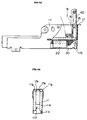
- Fig. 4 and Fig. 5 show the detailed structure in the proximity of the staple ejecting mouth 11b of the frame 2.
- Fig. 4A and Fig. 5A are partial side sectional views and Fig. 4B and Fig. 5B are rear views.
- Fig. 6 shows the structure of the guide.
- Fig. 7 shows the structure of the impelling blade guide.
- the right ends of the side walls 11B, 11C of the outer frame 11 in Fig. 4 and Fig. 5 are bent inwardly and a notch 11f and rear surface 11e are formed.
- Two indentations 11g are formed on the notch 11f.
- a guide 16 is mounted between the side surfaces 11B and 11C of the outer frame 11 by opening a fixed interval from the rear surface 11e.
- a first projection 16a is formed on the guide 16 as shown in Fig. 6A.
- a second projection 16b is formed on the first projection 16a.
- the guide 16 is fixed to the outer frame 11 by inserting the second projection 16b into the hole 11h (Fig. 2A) formed on the outer frame 11.
- the pressing blade unit 40 and the impelling blade guide 17 as discussed below are inserted into the space 15 formed between the guide 16 and the rear surface 11e of the outer frame 11.
- the impelling blade guide 17 comprises an insertion section 17a which is inserted into the space 15, a gripping section 17b which is formed on the upper end of the insertion section 17a, a fixing section 17c which is formed on the lateral end of the insertion section 17a, and an engaging section 17d which engages with the notch 11f of the outer frame 11.
- a protrusion 17e which is adapted to the indentation 11g formed on the notch 11f. is formed on the engaging section 17d.
- the impelling blade guide 17 displaces vertically as shown in Fig. 4 and Fig. 5 along the rear surface 11e of the outer frame 11 and freely opens and closes the rear surface 11e of the staple ejecting mouth 11b.
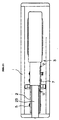
- Fig. 8 shows the structure of the handle unit 3.
- Fig. 8A is a partial side sectional view of the handle
- Fig. 8B is a plan view of the handle
- Fig. 8C is a partial side sectional view showing the structure of the handle cover
- Fig. 8D is a sectional view along the line IV-IV of Fig. 8C
- Fig. 8E is a sectional view showing the mounted position of the handle cover on the main body.
- Fig. 9 shows the assembled state of the handle unit.
- Fig. 10 shows the structure of the pressing blade unit.
- the handle unit 3 is formed from a steel handle 31 and a resin handle cover 32.
- First and second mounting holes 33 and 34 for the handle cover 32 is formed on the upper surface 31A of the handle 31.
- First and second holes 35, 36 in which the handle shaft 7 and the lock shaft 44 are inserted are formed on the side surface.
- the handle cover 32 is in the form of a square shaped letter "U".
- a projection 32A is formed on the upper inner surface of the cover 32 for fixing the handle cover 32 to the handle 31 by insertion into the mounting holes 33, 34 of the handle 31.
- Fixing sections 32B, 32C which are fixed to the handle 31 are formed in places on the end of the cover.
- the handle cover 32 is mounted on the handle 31 by fixing the fixing section 32B, 32C to the end of the handle 31 as shown in Fig. 8E.
- the mounting position of the handle cover 32 can be changed by varying in different ways mounting holes 33, 34 into which the projection 32A is inserted. In this way, it is possible to vary the length of the handle unit 3. For example, when a staple with long leg sections and a large operational force is necessarily used to staple relatively thick documents, the handle unit 3 is lengthened and it is possible to greatly increase the stapling force by such a principle.
- a bracket 38 which forms an elongated hole 37 for mounting the pressing blade unit 40 is mounted on the inner surface 31B of the handle 31.
- a spring mount 38A which mounts one end of the spring 8 is formed on the bracket 38.
- the pressing blade unit 40 comprises a main body 42 into which a pin 41 is inserted and a blade 43 which is mounted on the main body 42.
- the pressing blade unit 40 is mounted to rotate and slide freely on the elongated hole 37 of the bracket 38 due to the pin 41.
- the pressing blade unit 40 is inserted into the space 15 together with the impelling blade guide 17.
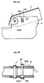
- Fig. 11, Fig. 12 and Fig. 13 are views of the mounted state of the handle on the frame.
- Fig. 12A and Fig. 13A are sectional views along the line V-V as shown in Fig. 11.
- Fig. 12B and Fig. 13B are sectional view showing the operation of the lock shaft as discussed below.
- the handle unit 3 is mounted to rotate freely on the frame 2 due to inserting the handle shaft 7 by aligning the first hole 35 of the handle unit 3 and the hole 11i of the outer frame 11.
- a lock shaft 44 which comprises a large radius section 44A and a small radius section 44B as shown in Fig. 12B and Fig.
- the large radius section 44A is separated from the variable hole 11m and only the small radius section 44B is inserted into the variable hole 11m.
- the handle unit 3 freely rotates in the range of the variable hole 11m. Upward rotation is prevented by the small radius section 44B of the lock shaft 44 abutting with the upper surface of the variable hole 11m.
- the large radius section 44A is inserted into the large hole 11k of the variable hole 11m as a result of the lock shaft 44 being pushed towards the handle unit 3 when the handle unit 3 is rotated and the large radius section 44A and the large hole 11k of the variable section 11m come into contact. In such a state, the rotation of the handle unit 3 is locked as the lock shaft 44 cannot displace in the variable hole 11m.
- the projection 32A of the handle cover 32 is inserted into the hole 33, 34 which position of the handle 31.
- the handle unit is formed by the fixing sections 32B, 32C being fixed to the end of the handle 31 and the handle cover 32 being fixed to the handle 31.
- the impelling blade guide 17 is pressed to a position in which the gripping section 17b abuts with the outer frame 11 and the protrusion 17e engages with the indentation 11g formed on the notch 11f of the outer frame 11. In this way, the rear surface 11e side of the staple ejecting mouth 11b is closed and the only opening is on the bottom side (refer to Fig. 14A).
- the staple impelling unit 12 is detached and staples 20 are inserted from the staple insertion mouth 11c of the frame 2.
- the staple impelling unit 12 is re-mounted on the frame 2 and the staples 20 are pressed towards the staple ejecting mouth 11b.
- one staple of the staples 20 is retained in a state of displacing to a position facing the staple ejecting mouth 11b.
- Fig. 3 since the end of the staples 20 is slightly inclined inwardly, insertion of the staples 20 along the rail 14 is troublesome.
- the rail 14 is formed with a narrow width near the staple insertion mouth 11c, it is possible to insert staples easily.
- the projection 11d is formed at a position facing the narrow section 14A of the rail 14 of the outer frame 11, the inserted staples 20 are not unstable. Furthermore since staple ejecting mouth 11b of the rail 14 is formed with a wide width, the staples 20 are guided accurately to the staple ejecting mouth 11b.
- Documents are inserted between the base 1 and the frame 2 and the handle unit 3 is rotated downwards.
- the frame 2 rotates in a counter clockwise direction about the frame shaft 5 as shown in Fig. 1.
- the staple ejecting mouth 11b abuts with the documents and the documents are gripped between the staple ejecting mouth 11b and the bending member 9.
- the pressing blade unit 40 displaces the space 15 downwardly, the blade 43 of the pressing blade unit 40 abuts with the staple facing the staple ejecting mouth 11b. That staple is depressed and ejected from the staple ejecting mouth 11b out of the frame 2.
- the pressing blade unit 40 displaces the elongated hole 37 of the bracket 38 which is mounted in the handle unit 3 by a pin 41.
- the pressing blade unit 40 is vertically inserted into the space 15.
- the present invention is adapted so that the impelling blade guide 17 may be pulled upwardly as shown in Fig. 14B by gripping the gripping section 17b. Since the fixing section 17c of the impelling blade guide 17 is in a state of abutment with the first projection 16a of guide 16 at this time, the impelling blade guide 17 can not detach from the outer frame 11.
- the protrusion 17e of the impelling blade guide 17 which is engaged with the indentation 11g of the notched section 11f of the outer frame 11 displaces upwardly and separates from the indentation 11g.
- the rear surface 11e side of the staple ejecting mouth 11b is opened and the staple which has become caught in the staple ejecting mouth 11b is naturally ejected from the staple ejecting mouth 11b by the compression of the rail 14 due to the spring 58.
- the impelling blade guide 17 is pressed into the space 15 and it is possible to remove the staple by the insertion section 17a pressing the staple caught in the staple ejecting mouth 11b out of the staple ejecting mouth 11b.
- a impelling blade guide 17 and a blade unit 40 are provided in the space 15 between the rear surface 11e and the guide 16.
- the stapler of the present invention is adapted so that the large diameter section 44A engages with the large diameter section 11k of the variable hole 11m. In this way, the rotation of the handle unit 3 is locked.
- a large-sized stapler is packed the handle unit creates a problem and it is necessary to fix the based 1 and the handle unit 3 by tape or string. This troublesome operation increases packing costs.
- the stapler of the present invention allows the height of the product to be reduced, as it is possible to lock the handle unit 3 when in a rotated position by pressing the lock shaft 44.
- the device is adapted to allow easy insertion of staples 20 into the frame 2 by forming a narrow section 14A and a wide section 14B on the rail 14.
- the rail 14 may be formed in a tapering shape which gradually widens towards the staple ejecting mouth 11b from the staple insertion mouth 11c.
- two mounting holes 33, 34 are formed in the handle 31 of the handle unit 3 and the length of the handle 3 may be regulated in two stages.
- three or more mounting holes may be formed on the handle 31 and the length of the handle unit 3 may be varied depending on the number of mounting holes.
- a conventional stapler is provided with an opening and closing means for removing a staple jammed in the staple ejecting mouth since the opening and closing means is provided between the staple pressing means and the staple ejecting mouth.
- the present invention forms a stapler with a more simple structure, a lower cost and a reduced number of components and number of processing steps to enable displacement of the opening and closing means.
- the opening and closing means In the closed position, since a gripping means which abuts with the upper end face of the frame, the opening and closing means need not be pressed further than the upper end face of the frame. Thus it is possible to easily perform the opening and closing operation of the opening and closing means by the provision of the gripping means.
- a through hole may be formed in proximity to the staple ejecting mouth. This through hole enables simple confirmation of the remaining number of staples and thus staples may be loaded as appropriate.
- Staples can be easily inserted into the staple guiding means as an inner guiding section which forms the stapling guiding means narrows in the proximity of the staple insertion mouth. Since the inner guiding section widens toward the staple ejecting mouth from the staple insertion mouth, it is possible to guide staples accurately and allow for manufacturing errors in the staples. Furthermore it is possible to prevent staples which are inserted into the staple guiding means from wobbling.
- the inner guiding section is formed from a narrow section and a wide section.
- the wide section prevents staples inserted into the staple guide means from wobbling.
- Staples are guided in the staple guiding means confined by the projection and the narrow inner guiding section due to the provision of a projection in a position which corresponds to the narrow section of the outer guiding section. Thus it is possible to prevent staples in the narrow section from wobbling.
- the stapler retains a compact layout as a locking mechanism is provided which locks the handle when the handle is rotated towards a stapling position.
- the present invention can reduce packing costs when packing the product.
- the present invention is a large sized stapler which allows simple removal of a staple which has become jammed in the staple ejecting mouth during empty operation.
Landscapes
- Engineering & Computer Science (AREA)
- Mechanical Engineering (AREA)
- Portable Nailing Machines And Staplers (AREA)
Applications Claiming Priority (1)
| Application Number | Priority Date | Filing Date | Title |
|---|---|---|---|
| PCT/JP1997/000720 WO1998039143A1 (en) | 1997-03-07 | 1997-03-07 | Stapler |
Publications (1)
| Publication Number | Publication Date |
|---|---|
| EP1016501A1 true EP1016501A1 (de) | 2000-07-05 |
Family
ID=14180179
Family Applications (1)
| Application Number | Title | Priority Date | Filing Date |
|---|---|---|---|
| EP97905464A Withdrawn EP1016501A1 (de) | 1997-03-07 | 1997-03-07 | Hefter |
Country Status (3)
| Country | Link |
|---|---|
| US (1) | US6179193B1 (de) |
| EP (1) | EP1016501A1 (de) |
| WO (1) | WO1998039143A1 (de) |
Cited By (2)
| Publication number | Priority date | Publication date | Assignee | Title |
|---|---|---|---|---|
| EP1454717A1 (de) * | 2003-02-25 | 2004-09-08 | Jui-Yuan Lin | Klammersetzgerät mit Sicherheitsvorrichtung zur Vermeidung des Herausspringens von Klammern aus dem Gerät |
| EP1884321A4 (de) * | 2005-05-25 | 2010-09-15 | Sebek Ltd | Klammermaschine |
Families Citing this family (11)
| Publication number | Priority date | Publication date | Assignee | Title |
|---|---|---|---|---|
| JP2002011674A (ja) * | 2000-06-27 | 2002-01-15 | Nagai Seisakusho:Kk | ステイプラーおよびステイプラー用位置決め部材 |
| JP4590694B2 (ja) * | 2000-07-14 | 2010-12-01 | マックス株式会社 | ステープラの倍力機構 |
| US6626346B2 (en) * | 2002-02-20 | 2003-09-30 | Acco Brands, Inc. | Jam clearing mechanism for a stapler |
| US6776321B2 (en) * | 2002-02-20 | 2004-08-17 | Acco Brands, Inc. | Heavy duty stapler |
| US7140526B2 (en) * | 2004-12-27 | 2006-11-28 | Plus Stationary Corporation | Stapler |
| US7334716B2 (en) * | 2005-01-26 | 2008-02-26 | Apex Mfg. Co., Ltd. | Stapler capable of cutting staple legs one after another |
| US7942298B2 (en) * | 2005-09-08 | 2011-05-17 | Acco Brands Usa Llc | Paper processing tool with force reducing drive arrangement |
| CN102554876B (zh) * | 2005-09-08 | 2014-10-29 | 阿科布兰兹美国有限责任公司 | 纸张加工处理工具的传动装置 |
| JP4752743B2 (ja) * | 2006-11-29 | 2011-08-17 | マックス株式会社 | ステープラ |
| US7963429B2 (en) * | 2007-08-21 | 2011-06-21 | William Carlton Zolentroff | Mid-zone stapler or pressing tool |
| US8122805B2 (en) * | 2007-12-12 | 2012-02-28 | Acco Brands Usa Llc | Paper processing tool with three-lever actuation |
Family Cites Families (9)
| Publication number | Priority date | Publication date | Assignee | Title |
|---|---|---|---|---|
| US2289308A (en) * | 1936-10-12 | 1942-07-07 | Lou Obstfeld | Stapling machine |
| US3076195A (en) * | 1960-12-07 | 1963-02-05 | Skrebba Werk Fa | Stapler |
| US4005812A (en) * | 1975-06-04 | 1977-02-01 | Duo-Fast Corporation | Electric fastener driving tool |
| US4520956A (en) * | 1983-04-15 | 1985-06-04 | Olave, Solozabal Y Cia., S.A. | Stapling machine |
| JPS60194483A (ja) | 1984-03-15 | 1985-10-02 | Fuji Xerox Co Ltd | 磁気記録方法 |
| JPS60194483U (ja) * | 1984-06-05 | 1985-12-25 | エルム工業株式会社 | ホツチキス |
| ATE78515T1 (de) | 1984-10-05 | 1992-08-15 | Genentech Inc | Dna, zellkulturen und verfahren zur sekretion von heterologen proteinen und periplasmische proteinrueckgewinnung. |
| JPS6334851Y2 (de) * | 1984-11-24 | 1988-09-14 | ||
| US5642849A (en) * | 1995-12-01 | 1997-07-01 | Lih Jie Industrial Co., Ltd. | Barrel unit with a removable cover plate for a nail driving gun |
-
1997
- 1997-03-07 EP EP97905464A patent/EP1016501A1/de not_active Withdrawn
- 1997-03-07 WO PCT/JP1997/000720 patent/WO1998039143A1/ja not_active Ceased
- 1997-03-07 US US09/380,689 patent/US6179193B1/en not_active Expired - Fee Related
Non-Patent Citations (1)
| Title |
|---|
| See references of WO9839143A1 * |
Cited By (2)
| Publication number | Priority date | Publication date | Assignee | Title |
|---|---|---|---|---|
| EP1454717A1 (de) * | 2003-02-25 | 2004-09-08 | Jui-Yuan Lin | Klammersetzgerät mit Sicherheitsvorrichtung zur Vermeidung des Herausspringens von Klammern aus dem Gerät |
| EP1884321A4 (de) * | 2005-05-25 | 2010-09-15 | Sebek Ltd | Klammermaschine |
Also Published As
| Publication number | Publication date |
|---|---|
| US6179193B1 (en) | 2001-01-30 |
| WO1998039143A1 (en) | 1998-09-11 |
Similar Documents
| Publication | Publication Date | Title |
|---|---|---|
| EP1016501A1 (de) | Hefter | |
| US5639007A (en) | Stapler with indicator assembly for indicating and dispensing staples of different sizes | |
| US7124924B2 (en) | Desktop stapler striker/anvil alignment system | |
| US20070034664A1 (en) | Spring-powered stapler | |
| US5497931A (en) | Stapler for dispensing staples of different sizes | |
| GB2275465A (en) | Cassettes for piles of sheets | |
| US7124561B2 (en) | Tape guide device for gardening buncher | |
| CN100349702C (zh) | 订书机的卡塞清理机构 | |
| CN112334321A (zh) | 装订夹 | |
| JP5906925B2 (ja) | 用紙処理装置 | |
| US7731071B2 (en) | Staple leg guide | |
| US7823759B2 (en) | Spring powered stapler | |
| EP0895180B1 (de) | IC-Kartenverbinder | |
| EP1884321A1 (de) | Klammermaschine | |
| US6616027B2 (en) | Stapler apparatus that removes only jammed staples | |
| JP4158682B2 (ja) | ステープラ | |
| KR20010062807A (ko) | 전동 호치키스용 카트리지 | |
| CN113316499B (zh) | 订书机 | |
| JPWO1998039143A1 (ja) | ステープラー | |
| EP1577061A1 (de) | Elektrischer Heftapparat | |
| CN115674102B (zh) | 一种平针订书机 | |
| JP6724628B2 (ja) | ステープラ | |
| JPH08174445A (ja) | ステープラー | |
| JP3099560U (ja) | 釘打ち機の空打ち防止装置 | |
| JP2024100254A (ja) | 結束機 |
Legal Events
| Date | Code | Title | Description |
|---|---|---|---|
| PUAI | Public reference made under article 153(3) epc to a published international application that has entered the european phase |
Free format text: ORIGINAL CODE: 0009012 |
|
| 17P | Request for examination filed |
Effective date: 19991007 |
|
| AK | Designated contracting states |
Kind code of ref document: A1 Designated state(s): DE FR GB NL |
|
| STAA | Information on the status of an ep patent application or granted ep patent |
Free format text: STATUS: THE APPLICATION IS DEEMED TO BE WITHDRAWN |
|
| 18D | Application deemed to be withdrawn |
Effective date: 20031001 |