EP1016579A1 - Méthode et dispositif pour programmer des transpalettes - Google Patents
Méthode et dispositif pour programmer des transpalettes Download PDFInfo
- Publication number
- EP1016579A1 EP1016579A1 EP99850216A EP99850216A EP1016579A1 EP 1016579 A1 EP1016579 A1 EP 1016579A1 EP 99850216 A EP99850216 A EP 99850216A EP 99850216 A EP99850216 A EP 99850216A EP 1016579 A1 EP1016579 A1 EP 1016579A1
- Authority
- EP
- European Patent Office
- Prior art keywords
- truck
- mode
- programming
- programming mode
- control
- Prior art date
- Legal status (The legal status is an assumption and is not a legal conclusion. Google has not performed a legal analysis and makes no representation as to the accuracy of the status listed.)
- Granted
Links
- 238000000034 method Methods 0.000 title claims abstract description 10
- 230000004913 activation Effects 0.000 claims abstract description 4
- 230000006870 function Effects 0.000 claims abstract description 4
- 230000000994 depressogenic effect Effects 0.000 description 6
- 230000000881 depressing effect Effects 0.000 description 5
- 238000012795 verification Methods 0.000 description 4
- 230000008672 reprogramming Effects 0.000 description 3
- 210000001015 abdomen Anatomy 0.000 description 2
- 230000006378 damage Effects 0.000 description 2
- 230000007257 malfunction Effects 0.000 description 2
- 208000012661 Dyskinesia Diseases 0.000 description 1
- 230000001133 acceleration Effects 0.000 description 1
- 230000003044 adaptive effect Effects 0.000 description 1
- 239000002775 capsule Substances 0.000 description 1
- 238000012790 confirmation Methods 0.000 description 1
- 230000001419 dependent effect Effects 0.000 description 1
- 238000011161 development Methods 0.000 description 1
- 230000018109 developmental process Effects 0.000 description 1
- 230000005611 electricity Effects 0.000 description 1
- 210000003811 finger Anatomy 0.000 description 1
- 230000000977 initiatory effect Effects 0.000 description 1
- 238000004519 manufacturing process Methods 0.000 description 1
- 239000012528 membrane Substances 0.000 description 1
- 230000015654 memory Effects 0.000 description 1
- 239000002184 metal Substances 0.000 description 1
- 230000007935 neutral effect Effects 0.000 description 1
- 210000003813 thumb Anatomy 0.000 description 1
Images


Classifications
-
- B—PERFORMING OPERATIONS; TRANSPORTING
- B66—HOISTING; LIFTING; HAULING
- B66F—HOISTING, LIFTING, HAULING OR PUSHING, NOT OTHERWISE PROVIDED FOR, e.g. DEVICES WHICH APPLY A LIFTING OR PUSHING FORCE DIRECTLY TO THE SURFACE OF A LOAD
- B66F9/00—Devices for lifting or lowering bulky or heavy goods for loading or unloading purposes
- B66F9/06—Devices for lifting or lowering bulky or heavy goods for loading or unloading purposes movable, with their loads, on wheels or the like, e.g. fork-lift trucks
- B66F9/075—Constructional features or details
- B66F9/0759—Details of operating station, e.g. seats, levers, operator platforms, cabin suspension
-
- B—PERFORMING OPERATIONS; TRANSPORTING
- B62—LAND VEHICLES FOR TRAVELLING OTHERWISE THAN ON RAILS
- B62B—HAND-PROPELLED VEHICLES, e.g. HAND CARTS OR PERAMBULATORS; SLEDGES
- B62B3/00—Hand carts having more than one axis carrying transport wheels; Steering devices therefor; Equipment therefor
- B62B3/04—Hand carts having more than one axis carrying transport wheels; Steering devices therefor; Equipment therefor involving means for grappling or securing in place objects to be carried; Loading or unloading equipment
- B62B3/06—Hand carts having more than one axis carrying transport wheels; Steering devices therefor; Equipment therefor involving means for grappling or securing in place objects to be carried; Loading or unloading equipment for simply clearing the load from the ground
- B62B3/0612—Hand carts having more than one axis carrying transport wheels; Steering devices therefor; Equipment therefor involving means for grappling or securing in place objects to be carried; Loading or unloading equipment for simply clearing the load from the ground power operated
-
- B—PERFORMING OPERATIONS; TRANSPORTING
- B66—HOISTING; LIFTING; HAULING
- B66F—HOISTING, LIFTING, HAULING OR PUSHING, NOT OTHERWISE PROVIDED FOR, e.g. DEVICES WHICH APPLY A LIFTING OR PUSHING FORCE DIRECTLY TO THE SURFACE OF A LOAD
- B66F9/00—Devices for lifting or lowering bulky or heavy goods for loading or unloading purposes
- B66F9/06—Devices for lifting or lowering bulky or heavy goods for loading or unloading purposes movable, with their loads, on wheels or the like, e.g. fork-lift trucks
- B66F9/075—Constructional features or details
- B66F9/07568—Steering arrangements
-
- H—ELECTRICITY
- H02—GENERATION; CONVERSION OR DISTRIBUTION OF ELECTRIC POWER
- H02P—CONTROL OR REGULATION OF ELECTRIC MOTORS, ELECTRIC GENERATORS OR DYNAMO-ELECTRIC CONVERTERS; CONTROLLING TRANSFORMERS, REACTORS OR CHOKE COILS
- H02P5/00—Arrangements specially adapted for regulating or controlling the speed or torque of two or more electric motors
-
- B—PERFORMING OPERATIONS; TRANSPORTING
- B62—LAND VEHICLES FOR TRAVELLING OTHERWISE THAN ON RAILS
- B62B—HAND-PROPELLED VEHICLES, e.g. HAND CARTS OR PERAMBULATORS; SLEDGES
- B62B5/00—Accessories or details specially adapted for hand carts
- B62B5/06—Hand moving equipment, e.g. handle bars
- B62B5/063—Hand moving equipment, e.g. handle bars for low-lift hand trucks
Definitions
- the object of the invention is to define a solution to the above problem.
- the solution in accordance with the invention is that no extra equipment at all is mounted, but possibly a display that is often required for other reasons and that may be very simple.
- the programming controls are used that all trucks are equipped with anyhow.
- the control for the signal and the drive control are chosen since these controls always exist when it is the question of an electrically driven truck. In this way a total of three different signals to the electronic of the truck is obtained since the speed or drive control has signals both for forward and backward movement.
- the parameters and their settings can be indicated by a simple code on a simple but well observable display on the truck handle. Since controls are used that are there anyhow the cost increase if any will be a minimum.
- the machine should preferably have two distinct separate work modes, one for use and one for programming, where shifting can not take place with less than the truck being shut off. In this way it becomes impossible to slip over from working mode to programming mode or vice versa.
- the signal control can be depressed at the same time as the key is turned for the truck. In order to start the truck for work one can simply avoid depressing the signal control (button).
- the total cost can be kept low since the display can be arranged more or less directly in the proximity of the logic card.
- a sensor can be chosen corresponding to a certain speed forward stepping forward and another corresponding certain speed for the sensing (in this mode) so that a sufficient distance is obtained as well as a simple provision of signals to the electronic when this is in a programming mode
- programming mode not only the setting of different parameters but also function control and error searching can be included, as well as any settings or checking that is done via electronics.
- programming mode can be divided into several different modes, alternatively one can conceive that the truck apart from the work mode has several programming or electronically accessible modes, as for instance one mode for an error log.
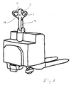
- FIG. 1 shows a tiller truck in its entirety
- fig 2 its handle seen from above
- fig 3 and 4 vertical longitudinal sections through the handle
- fig 5 one of the speed controls.
- the tiller truck shown in fig 1 includes a drive and power unit from which the load forks project.
- the large batteries of the truck are arranged as well as a driving and steering wheel that is driven by a motor that is fed with electricity via a chopper that for instance provide currents in the shape of short pulses via tyristors.
- a hydraulic pump is provided with its electrically driven motor and hydraulic valves for the lifting movements.
- a tiller 4 is further connected, that is hinged height wise but pivotable together with the wheel in the drive and power unit for steering of the truck.
- a tiller handle is fastened and normally the operator leads the truck behind himself or steers it in front of himself.
- the handle contains a supporting structure 1 provided with two grip handles 2 and is by means of bolts 3 fastened to the tiller 4 of the truck.
- On the frame 1 of the handle a control panel is fastened with four screws 6.
- the panel 5 is provided with drive controls 7 and 8 for left and right hand respectively for control of travel direction and speed by turning.
- the control panel further includes a safety control or belly-button 9, a control 10 for lifting and lowering of the forks , a control 11 for lifting and lowering of the support legs and two buttons for the horn, one for the left and one for the right hand.
- a safety control or belly-button 9 On the top side the handle is further provided a display 13 and on the bottom side there is keyboard 14 for authority verification.
- the drive controls 7 and 8 has the shape that is shown in fig 5 and differ from conventional drive controls by a downwards facing only slightly curved side 31.
- the operator can when he walks forwards with the truck following after him turn the palm of the hand upwards with the index finger in contact with the downwards facing only slightly curved side of the control, while the thumb may grip into the upper recess 32 turned towards the operator.In this way the ergonomics and the possibility of the operator to vary the manner in which the drive controls are actuated improve, so that the comfort is increased at the same time as the risk of wear damages is reduced.
- the drive controls 8 and 7 for right and left hand respectively are connected to an axle 15 journaled in a lower bowl shaped part of the control panel 5.
- an arm 16 is arranged provided with a magnet 17 in the outer end.
- this magnet 17 is swung upwards or downwards from the neutral rest position dependent on desired direction of movement and speed respectively.
- the magnet that moves in a vertical plane at this sweeps along a curved double path of separate Hall sensors 18 arranged on a printed circuit 19.
- Via a serial cable 31 the printed circuit card is in contact with the drive and power unit of the truck.
- the printed circuit card is in the proximity of the speed control arranged in a narrow vertical receiving space or slot 20 in the bottom part of the housing and is in this way well protected, while the magnet moves on the outside of the slit wall, the magnet or any of the other moveable parts can thus not harm the Hall sensors or the printed circuit card even at greater play.
- the magnet field however has no difficulty in reaching through the walls of the receptacle and influence the Hall-elements.
- the Hall elements 18 serve as sensors or switches and the further forward (towards the truck) arranged logic is programmed so that it via the serial cable 31 and an electronically controlled chopper between battery and drive motor can control a successive increasing feed of more drive power at increased deflection of the drive control.
- the axle is further influenced by a spring device that when uninfluenced return the speed control to its 0-position. Since the Hall sensors 18 are arranged in double rows a large number of individual control levels are obtained (nine in each direction).
- the possibility is obtained to have many regulator steps at a low cost and it is easy to adapt the truck speed to the walking velocity of individual operators.
- the steps are smaller at low speeds than those at the higher speeds.
- the electronics is programmed to give a stepless increase, which is obtained by a successive and stepless increase to this value as the control is turned to the next step.
- This adaptive ramping may to its inclination be controlled by the time that passes between the activation of the different sensors at increase and decrease. Although this leads to a delay corresponding to the time between the reaction of these sensors this time is entirely negligible in relation to the slowness of the truck due to its weight.
- Hall-elements for contact free control one can consider the use of photosensitive elements together with light guides or reflectors and light emitting diodes or some other light source.
- the belly or security button has as its purpose to prevent the operator from being squeezed between the truck and a wall. Should this occur and the belly button is pushed in this is on an inwardly extending arm 21 provided with a magnet 22 that at this movement is moved so that it will influence one or several of the Hall elements that belong to the speed control, the magnet 22 however being located on the other side of the circuit card and its respective slot in relation to the magnet of the speed control.
- the magnet is as is apparent in level with the Hall-element that corresponds to the next fastest speed away from the operator, that is movement in the fork direction.
- the logic of the printed circuit card is at this programmed to activate an anti squeeze operation where the truck moves away from the operator until the button is released and has returned to its initial position.
- the logic is further so programmed that if it detects a sensor fault that could mean that the sensor or sensors that are to react on a pushing of the belly-button might be non-functioning further use is blocked, or only allowed with limitations, as for instance that the truck can only be driven with a reduced speed and/or that the truck can not be driven towards the operator.
- controls located on top of the handle are provided with arms 23, 24 and magnets 25, 26 so that a tilting movement result in Hall-elements 27-30 being influenced initiating movements up and down for forks and support legs respectively.
- the use of Hall elements on the printed circuit card is particularly simple to arrange since the controls are located centrally in the handle in the same manner as the printed circuit card. If so desired one could consider also to arrange the signal controls with an extension and a magnet for a corresponding activation but in the shown case the signal controls are conventional electric contacts and connected by means of electric leads. Since the sensors belonging to the different movement controls are constituted by Hall elements sitting directly on the printed circuit card the possibility of electromagnetic pulses coming from the outside to interfere will become very small since the leads are short and centrally placed and also can be metal enclosed.
- the slot or channel 20 receiving the printed circuit card 19 in the panel housing is narrow where the Hall sensors are situated to allow magnet influence for respective control but is widened in the end facing the truck. In this wider end the capsules containing the processors, memories etc are arranged, as well as the connections to the serial cable 31, keyboard and display.
- the display 13 arranged on top of the control panel 5 is connected to the printed circuit card 19.
- the display is used at malfunction control and parameter setting without external means or additionally on the truck arranged means, but solely with the controls that the truck is normally provided with.
- one of the signal buttons is depressed at the same time as the truck is turned on via the authority verification described in more detail below alternatively with a key. This result in the logic of the truck entering into what we could call a check mode with all working functions inactive.
- An E is shown on the display corresponding to an Error log mode.
- a continued depressing result in the display of a P corresponding to parameter setting mode and a releasing of the signal button causes it to stay in the shown mode.
- Examples of parameters etc that may be adjusted are allowed acceleration and retardation, height and load limitations, what one wants to receive warnings about, as battery voltage, load weight, height indication, if the indication is to be in kilograms, pounds, meters, feet etc.
- the shift back from the error mode or parameter setting mode to drive mode is by turning the machine off. By not depressing any of the signal buttons at the starting the machine starts in drive mode with the possibly new parameter settings.
- a keyboard is arranged for authority verification and starting and turning off of the truck instead of by means of a key.
- the keyboard is connected to the printed circuit card and arranged on the bottom of the housing of the control panel bottom part.
- the chassis of the handle is here provided with a corresponding recess so that the keys can be actuated. In this way the keyboard will at the same time be recessed and well protected by the sturdy chassis.
- the key board includes figure keys and a green key for start and a red key for stopping. If one wishes to enter Error log Mode, parameter setting mode or some other mode where the truck is inactivated one of the signal buttons is depressed at the same time as the green button is depressed or after entered authority verification code.
- the signal buttons are easy to reach even with the handle turned upward since they are located on the side of the control panel.
- the keys of the keyboard may be provided with light emitting diodes that are lit when they have been depressed so that a receipt is obtained for the depressing, alternatively a row of light emitting diodes may be used as confirmation.
- the keys may be so called touch-keys or membrane keys.
- the invention is not limited to the above embodiment but may be varied within the frame of the inventive thought.
Landscapes
- Engineering & Computer Science (AREA)
- Transportation (AREA)
- Structural Engineering (AREA)
- Mechanical Engineering (AREA)
- Geology (AREA)
- Life Sciences & Earth Sciences (AREA)
- Civil Engineering (AREA)
- Power Engineering (AREA)
- Chemical & Material Sciences (AREA)
- Combustion & Propulsion (AREA)
- Control Of Position, Course, Altitude, Or Attitude Of Moving Bodies (AREA)
- Lifting Devices For Agricultural Implements (AREA)
- Agricultural Machines (AREA)
Applications Claiming Priority (2)
| Application Number | Priority Date | Filing Date | Title |
|---|---|---|---|
| SE9804596 | 1998-12-30 | ||
| SE9804596A SE518961C2 (sv) | 1998-12-30 | 1998-12-30 | Förfarande och anordning för programmering av truckar |
Publications (2)
| Publication Number | Publication Date |
|---|---|
| EP1016579A1 true EP1016579A1 (fr) | 2000-07-05 |
| EP1016579B1 EP1016579B1 (fr) | 2008-12-10 |
Family
ID=20413907
Family Applications (1)
| Application Number | Title | Priority Date | Filing Date |
|---|---|---|---|
| EP99850216A Expired - Lifetime EP1016579B1 (fr) | 1998-12-30 | 1999-12-27 | Méthode et dispositif pour programmer des transpalettes |
Country Status (3)
| Country | Link |
|---|---|
| EP (1) | EP1016579B1 (fr) |
| DE (1) | DE69940050D1 (fr) |
| SE (1) | SE518961C2 (fr) |
Cited By (5)
| Publication number | Priority date | Publication date | Assignee | Title |
|---|---|---|---|---|
| EP2468862A1 (fr) | 2010-12-23 | 2012-06-27 | Qiagen GmbH | Procédé et kit permettant le traitement d'échantillons biologiques inclus dans de la cire |
| EP2508463A1 (fr) | 2011-04-09 | 2012-10-10 | Jungheinrich Aktiengesellschaft | Elément d'actionnement pour un chariot de manutention |
| WO2013083260A1 (fr) | 2011-12-06 | 2013-06-13 | Qiagen Gmbh | Récupération d'une phase aqueuse comprenant des biomolécules à partir d'un mélange multiphasique |
| DE102014212086A1 (de) | 2014-06-24 | 2015-12-24 | Jungheinrich Aktiengesellschaft | Eingabeeinrichtung für ein Fahrzeug, insbesondere ein Flurförderzeug |
| FR3029863A1 (fr) * | 2014-12-15 | 2016-06-17 | Manitou Bf | Procede d'activation d'un chariot de manutention a timon orientable |
Citations (2)
| Publication number | Priority date | Publication date | Assignee | Title |
|---|---|---|---|---|
| EP0360870A1 (fr) | 1988-02-19 | 1990-04-04 | Kabushiki Kaisha Toyoda Jidoshokki Seisakusho | Dispositif de commande et d'affichage pour chariot elevateur a fourche electrique sur accumulateurs |
| US5687081A (en) * | 1994-12-30 | 1997-11-11 | Crown Equipment Corporation | Lift truck control system |
Family Cites Families (2)
| Publication number | Priority date | Publication date | Assignee | Title |
|---|---|---|---|---|
| DE4128306A1 (de) * | 1991-08-27 | 1993-03-04 | Leonische Drahtwerke Ag | Bedienungseinrichtung fuer peripherie-einrichtungen und stellantriebe in kraftfahrzeugen |
| DE19603648A1 (de) * | 1996-02-01 | 1997-08-07 | Linde Ag | Vorrichtung zur Ansteuerung des Antriebes eines Fahrzeuges |
-
1998
- 1998-12-30 SE SE9804596A patent/SE518961C2/sv not_active IP Right Cessation
-
1999
- 1999-12-27 EP EP99850216A patent/EP1016579B1/fr not_active Expired - Lifetime
- 1999-12-27 DE DE69940050T patent/DE69940050D1/de not_active Expired - Lifetime
Patent Citations (2)
| Publication number | Priority date | Publication date | Assignee | Title |
|---|---|---|---|---|
| EP0360870A1 (fr) | 1988-02-19 | 1990-04-04 | Kabushiki Kaisha Toyoda Jidoshokki Seisakusho | Dispositif de commande et d'affichage pour chariot elevateur a fourche electrique sur accumulateurs |
| US5687081A (en) * | 1994-12-30 | 1997-11-11 | Crown Equipment Corporation | Lift truck control system |
Cited By (7)
| Publication number | Priority date | Publication date | Assignee | Title |
|---|---|---|---|---|
| EP2468862A1 (fr) | 2010-12-23 | 2012-06-27 | Qiagen GmbH | Procédé et kit permettant le traitement d'échantillons biologiques inclus dans de la cire |
| EP2508463A1 (fr) | 2011-04-09 | 2012-10-10 | Jungheinrich Aktiengesellschaft | Elément d'actionnement pour un chariot de manutention |
| DE102011016635A1 (de) | 2011-04-09 | 2012-10-11 | Jungheinrich Aktiengesellschaft | Betätigungselement für ein Flurförderzeug |
| WO2013083260A1 (fr) | 2011-12-06 | 2013-06-13 | Qiagen Gmbh | Récupération d'une phase aqueuse comprenant des biomolécules à partir d'un mélange multiphasique |
| DE102014212086A1 (de) | 2014-06-24 | 2015-12-24 | Jungheinrich Aktiengesellschaft | Eingabeeinrichtung für ein Fahrzeug, insbesondere ein Flurförderzeug |
| FR3029863A1 (fr) * | 2014-12-15 | 2016-06-17 | Manitou Bf | Procede d'activation d'un chariot de manutention a timon orientable |
| WO2016097585A1 (fr) | 2014-12-15 | 2016-06-23 | Lmh Solutions | Procede d'activation d'un chariot de manutention a timon orientable |
Also Published As
| Publication number | Publication date |
|---|---|
| DE69940050D1 (de) | 2009-01-22 |
| SE9804596D0 (sv) | 1998-12-30 |
| EP1016579B1 (fr) | 2008-12-10 |
| SE9804596L (sv) | 2000-07-01 |
| SE518961C2 (sv) | 2002-12-10 |
Similar Documents
| Publication | Publication Date | Title |
|---|---|---|
| US6276485B1 (en) | Device at tiller truck | |
| EP1016578B1 (fr) | Dispositif de contrôle d'un chariot industriel guidé par un timon | |
| EP1346268B1 (fr) | Poignee a microprocesseur permettant de commander une machine a moteur | |
| CN101213103B (zh) | 具有成形电池的工业用车辆 | |
| JP5400442B2 (ja) | 作業用車輌 | |
| EP1016579B1 (fr) | Méthode et dispositif pour programmer des transpalettes | |
| EP1016569A2 (fr) | Clavier pour chariot élévateur | |
| EP1016580B1 (fr) | Commande pour chariot élévateur | |
| EP1024071B1 (fr) | Dispositif de commande de sécurité pour un chariot industriel guidé par un timon | |
| JP3743091B2 (ja) | フォ−クリフトの速度規制装置 | |
| EP0211379B1 (fr) | Mécanisme de détection du déplacement pour circuit hydraulique d'un élévateur à fourche | |
| US12473184B2 (en) | Multi-function user interface for a forklift | |
| EP1323615B1 (fr) | Dispositif de direction pour chariot de manutention | |
| ITMI961556A1 (it) | Dispositivo di consenso all'avviamento di una motocicletta | |
| JP7625983B2 (ja) | フォークリフト | |
| KR100322198B1 (ko) | 전동차량용모터방향제어장치 | |
| JP2988231B2 (ja) | リーチ式フォークリフトのリーチ動作規制装置 | |
| US6536552B2 (en) | Industrial truck with safety device | |
| JPH08116719A (ja) | ステアリング装置 | |
| WO2025159717A1 (fr) | Structure de pédale de chariot élévateur avec assistance par intelligence artificielle | |
| EP4590566A1 (fr) | Système et procédé d'aide au démarrage et d'identification d'option pour un opérateur | |
| HK1076794A1 (zh) | 地面输送机的控制手柄头部、地面输送机及操作该机的方法 | |
| HK40083790A (en) | Travel operation device for crawler aerial work vehicle | |
| KR101266974B1 (ko) | 콘트롤밸브의 조작레버 자동 잠금장치 | |
| HK1076794B (en) | Tiller handle for controlling functions of a truck, a truck and method of operating same |
Legal Events
| Date | Code | Title | Description |
|---|---|---|---|
| PUAI | Public reference made under article 153(3) epc to a published international application that has entered the european phase |
Free format text: ORIGINAL CODE: 0009012 |
|
| AK | Designated contracting states |
Kind code of ref document: A1 Designated state(s): DE FR GB |
|
| AX | Request for extension of the european patent |
Free format text: AL;LT;LV;MK;RO;SI |
|
| 17P | Request for examination filed |
Effective date: 20010105 |
|
| AKX | Designation fees paid |
Free format text: DE FR GB |
|
| GRAP | Despatch of communication of intention to grant a patent |
Free format text: ORIGINAL CODE: EPIDOSNIGR1 |
|
| RAP1 | Party data changed (applicant data changed or rights of an application transferred) |
Owner name: TOYOTA INDUSTRIES SWEDEN AB |
|
| GRAS | Grant fee paid |
Free format text: ORIGINAL CODE: EPIDOSNIGR3 |
|
| GRAA | (expected) grant |
Free format text: ORIGINAL CODE: 0009210 |
|
| AK | Designated contracting states |
Kind code of ref document: B1 Designated state(s): DE FR GB |
|
| REG | Reference to a national code |
Ref country code: GB Ref legal event code: FG4D |
|
| REF | Corresponds to: |
Ref document number: 69940050 Country of ref document: DE Date of ref document: 20090122 Kind code of ref document: P |
|
| PLBE | No opposition filed within time limit |
Free format text: ORIGINAL CODE: 0009261 |
|
| STAA | Information on the status of an ep patent application or granted ep patent |
Free format text: STATUS: NO OPPOSITION FILED WITHIN TIME LIMIT |
|
| 26N | No opposition filed |
Effective date: 20090911 |
|
| REG | Reference to a national code |
Ref country code: FR Ref legal event code: PLFP Year of fee payment: 17 |
|
| PGFP | Annual fee paid to national office [announced via postgrant information from national office to epo] |
Ref country code: GB Payment date: 20151223 Year of fee payment: 17 |
|
| PGFP | Annual fee paid to national office [announced via postgrant information from national office to epo] |
Ref country code: FR Payment date: 20151110 Year of fee payment: 17 |
|
| PGFP | Annual fee paid to national office [announced via postgrant information from national office to epo] |
Ref country code: DE Payment date: 20151222 Year of fee payment: 17 |
|
| REG | Reference to a national code |
Ref country code: DE Ref legal event code: R119 Ref document number: 69940050 Country of ref document: DE |
|
| GBPC | Gb: european patent ceased through non-payment of renewal fee |
Effective date: 20161227 |
|
| REG | Reference to a national code |
Ref country code: FR Ref legal event code: ST Effective date: 20170831 |
|
| PG25 | Lapsed in a contracting state [announced via postgrant information from national office to epo] |
Ref country code: FR Free format text: LAPSE BECAUSE OF NON-PAYMENT OF DUE FEES Effective date: 20170102 |
|
| PG25 | Lapsed in a contracting state [announced via postgrant information from national office to epo] |
Ref country code: GB Free format text: LAPSE BECAUSE OF NON-PAYMENT OF DUE FEES Effective date: 20161227 Ref country code: DE Free format text: LAPSE BECAUSE OF NON-PAYMENT OF DUE FEES Effective date: 20170701 |