EP1016771A2 - Explosionsschutzfenster - Google Patents
Explosionsschutzfenster Download PDFInfo
- Publication number
- EP1016771A2 EP1016771A2 EP99309792A EP99309792A EP1016771A2 EP 1016771 A2 EP1016771 A2 EP 1016771A2 EP 99309792 A EP99309792 A EP 99309792A EP 99309792 A EP99309792 A EP 99309792A EP 1016771 A2 EP1016771 A2 EP 1016771A2
- Authority
- EP
- European Patent Office
- Prior art keywords
- glazing unit
- framework
- blast
- protective window
- clamping channel
- Prior art date
- Legal status (The legal status is an assumption and is not a legal conclusion. Google has not performed a legal analysis and makes no representation as to the accuracy of the status listed.)
- Withdrawn
Links
- 230000001681 protective effect Effects 0.000 title description 5
- 239000011521 glass Substances 0.000 claims abstract description 22
- 239000000463 material Substances 0.000 claims abstract description 20
- 239000000853 adhesive Substances 0.000 claims abstract description 8
- 230000001070 adhesive effect Effects 0.000 claims abstract description 8
- 239000011347 resin Substances 0.000 claims abstract description 7
- 229920005989 resin Polymers 0.000 claims abstract description 7
- 230000003014 reinforcing effect Effects 0.000 claims abstract description 4
- 238000013016 damping Methods 0.000 claims description 6
- 229910052751 metal Inorganic materials 0.000 claims description 3
- 239000002184 metal Substances 0.000 claims description 3
- 230000002093 peripheral effect Effects 0.000 claims description 3
- 238000007688 edging Methods 0.000 claims description 2
- 150000003377 silicon compounds Chemical class 0.000 claims description 2
- 239000007788 liquid Substances 0.000 description 6
- 238000010276 construction Methods 0.000 description 5
- 239000000565 sealant Substances 0.000 description 5
- 238000000605 extraction Methods 0.000 description 4
- 239000007789 gas Substances 0.000 description 4
- 238000007789 sealing Methods 0.000 description 4
- 230000000717 retained effect Effects 0.000 description 3
- 230000000694 effects Effects 0.000 description 2
- 239000002360 explosive Substances 0.000 description 2
- 230000014759 maintenance of location Effects 0.000 description 2
- 229910000838 Al alloy Inorganic materials 0.000 description 1
- 208000027418 Wounds and injury Diseases 0.000 description 1
- 238000009833 condensation Methods 0.000 description 1
- 230000005494 condensation Effects 0.000 description 1
- 230000006378 damage Effects 0.000 description 1
- 230000001934 delay Effects 0.000 description 1
- 238000001035 drying Methods 0.000 description 1
- 238000004880 explosion Methods 0.000 description 1
- 238000001125 extrusion Methods 0.000 description 1
- 238000011049 filling Methods 0.000 description 1
- 239000012530 fluid Substances 0.000 description 1
- 239000012634 fragment Substances 0.000 description 1
- 238000009432 framing Methods 0.000 description 1
- 231100001261 hazardous Toxicity 0.000 description 1
- 208000014674 injury Diseases 0.000 description 1
- 238000000034 method Methods 0.000 description 1
- 239000004033 plastic Substances 0.000 description 1
- 239000004417 polycarbonate Substances 0.000 description 1
- 229920000515 polycarbonate Polymers 0.000 description 1
- 238000003908 quality control method Methods 0.000 description 1
- 238000000926 separation method Methods 0.000 description 1
- 238000005549 size reduction Methods 0.000 description 1
Images



Classifications
-
- E—FIXED CONSTRUCTIONS
- E06—DOORS, WINDOWS, SHUTTERS, OR ROLLER BLINDS IN GENERAL; LADDERS
- E06B—FIXED OR MOVABLE CLOSURES FOR OPENINGS IN BUILDINGS, VEHICLES, FENCES OR LIKE ENCLOSURES IN GENERAL, e.g. DOORS, WINDOWS, BLINDS, GATES
- E06B3/00—Window sashes, door leaves, or like elements for closing wall or like openings; Layout of fixed or moving closures, e.g. windows in wall or like openings; Features of rigidly-mounted outer frames relating to the mounting of wing frames
- E06B3/54—Fixing of glass panes or like plates
- E06B3/5454—Fixing of glass panes or like plates inside U-shaped section members
-
- B—PERFORMING OPERATIONS; TRANSPORTING
- B32—LAYERED PRODUCTS
- B32B—LAYERED PRODUCTS, i.e. PRODUCTS BUILT-UP OF STRATA OF FLAT OR NON-FLAT, e.g. CELLULAR OR HONEYCOMB, FORM
- B32B17/00—Layered products essentially comprising sheet glass, or glass, slag, or like fibres
- B32B17/06—Layered products essentially comprising sheet glass, or glass, slag, or like fibres comprising glass as the main or only constituent of a layer, next to another layer of a specific material
- B32B17/10—Layered products essentially comprising sheet glass, or glass, slag, or like fibres comprising glass as the main or only constituent of a layer, next to another layer of a specific material of synthetic resin
- B32B17/10005—Layered products essentially comprising sheet glass, or glass, slag, or like fibres comprising glass as the main or only constituent of a layer, next to another layer of a specific material of synthetic resin laminated safety glass or glazing
-
- B—PERFORMING OPERATIONS; TRANSPORTING
- B32—LAYERED PRODUCTS
- B32B—LAYERED PRODUCTS, i.e. PRODUCTS BUILT-UP OF STRATA OF FLAT OR NON-FLAT, e.g. CELLULAR OR HONEYCOMB, FORM
- B32B17/00—Layered products essentially comprising sheet glass, or glass, slag, or like fibres
- B32B17/06—Layered products essentially comprising sheet glass, or glass, slag, or like fibres comprising glass as the main or only constituent of a layer, next to another layer of a specific material
- B32B17/10—Layered products essentially comprising sheet glass, or glass, slag, or like fibres comprising glass as the main or only constituent of a layer, next to another layer of a specific material of synthetic resin
- B32B17/10005—Layered products essentially comprising sheet glass, or glass, slag, or like fibres comprising glass as the main or only constituent of a layer, next to another layer of a specific material of synthetic resin laminated safety glass or glazing
- B32B17/10165—Functional features of the laminated safety glass or glazing
- B32B17/10293—Edge features, e.g. inserts or holes
- B32B17/10302—Edge sealing
-
- B—PERFORMING OPERATIONS; TRANSPORTING
- B32—LAYERED PRODUCTS
- B32B—LAYERED PRODUCTS, i.e. PRODUCTS BUILT-UP OF STRATA OF FLAT OR NON-FLAT, e.g. CELLULAR OR HONEYCOMB, FORM
- B32B27/00—Layered products comprising a layer of synthetic resin
- B32B27/36—Layered products comprising a layer of synthetic resin comprising polyesters
-
- E—FIXED CONSTRUCTIONS
- E06—DOORS, WINDOWS, SHUTTERS, OR ROLLER BLINDS IN GENERAL; LADDERS
- E06B—FIXED OR MOVABLE CLOSURES FOR OPENINGS IN BUILDINGS, VEHICLES, FENCES OR LIKE ENCLOSURES IN GENERAL, e.g. DOORS, WINDOWS, BLINDS, GATES
- E06B3/00—Window sashes, door leaves, or like elements for closing wall or like openings; Layout of fixed or moving closures, e.g. windows in wall or like openings; Features of rigidly-mounted outer frames relating to the mounting of wing frames
- E06B3/54—Fixing of glass panes or like plates
- E06B3/58—Fixing of glass panes or like plates by means of borders, cleats, or the like
- E06B3/5807—Fixing of glass panes or like plates by means of borders, cleats, or the like not adjustable
-
- E—FIXED CONSTRUCTIONS
- E06—DOORS, WINDOWS, SHUTTERS, OR ROLLER BLINDS IN GENERAL; LADDERS
- E06B—FIXED OR MOVABLE CLOSURES FOR OPENINGS IN BUILDINGS, VEHICLES, FENCES OR LIKE ENCLOSURES IN GENERAL, e.g. DOORS, WINDOWS, BLINDS, GATES
- E06B5/00—Doors, windows, or like closures for special purposes; Border constructions therefor
- E06B5/10—Doors, windows, or like closures for special purposes; Border constructions therefor for protection against air-raid or other war-like action; for other protective purposes
- E06B5/12—Doors, windows, or like closures for special purposes; Border constructions therefor for protection against air-raid or other war-like action; for other protective purposes against air pressure, explosion, or gas
Definitions
- the present invention relates to a blast-protective window construction. More particularly, the invention provides improved glazing for such a window, which reduces assembly time, in some embodiments eliminates the use of liquid sealant during assembly on site, and most important - improves the resistance of the glass panels to separation from the window frame in response to a blast force.
- the window frame can be joined to the building by workmen who may be less than careful before any glass is brought to the building site, and the glass in its sub-frame is made in the factory and added shortly before completion of construction.
- a design of this type is proposed by Gebhard in US Patent no. 4,364,209. He describes a window frame having a J-shaped channel into which is inserted the glazing strip which has a flexible leg locking into the window frame.
- blast protective windows are designed to withstand explosive blast forces to a level usually determined by standards set by governments or local authorities.
- Security windows are used in buildings which may be subject to terrorist attacks, in bomb shelters, and in recent years have also come into extensive use in residential buildings provided with security rooms.
- Such rooms are part of the living quarters of a house or flat, and although reinforced to withstand a high degree of blast forces, and sealable against external gases, the general appearance of such rooms is reasonably similar to that of other rooms in the same building.
- blast protective windows are suspended from a sill frame by hinges and are designed to be openable, and when closed to be sealed against entry of gases, such sealing providing protection also against liquids.
- the present invention achieves the above objects by providing a multi-layer security glazing unit for resisting actions of force, comprising a pair of spaced-apart glass panels provided with a reinforcing resin material therebetween and sealed together along at least one common edge thereof by an adhesive material within a rigid clamping channel of substantially U-shaped cross-section.
- a blast-protective window comprising:
- a blast-protective window wherein the auxiliary backing framework and the clamping elements are each provided with a stepped surface. Upon assembly the distance between the interfacing inner surfaces of the backing framework and the clamping element supporting the faces of the glazing unit is less than the distance between the portions of the backing framework and the clamping element adjacent to the rigid clamping channel.
- the novel glazing system of the present invention serves to secure the glass sheets to a U channel, which U channel is quite easily retained in the window frame and is firmly restrained from extraction by shoulders or ledges integral to the frame.
- the primary glazing operation involving the use of a liquid sealant filling the rigid U channel and gripping the glass therein, need not be carried out at the construction site but in the factory, where such work can be better controlled and executed.
- the glass, together with its sub-frame is best transported to the building site just before the building is being completed, and is thus protected from the dangers of ongoing construction activities.
- the workmen installing the window frame in the building wall can carry out their task without concern for the glass.
- the window pane with its sub frame may be installed without requiring the use on site of liquid sealants.
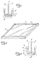
- FIG. 1 a multi-layer security glazing unit 10 configured for resisting actions of force, and retaining glass sheets in a frame under high fluid or gas pressure.
- a pair of spaced-apart glass panels 12 are provided with a reinforcing resin material 14, for example polycarbonate, therebetween.
- the panels 12 are sealed together along at least one common edge 16 thereof by an adhesive material 18, advantageously a silicon compound.
- the material 18 is contained and sets within a rigid clamping channel 20 of substantially U-shaped cross-section.
- the adhesive material 18 serves both to support the glass panels 12 in a flexible manner, and also to grip the edges of the glass panels so that retention of the channel 20 in a framework, to be described with reference to FIG.4, causes corresponding retention of the glass panels 12.
- the rigid clamping channel 20 is made of a metal, for example an aluminium alloy extrusion.
- FIG. 2 there is seen a multi-layer security glazing unit 22 wherein the surrounding common peripheral edge of the panels 12 and resin material 14, seen in FIG. 1, are sealed together by an adhesive material 18 within the clamping channel 20.
- the clamping channel 20 forms an edging frame for the unit.
- the unit 22 is advantageously factory manufactured separate from the window frame, seen in FIG. 4, in which it is to be inserted, thus saving on-site labor.
- FIG. 3 illustrates a further embodiment of a multi-layer security glazing unit 24.
- the rigid clamping channel 26 is provided with a ledge-like flange 28 projecting substantially perpendicular to the general plane of an arm 30 thereof.
- the flange 28 projects beyond an outside face of a major surface of arm 30.
- the flange 28 When assembled to a window frame, seen in FIG. 4, the flange 28 underrides an abutment surface 32 provided along an inner side of a window framework 34. Thus the flange 28 reinforces securing of the glazing unit 24 in a window framework 34 and prevents its extraction when subjected to a blast force.
- Seen in FIG. 4 is a blast-protective window 36.
- the window 36 holds a multi-layer security glazing unit 24 as described with reference to FIG. 3.
- the window frame 34 is joined and sized to receive and surround the glazing unit 24.
- the window frame 34 comprises a main framework 38 of vertical and horizontal elements extending in a general plane of a substantially vertical orientation.
- the framework 38 has an arm 40 for sealing against a further framework or wall.
- the window frame 34 includes an auxiliary backing framework 42 also extending in a general plane of a substantially vertical orientation.
- the auxiliary backing framework 42 partly protrudes across the opening defined by the main framework for at least indirectly supporting a first face 44 of the glazing unit 24.
- the main framework 38 and auxiliary framework 42 are integrally joined, typically being extruded as a single profile.
- the two frameworks 38, 42 together have a substantially L-shaped cross-section along the surrounding common edge thereof.
- a clamping element 46 is adapted to be attached by means of screws 48 to the main framework 38.
- a surface thereof 50 is adjacent to, and supports a second face 52 of the glazing unit 24 via an elastomeric seal strip 54.
- a sloping non-structural cover 56 hides the screws 48.
- Sealing the window 36 against dangerous gases and liquids is preferably achieved by use of an elastomeric seal 58 positioned between an inwardly facing surface 60 of the auxiliary backing framework 42 and the first face 44 of glazing unit 24. Similarly, sealing is further improved by use of the elastomeric seal 54.
- FIG. 5 there is depicted a blast-protective window 62 wherein the surface 63 of the clamping element 64 adjacent to seal element 54 is provided with a flange-like projection 66. This serves for abutting an upper surface 68 of an arm 70 of the rigid clamping channel 26.
- an elastomeric damping material 72 is introduced between the upper surface 68 and projection 66 of the clamping element 64.
- the elastomeric damping material 72 serves to evenly spread the stress of a blast force on the glass panels of the glazing unit 24 and thus increase the blast pressure which can be successfully withstood by the window 62.
- FIG. 6 shows an arrangement similar to that shown in FIG. 5 being used on the other side of the glass.
- a blast-protective window 74 has an inwardly facing surface 76 of an auxiliary backing framework 78. It is provided with a flange-like projection 80 for abutting an upper surface 82 of an arm 30 of the rigid clamping channel 26.
- an elastomeric damping material 84 is introduced between the upper surface 82 and projection 80.
- FIG. 7 illustrates a further embodiment of a blast-protective window 86.
- the auxiliary backing framework 88 and the clamping element 90 are each provided with a stepped surface 92, 94. Upon assembly, there is a distance "A" between the interfacing inner surfaces 96, 98 of the backing framework 88 and the clamping element 90 supporting the faces of the glazing unit 10.
- a space 100 is provided between the stepped surfaces 92,94 and the rigid clamping channel 20.
- the space 100 allows a small amount of initial movement as the unit 10 attempts to disengage as result of blast forces, before offering resistance, thus helping in dissipating stress concentrations before the channel 20 locks against the stepped surfaces 92,94.
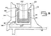
- Seen in Fig. 8 is a further embodiment of a blast-protective window 102.
- the rigid clamping channel 104 is provided with a flexible ledge-like flange 106 projecting substantially perpendicular to the general plane of an arm 114, and beyond an outside face of a major surface of this arm.
- Flange 106 underrides and contacts an abutment surface 32 provided along an inner side of the auxiliary backing framework 108.
- Flange-like projections 110, 112 attached respectively to the inwardly facing surface of clamping element 64 and to inwardly facing surface of the auxiliary backing framework 108 are spaced about 2 to 10 mm apart from the upper surfaces 114 of the arms 116 of the rigid clamping channel 104.
- the flexible ledge-like flange 106 bends to absorb a part of the glazing unit energy. After a short movement the glazing unit 120 is halted by abutment with flange-like projections 110, 112.
- Fig. 9 Seen in Fig. 9 is an embodiment generally similar to that seen in Fig. 8 and in which similar reference numerals have been used to identify similar parts.
- flange-like projections 117 and 119 project inwardly and with a downward slant from the inwardly facing surface of clamping element 64 and the inwardly facing surface of auxiliary backing framework 108 and have extremities 122 sloping downwards towards the channel 104.
- the upper surfaces 121 of the arms 114 and 116 of the rigid clamping channel 104 are provided with a slope complimentary to the underside of projections 117 and 119 to effect a better locking interengagement therebetween, wherein the upper outer corner 123 of said surfaces 121 are nestled in the angled juncture 124 between arm 119 and auxiliary backing framework 108 and arm 117 and clamping element 64. .
- Said unit can further be provided with damping material 118 which becomes trapped and compressed upon upper movement of the channel 104.
- Fig. 10 shows an embodiment 126 similar to that seen previously in Fig. 2.
- the channels are four discreet members 128, which together surround major portions of the common peripheral edges of said resin and panels 12, however do not extend to the corners thereof.
- the channels 128, being shorter than those shown in Fig. 2, are easier to assemble, as there is no need for corner joints, and the channels do not need to be accurately cut to length.
Landscapes
- Engineering & Computer Science (AREA)
- Civil Engineering (AREA)
- Structural Engineering (AREA)
- Securing Of Glass Panes Or The Like (AREA)
Applications Claiming Priority (2)
| Application Number | Priority Date | Filing Date | Title |
|---|---|---|---|
| IL12742498 | 1998-12-07 | ||
| IL12742498A IL127424A (en) | 1998-12-07 | 1998-12-07 | Blast protective window |
Publications (2)
| Publication Number | Publication Date |
|---|---|
| EP1016771A2 true EP1016771A2 (de) | 2000-07-05 |
| EP1016771A3 EP1016771A3 (de) | 2001-08-22 |
Family
ID=11072231
Family Applications (1)
| Application Number | Title | Priority Date | Filing Date |
|---|---|---|---|
| EP99309792A Withdrawn EP1016771A3 (de) | 1998-12-07 | 1999-12-06 | Explosionsschutzfenster |
Country Status (3)
| Country | Link |
|---|---|
| US (1) | US6581342B1 (de) |
| EP (1) | EP1016771A3 (de) |
| IL (1) | IL127424A (de) |
Cited By (5)
| Publication number | Priority date | Publication date | Assignee | Title |
|---|---|---|---|---|
| WO2008023158A3 (en) * | 2006-08-21 | 2008-10-02 | Brades John | Frame assembly for sheet material |
| WO2008139201A3 (en) * | 2007-05-15 | 2009-06-04 | Ingersoll Rand Security Techno | Blast door |
| CN102733513A (zh) * | 2012-06-20 | 2012-10-17 | 曾红 | 一种玻璃隔墙的下端固定装置 |
| EP2287433A3 (de) * | 2009-08-07 | 2013-12-04 | Trueform Engineering Limited | Explosionsfestes Glasiersystem |
| GB2585618A (en) * | 2018-05-03 | 2021-01-20 | Brett Martin Ltd | Glazing profiles |
Families Citing this family (26)
| Publication number | Priority date | Publication date | Assignee | Title |
|---|---|---|---|---|
| MXPA03011621A (es) * | 2001-06-15 | 2004-06-30 | Sashlite Llc | Bastidor de ventana de multihoja de vidrio integrada y metodo para fabricar el bastidor de ventana de multihoja de vidrio integrado. |
| US6829868B1 (en) * | 2003-01-14 | 2004-12-14 | International Aluminum Corporation | Glazing pane installation |
| US6789362B1 (en) * | 2003-01-29 | 2004-09-14 | Iradj Hessabi | Thermally controlled window tinting |
| US20050138889A1 (en) * | 2003-04-24 | 2005-06-30 | Lawrence Biebuyck | Curtain wall system with enhanced resistance to blast forces |
| US7389617B2 (en) * | 2003-04-29 | 2008-06-24 | Oldcastle Windows, Inc. | Building curtain wall sealing system |
| US7631471B2 (en) * | 2003-05-02 | 2009-12-15 | Oldcastle Glass Engineered Products, Inc. | Method and apparatus for moisture collection and diversion in curtain walls |
| US7818934B2 (en) * | 2004-10-18 | 2010-10-26 | Oldcastle Glass Engineered Products, Inc. | Curtain wall mullion sealing bridge |
| US20060080936A1 (en) * | 2004-10-18 | 2006-04-20 | Dooley David M | Method of manufacturing reinforced structures |
| US20060201078A1 (en) * | 2005-03-10 | 2006-09-14 | Westcrowns Inc. | Reinforced glass and method |
| US7845124B1 (en) * | 2005-04-29 | 2010-12-07 | American Development Group International, Llc | Window frame |
| US20080282626A1 (en) * | 2005-05-26 | 2008-11-20 | Powers Jr John | Window Sill |
| US9097058B2 (en) | 2010-02-24 | 2015-08-04 | Ricon Corp. | Bonded-in, anti-vandalism transit vehicle window system |
| EP2434249B1 (de) * | 2010-09-22 | 2013-05-01 | ISOCLIMA S.p.A. | Panzerglasscheibe mit Randverstärkung |
| US9163400B2 (en) | 2011-02-23 | 2015-10-20 | Oldcastle Buildingenvelope, Inc. | Method and system for improved curtain wall sealing |
| CN103781979A (zh) * | 2011-05-13 | 2014-05-07 | 旭硝子法国简易股份公司 | 将风撑装配在玻璃墙壁上的装配系统 |
| US9163449B2 (en) * | 2011-07-01 | 2015-10-20 | Andersen Corporation | Laminated glass retention system |
| CN106068359B (zh) * | 2013-12-03 | 2018-06-12 | Aja企业私人有限公司 | 面板组件 |
| EP3092361A4 (de) * | 2014-01-10 | 2017-10-25 | Insite Manufacturing Pty Ltd | Paneel und paneelanordnung |
| US9453362B2 (en) * | 2014-11-25 | 2016-09-27 | West Tampa Glass Company | Shelter curtain wall system |
| SG11201805439RA (en) * | 2016-01-12 | 2018-07-30 | Agc Glass Europe | Frameless glass door or window arrangement with drip groove |
| US10934743B2 (en) * | 2016-10-21 | 2021-03-02 | C.R. Laurence Co., Inc. | Taper-loc system improvements |
| DE202017101856U1 (de) * | 2017-03-30 | 2017-04-27 | Häfele Berlin Gmbh & Co Kg | Rückwand-Einsteckkeil |
| CN107035956B (zh) * | 2017-04-19 | 2023-04-14 | 正安鑫旺钢化玻璃有限公司 | 一种具有防护功能的钢化玻璃支架 |
| JP7063740B2 (ja) * | 2018-06-18 | 2022-05-09 | 日本板硝子株式会社 | 真空ガラスパネル |
| US12240202B2 (en) | 2019-08-07 | 2025-03-04 | Andersen Corporation | Laminated glass retention system |
| US12215541B2 (en) | 2020-07-09 | 2025-02-04 | Andersen Corporation | System and methods of attaching retention members to insulating glazing units |
Citations (3)
| Publication number | Priority date | Publication date | Assignee | Title |
|---|---|---|---|---|
| US4006569A (en) | 1975-10-02 | 1977-02-08 | Monarch Mirror Door Co., Inc. | Panel mounting |
| US4364209A (en) | 1980-08-20 | 1982-12-21 | Gebhard Paul C | Window glazing system |
| US5356675A (en) | 1992-12-28 | 1994-10-18 | Unger Frederick C | Glazing system |
Family Cites Families (16)
| Publication number | Priority date | Publication date | Assignee | Title |
|---|---|---|---|---|
| US2094435A (en) * | 1935-09-06 | 1937-09-28 | Pittsburgh Plate Glass Co | Double window construction |
| US2264176A (en) * | 1940-02-06 | 1941-11-25 | Pittsburgh Plate Glass Co | Multiple glazed unit |
| US2525717A (en) * | 1945-01-08 | 1950-10-10 | Reuben E Ottenheimer | Multiwalled structure |
| US3889434A (en) * | 1974-04-12 | 1975-06-17 | Lyle N Shelver | Thermal glass structural device |
| GB1541682A (en) * | 1975-04-22 | 1979-03-07 | Yoshida Kogyo Kk | Gasket construction |
| US4295305A (en) * | 1975-06-09 | 1981-10-20 | Shelver Lyle N | Thermal glass structure and method for forming same |
| FR2355986A1 (fr) * | 1976-06-24 | 1978-01-20 | Saint Gobain | Perfectionnement au montage des vantaux vitres |
| JPS54171239U (de) * | 1978-05-24 | 1979-12-04 | ||
| DE3117103A1 (de) * | 1981-04-30 | 1982-11-18 | Messerschmitt-Bölkow-Blohm GmbH, 8000 München | Ausbildung von fahrzeug-fenstereinfassungen |
| US4669241A (en) | 1986-01-28 | 1987-06-02 | Thermatic Glass, Inc. | Thermal insulated and shock resistant window assembly |
| US4636421A (en) * | 1986-02-27 | 1987-01-13 | Creation Windows, Inc. | Frame with decorative trim strip |
| US4984402A (en) | 1989-09-29 | 1991-01-15 | Omniglass Ltd. | Sash window arrangement |
| US5778629A (en) * | 1995-09-28 | 1998-07-14 | Howes; Stephen E. | Impact resistant window |
| US5806256A (en) * | 1996-03-26 | 1998-09-15 | Byrne; John F. | Modular glazing system |
| DE19632616B4 (de) * | 1996-08-13 | 2004-10-07 | Saint-Gobain Sekurit Deutschland Gmbh & Co. Kg | Seitenaufprallschutz für Fahrzeuginsassen |
| US5853828A (en) * | 1996-12-24 | 1998-12-29 | Solutia Inc. | Safety glass structure resistant to extreme wind and impact |
-
1998
- 1998-12-07 IL IL12742498A patent/IL127424A/xx not_active IP Right Cessation
-
1999
- 1999-12-06 EP EP99309792A patent/EP1016771A3/de not_active Withdrawn
- 1999-12-07 US US09/455,809 patent/US6581342B1/en not_active Expired - Fee Related
Patent Citations (3)
| Publication number | Priority date | Publication date | Assignee | Title |
|---|---|---|---|---|
| US4006569A (en) | 1975-10-02 | 1977-02-08 | Monarch Mirror Door Co., Inc. | Panel mounting |
| US4364209A (en) | 1980-08-20 | 1982-12-21 | Gebhard Paul C | Window glazing system |
| US5356675A (en) | 1992-12-28 | 1994-10-18 | Unger Frederick C | Glazing system |
Cited By (11)
| Publication number | Priority date | Publication date | Assignee | Title |
|---|---|---|---|---|
| WO2008023158A3 (en) * | 2006-08-21 | 2008-10-02 | Brades John | Frame assembly for sheet material |
| JP2010501747A (ja) * | 2006-08-21 | 2010-01-21 | イアン、ハニー | シート材料用フレーム組立体 |
| RU2466263C2 (ru) * | 2006-08-21 | 2012-11-10 | Брэйдз Джон | Рамный узел для листового материала |
| CN101558214B (zh) * | 2006-08-21 | 2013-05-29 | 约翰·布雷德斯 | 用于片材的框架组件 |
| AU2007287427B2 (en) * | 2006-08-21 | 2013-10-03 | Brades, John | Frame assembly for sheet material |
| US8752354B2 (en) | 2006-08-21 | 2014-06-17 | Ian HONEY | Frame assembly for sheet material |
| WO2008139201A3 (en) * | 2007-05-15 | 2009-06-04 | Ingersoll Rand Security Techno | Blast door |
| EP2287433A3 (de) * | 2009-08-07 | 2013-12-04 | Trueform Engineering Limited | Explosionsfestes Glasiersystem |
| CN102733513A (zh) * | 2012-06-20 | 2012-10-17 | 曾红 | 一种玻璃隔墙的下端固定装置 |
| GB2585618A (en) * | 2018-05-03 | 2021-01-20 | Brett Martin Ltd | Glazing profiles |
| GB2585618B (en) * | 2018-05-03 | 2021-08-18 | Brett Martin Ltd | Glazing profiles |
Also Published As
| Publication number | Publication date |
|---|---|
| IL127424A (en) | 2000-11-21 |
| US6581342B1 (en) | 2003-06-24 |
| IL127424A0 (en) | 1999-10-28 |
| EP1016771A3 (de) | 2001-08-22 |
Similar Documents
| Publication | Publication Date | Title |
|---|---|---|
| US6581342B1 (en) | Blast protective window | |
| US6088979A (en) | Frame for supporting an auxiliary glazing and method for installing the improved frame | |
| AU2007287427B2 (en) | Frame assembly for sheet material | |
| US5185979A (en) | Assembling sheets of glass to metal structures | |
| US4464874A (en) | Window unit | |
| US8413403B2 (en) | Curtainwall system | |
| CA2497233C (en) | Window assembly having an outer sash frame supporting a removable inner sub-sash frame bonded to insulated glass panels | |
| US10125539B2 (en) | Door with impact resistant light | |
| US3807107A (en) | Closure spacer member and method of erecting a fixed frame assembly | |
| WO1991014067A1 (en) | Construction for mounting windows, doors and the like | |
| JPH11324498A (ja) | 窓 | |
| GB2227270A (en) | Frame for door or window | |
| EP0261907A2 (de) | Fenster | |
| JPH10131365A (ja) | カーテンウォールのパネル保持部構造 | |
| JP4139271B2 (ja) | サッシの取付方法 | |
| US20230220667A1 (en) | Lightweight thermal barrier panel and anchor system for building envelopes and method for installing the same | |
| JPH1061081A (ja) | 表面カバー材を備えたパネル保持部構造 | |
| US20050138883A1 (en) | Frame and panel assembly | |
| CA1298454C (en) | Curtain wall assembly | |
| WO2001098617A1 (en) | A blast-protective window construction | |
| JP2542629Y2 (ja) | カーテンウオールの窓におけるガラス間口の雨切り装置 | |
| JP2816638B2 (ja) | フラットカーテンウォール | |
| JP3058596B2 (ja) | 建具枠及び建具枠の取付け方法 | |
| GB2236789A (en) | Security clip for retaining a glazing member in a frame | |
| NO310482B1 (no) | Bygningselement innbefattende et tetningsmembran, selve tetningsmembranen, samt en fremgangsmåte for fremstilling av etbygningselement |
Legal Events
| Date | Code | Title | Description |
|---|---|---|---|
| PUAI | Public reference made under article 153(3) epc to a published international application that has entered the european phase |
Free format text: ORIGINAL CODE: 0009012 |
|
| AK | Designated contracting states |
Kind code of ref document: A2 Designated state(s): AT BE CH CY DE DK ES FI FR GB GR IE IT LI LU MC NL PT SE |
|
| AX | Request for extension of the european patent |
Free format text: AL;LT;LV;MK;RO;SI |
|
| PUAL | Search report despatched |
Free format text: ORIGINAL CODE: 0009013 |
|
| AK | Designated contracting states |
Kind code of ref document: A3 Designated state(s): AT BE CH CY DE DK ES FI FR GB GR IE IT LI LU MC NL PT SE |
|
| AX | Request for extension of the european patent |
Free format text: AL;LT;LV;MK;RO;SI |
|
| 17P | Request for examination filed |
Effective date: 20020104 |
|
| AKX | Designation fees paid |
Free format text: AT BE CH CY DE DK ES FI FR GB GR IE IT LI LU MC NL PT SE |
|
| 17Q | First examination report despatched |
Effective date: 20030901 |
|
| STAA | Information on the status of an ep patent application or granted ep patent |
Free format text: STATUS: THE APPLICATION IS DEEMED TO BE WITHDRAWN |
|
| 18D | Application deemed to be withdrawn |
Effective date: 20040113 |