EP1017149A2 - Nichtisoliertes verkabeltes System mit zwei Betriebsarten für tragbare schnurlose Elektrowerkzeuge - Google Patents
Nichtisoliertes verkabeltes System mit zwei Betriebsarten für tragbare schnurlose Elektrowerkzeuge Download PDFInfo
- Publication number
- EP1017149A2 EP1017149A2 EP99310302A EP99310302A EP1017149A2 EP 1017149 A2 EP1017149 A2 EP 1017149A2 EP 99310302 A EP99310302 A EP 99310302A EP 99310302 A EP99310302 A EP 99310302A EP 1017149 A2 EP1017149 A2 EP 1017149A2
- Authority
- EP
- European Patent Office
- Prior art keywords
- power
- tool
- voltage
- corded
- power supply
- Prior art date
- Legal status (The legal status is an assumption and is not a legal conclusion. Google has not performed a legal analysis and makes no representation as to the accuracy of the status listed.)
- Granted
Links
Images


Classifications
-
- B—PERFORMING OPERATIONS; TRANSPORTING
- B25—HAND TOOLS; PORTABLE POWER-DRIVEN TOOLS; MANIPULATORS
- B25F—COMBINATION OR MULTI-PURPOSE TOOLS NOT OTHERWISE PROVIDED FOR; DETAILS OR COMPONENTS OF PORTABLE POWER-DRIVEN TOOLS NOT PARTICULARLY RELATED TO THE OPERATIONS PERFORMED AND NOT OTHERWISE PROVIDED FOR
- B25F5/00—Details or components of portable power-driven tools not particularly related to the operations performed and not otherwise provided for
- B25F5/02—Construction of casings, bodies or handles
-
- H—ELECTRICITY
- H02—GENERATION; CONVERSION OR DISTRIBUTION OF ELECTRIC POWER
- H02J—ELECTRIC POWER NETWORKS; CIRCUIT ARRANGEMENTS OR SYSTEMS FOR SUPPLYING OR DISTRIBUTING ELECTRIC POWER; SYSTEMS FOR STORING ELECTRIC ENERGY
- H02J7/00—Circuit arrangements for charging or discharging batteries or for supplying loads from batteries
- H02J7/70—Circuit arrangements for charging or discharging batteries or for supplying loads from batteries characterised by the mechanical construction
- H02J7/731—Circuit arrangements for charging or discharging batteries or for supplying loads from batteries characterised by the mechanical construction specially adapted for holding portable devices containing batteries
-
- H—ELECTRICITY
- H02—GENERATION; CONVERSION OR DISTRIBUTION OF ELECTRIC POWER
- H02J—ELECTRIC POWER NETWORKS; CIRCUIT ARRANGEMENTS OR SYSTEMS FOR SUPPLYING OR DISTRIBUTING ELECTRIC POWER; SYSTEMS FOR STORING ELECTRIC ENERGY
- H02J7/00—Circuit arrangements for charging or discharging batteries or for supplying loads from batteries
- H02J7/865—Battery or charger load switching, e.g. concurrent charging and load supply
-
- H—ELECTRICITY
- H01—ELECTRIC ELEMENTS
- H01H—ELECTRIC SWITCHES; RELAYS; SELECTORS; EMERGENCY PROTECTIVE DEVICES
- H01H9/00—Details of switching devices, not covered by groups H01H1/00 - H01H7/00
- H01H9/02—Bases, casings, or covers
- H01H9/06—Casing of switch constituted by a handle serving a purpose other than the actuation of the switch, e.g. by the handle of a vacuum cleaner
- H01H2009/065—Battery operated hand tools in which the battery and the switch are directly connected
-
- H—ELECTRICITY
- H01—ELECTRIC ELEMENTS
- H01H—ELECTRIC SWITCHES; RELAYS; SELECTORS; EMERGENCY PROTECTIVE DEVICES
- H01H9/00—Details of switching devices, not covered by groups H01H1/00 - H01H7/00
- H01H9/02—Bases, casings, or covers
- H01H9/06—Casing of switch constituted by a handle serving a purpose other than the actuation of the switch, e.g. by the handle of a vacuum cleaner
-
- H—ELECTRICITY
- H01—ELECTRIC ELEMENTS
- H01H—ELECTRIC SWITCHES; RELAYS; SELECTORS; EMERGENCY PROTECTIVE DEVICES
- H01H9/00—Details of switching devices, not covered by groups H01H1/00 - H01H7/00
- H01H9/52—Cooling of switch parts
-
- H—ELECTRICITY
- H02—GENERATION; CONVERSION OR DISTRIBUTION OF ELECTRIC POWER
- H02H—EMERGENCY PROTECTIVE CIRCUIT ARRANGEMENTS
- H02H7/00—Emergency protective circuit arrangements specially adapted for specific types of electric machines or apparatus or for sectionalised protection of cable or line systems, and effecting automatic switching in the event of an undesired change from normal working conditions
- H02H7/08—Emergency protective circuit arrangements specially adapted for specific types of electric machines or apparatus or for sectionalised protection of cable or line systems, and effecting automatic switching in the event of an undesired change from normal working conditions for dynamo-electric motors
- H02H7/085—Emergency protective circuit arrangements specially adapted for specific types of electric machines or apparatus or for sectionalised protection of cable or line systems, and effecting automatic switching in the event of an undesired change from normal working conditions for dynamo-electric motors against excessive load
- H02H7/0852—Emergency protective circuit arrangements specially adapted for specific types of electric machines or apparatus or for sectionalised protection of cable or line systems, and effecting automatic switching in the event of an undesired change from normal working conditions for dynamo-electric motors against excessive load directly responsive to abnormal temperature by using a temperature sensor
Definitions
- the present invention relates generally to electrically operated power tools and in particular, to portable hand-held power tools which can alternatively operate in either a cordless mode from a self-contained power source or a corded mode from a conventional AC/DC generator power source.
- Electrically operated devices that function in a cordless mode typically include a housing which has a chamber for receiving and retaining a removable battery pack.
- the battery pack completely encloses one or more cells and provides the necessary DC power for operation of the device.
- cordless electrically powered devices have included relatively low power devices such as shavers and hand-held calculators.
- improvements in battery technology have led to the development of batteries that store more energy and are capable of driving higher power devices.
- These devices include for example, portable hand-held power tools and appliances operating at power levels from 50 watts up to hundreds of watts.
- a hand-held power tool is typically powered by a battery pack that comprises a number of batteries connected in series. To provide the higher power levels required by high power devices an increased number of batteries are connected in series resulting in higher input voltages and battery pack volumetric requirements.
- Cordless power devices permit work operations to be performed in areas where a conventional AC power source is not available or inconvenient to use.
- the effective charge capacity of the battery pack and the availability of replacement battery packs limit the use of cordless devices. When the battery pack is discharged, it must be recharged or replaced with a fully charged pack.
- Both batteries and battery chargers are expensive in comparison to the power device for which they are intended. Batteries for high power applications cost approximately 30% of the cost of the applicable power device. Additional batteries are required to permit cordless mode operation while a battery is recharged and to replace dead batteries. High power levels drawn from batteries during operation of the power tool, the depth of discharge of the battery, the number of charge/discharge cycles, and the speed with which a battery is recharged all contribute to shortening the usable lifetime of a battery.
- Fast chargers can cost more than the power tool or appliance that is powered by the battery. There are two basic types of battery chargers, trickle chargers and fast chargers. Trickle chargers are significantly less expensive than fast chargers, however a trickle charger requires approximately 1/2 day to recharge a battery pack. A fast charger on the other hand can recharge a battery pack within approximately one hour. Therefore, a trade off must be made between using a trickle charger with a large number of battery packs versus using a costly fast charger with very few replacement battery packs.
- corded AC converter module that is connected to an AC power source and designed to replace the battery pack.
- the corded converter module converts power from the AC source to a regulated low-voltage DC level that is usable by the motor of the power device.
- Such a device allows a tool operator to use the tool in either the cordless battery mode or the corded AC mode as needed.
- the availability of such device enables the operator of a cordless tool to complete a project when the battery pack has been discharged, or to continue to use the tool while the battery pack is charging and a fully charged backup battery pack is unavailable.
- the need for extra battery packs is minimized.
- the prior art design of a corded converter module is constrained by a number of factors such as the physical envelope, the required output power level, the voltage conversion ratio of the converter, safety requirements to protect the operator from electrical shock, and cost.
- the envelope of the corded converter module must conform to the envelope of the battery pack with which it is interchangeable. With the increased volumetric requirements for battery packs there is increased volume available for housing a corded converter.
- the power output level of the converter is directly related to the available volume within the container envelope. The power output levels adequate to drive power devices such as hand held power tools are possible within the physical envelope of commercial battery packs.
- the voltage conversion ratio of the converter is the ratio between the rectified input voltage and the converter output voltage. The converter output voltage is set to a level roughly equivalent to the battery voltage.
- the safety regulations are typically met by isolating the operator of the power device from the AC power source.
- Commercially available systems meet the safety regulations by employing a high frequency power transformer to isolate the output power of the converter module from the relatively high voltage AC input power source.
- Power transformers are custom devices that are expensive and bulky in comparison with the other electronic devices of the converter module. Attempts to minimize costs of corded converter modules have concentrated on optimizing the output power capability of the converter module for a given power device. By designing the converter module for the minimum output power required to satisfactorily drive the power device, lower cost electronic components can be chosen for the converter.
- corded power tools already faced with the cost of battery packs and battery chargers must also invest in expensive corded converter modules for their power tools.
- Attempts to minimize the cost of corded conversion modules have been constrained by the cost of using transformer isolation to meet the government safety requirements.
- Obtaining further cost reductions by reducing the output power level of a corded converter module would result in under-powered power devices. While the prior art can be used to provide corded converter modules for a handheld power tool, it has not proven capable of providing low cost modules that are convenient to use.
- a DC low voltage power tool DC power tool operable in a preselected voltage range.
- the tool comprises an electrical system for operating the tool.
- a pre-defined electrical interface of the tool is provided for mechanically and electrically mating with a power supply module.
- the electrical system of the tool is enclosed in a double insulated tool casing to prevent the conduction of electrical charge from the interior to the exterior of the power tool.
- the power tool is preferably selectively powered by either a battery power supply module connectable to the electrical interface of the tool or a nonisolated corded power supply module connectable to the electrical interface of the tool.
- the corded non-isolated power supply module converts the relatively high voltage line power from the source of electric power to a DC voltage in the preselected voltage range suitable for powering the low-voltage DC power tool.
- a corded/cordless system for power tools comprises a low-voltage DC power tool operable in a preselected voltage range.
- the power tool has a casing that is double insulated from the electrical system of the tool to prevent the conduction of electrical charge from the interior to the exterior of the power tool.
- the tool further comprises a corded non-isolated power supply module mechanically and electrically configured to connect to a source of relatively high voltage electric power and to mate with the low-voltage DC power tool.
- the corded non-isolated power supply module is adapted to convert the relatively high voltage line power from the source of electric power to a DC voltage in the preselected voltage range suitable for powering the low-voltage DC power tool.
- the system may further comprise a cordless battery power supply module to power the tool.
- the module is preferably mechanically and electrically configured to mate with the low-voltage DC power tool and to contain a battery assembly having a DC voltage in the preselected voltage range suitable for powering the low-voltage DC power tool.
- the power tool is configured to receive power from either the corded non-isolated power supply module or the battery power supply module.
- the power tool pre-defined interface has a physical envelope configuration to accept either of the corded non-isolated converter power supply module and the cordless battery power supply module.
- the power tool pre-defined interface may further include first electrical tool terminals for providing electrical connection with battery terminals associated with the cordless battery power supply module and second electrical tool terminals for providing electrical connection with converter terminals associated with the corded non-isolated converter power supply module.
- the converter terminals preferably comprises output terminals located within recesses formed in the non-isolated converter power supply module.
- the second electrical tool terminals are adapted to extend into the recesses to make electrical connection with the converter output terminals when the non-isolated converter power supply module is connected to the tool housing.
- the converter output terminals are preferably female connectors and the second tool terminals are preferably male connectors.
- the battery terminals are preferably male connectors and the first tool terminals are preferably female connectors.
- the power tool pre-defined interface preferably further comprises a latch for releasably securing either of the corded non-isolated converter power supply module and the cordless battery power supply module.
- a method for supplying power to a DC power tool operable in a preselected voltage range.
- the power tool has exposed surfaces and an internal electrical system including a motor and a control circuit for controlling the operation of the motor.
- the method comprises at least the following steps. First, the exposed surfaces of the DC power tool are double insulated from the electrical system to prevent the surfaces from becoming electrically energized. Second, a corded non-isolated power supply module is connected to the power tool and to a source of relatively high voltage electric power. Third, the power from the source of relatively high voltage electric power is converted to a DC voltage that is not transformer isolated from the source of relatively high voltage electric power and is within the pre-selected voltage range suitable for powering the DC power tool. Finally, the DC power tool is powered with the corded non-isolated power supply module.
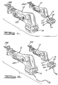
- a dual-mode portable power tool 12 according to the present invention is shown. While the present invention is shown and described with a reciprocating saw 12, it will be appreciated that the particular tool is merely exemplary and could be a circular saw, a drill, or any other similar portable power tool constructed in accordance with the teachings of the present invention.
- the power tool 12 includes a DC motor (not shown) that is adapted in the preferred embodiment to be powered by a source having a relatively low voltage such as a 24 volt DC source, although other low voltage DC systems, such as 12 volts or 18 volts, could be used.
- a source having a relatively low voltage such as a 24 volt DC source, although other low voltage DC systems, such as 12 volts or 18 volts, could be used.
- the power tool 12 is powered by a removable battery power supply module 14.
- the power tool 12 may be powered from a source having a relatively high voltage such as common 115 volt AC line power via an AC/DC power converter module 16 which is adapted to be plugged into the power tool in place of the battery power supply module 14.
- the power tool 12 may be powered from a relatively high voltage DC generator (not shown) via the AC/DC power converter module 16.
- relatively high voltage means voltages of 40 volts or greater and the term relatively low voltage means voltages less than 40 volts.
- the rechargeable battery power supply module 14 of the present invention is illustrated to generally include a housing 18, a battery 20 which in the exemplary embodiment illustrated is a 24 volt nickelcadmium battery, and a battery pack terminal block 22.
- the upper portion 25 of the housing 18 is formed to include a pair of guide rails 24.
- the guide rails 24 are adapted to be slidably received into cooperating channels 13 (Fig. 1) formed in a housing 14 of the tool 12.
- the upper portion 25 of the housing 18 further defines a recess 26.
- the recess 26 is adapted to receive a latch (not shown) carried by the housing of the tool 12.
- the latch is conventional in construction and operation and is spring biased to a downward position so as to engage the recess 26 upon insertion of the rechargeable battery power supply module 14. Removal of the battery power supply module 14 is thereby prevented until the spring bias of the latch is overcome in a conventional manner insofar as the present invention is concerned.
- the battery pack terminal block 22 comprises a main body portion 28 constructed of rigid plastic or other suitable material and a plurality of blade-type terminals 30.
- the battery pack terminal block 22 includes four blade terminals 30. Two of the blade terminals 30 comprise the positive and negative terminals for the battery 20.
- a third terminal 30 may be used to monitor the temperature of the battery 20 and a fourth terminal may be used to identify the battery type (e.g., 24 volt NiCad).
- a pair of holes 32 are formed in the two guide rails 24 in the upper portion 25 of the battery pack housing 18 on either side of the row of blade terminals 30. The function of these holes is described below.
- the terminal block 34 of the power tool 12 is shown.
- the main body of the tool terminal block 34 is also constructed of a rigid plastic material and is formed with a row of four U-shaped guideways 36 guiding the four corresponding blade terminals 30 of the battery power supply module 14 when the battery pack is inserted into the tool 12.
- Located within the guideways 36 are female connectors 38 that are adapted to engage and make electrical contact with the blade terminals 30 of the battery power supply module 14.
- tool terminal block 34 shown is designed to accommodate four female connectors for each of the four battery pack blade terminals 30, only two female connectors 38 adapted to engage the positive and negative blade terminals 30 of the battery power supply module 14 are used in the tool terminal block 34, as the remaining two battery pack blade terminals 30 are only used when recharging the battery power supply module 14.
- positive and negative male terminals 40 are also connected to the positive and negative female terminals 38 in the tool terminal block 34 that project through openings 42 in the terminal block on either side of the row of guideways 36. As will subsequently be discussed below, the male positive and negative terminals 40 are used to electrically connect the tool 12 to the AC/DC converter module 16.
- the interface between the battery terminal block 22 and the tool terminal block 34 is illustrated.
- the main body portion of the tool terminal block 34 includes a pair of laterally spaced rails 44 that are adapted to be received within the grooves 46 provided in the battery pack housing 18 immediately below the guide rails 24. Further insertion of the battery power supply module 14 onto the tool 12 results in the positive and negative blade terminals 30 of the battery power supply module 14 passing through the openings in the U-shaped guideways 36 and engaging the female connectors 38 in the tool terminal block 34.
- the male positive and negative terminals 40 from the tool terminal block 34 simultaneously project into the openings 32 formed in the rails 24 on the upper portion 25 of the battery pack housing 18, but do not make electrical contact with any terminals in the battery power supply module 14.
- the remaining two blade terminals 30 from the battery terminal block 22 project into empty guideways 36 in the tool terminal block 34.
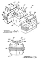
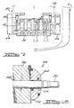
- the AC/DC converter module 16 is adapted to convert 115 volts AC house current to 24 volts DC.
- the housing 48 of the converter module 16 in the preferred embodiment is configured to be substantially similar to the housing 18 of the battery power supply module 14.
- the housing 48 includes first and second clam shell halves joined at a longitudinally extending parting line.
- An upper portion 50 of the housing 48 includes a pair of guide rails 52 similar to those of the battery power supply module 14 for engaging the channels 13 in the tool housing.
- the upper portion 50 also defines a recess (not shown) which includes a latch (not shown) for preventing the inadvertent removal of the converter module 16.
- the housing 48 also defines a recess 51 in which a fan 45 is adapted for providing cooling airflow to the converter module 16. Attached to the fan 45 is a fan cover 47 for preventing foreign objects from impeding the operation of the fan 45. Within the housing 48 several heatsinks 43 provide heat spreading and cooling for selected power converter components.
- the converter module 16 includes a pair of female terminals 54 that are adapted to receive the male terminals 40 of the tool terminal block 22.
- the guide rails 52 on the upper portion 50 of the converter housing 48 are adapted to engage the laterally spaced rails 44 on the tool terminal block 34 as the converter module 16 is installed on the tool 12 to ensure proper alignment between the female connectors 54 of the converter module 16 and the male connectors 40 of the tool 12.
- the female terminals 54 are recessed within the upper portion 50 of the housing 48 of the converter module 16 to meet safety requirements.
- the female terminals 54 are recessed within the housing 48 of the converter module 16 by at least 8mm. 115 volt AC power is converted to 24 volt DC power by the converter module 16 and delivered to the tool 12 through the female terminals 54.
- the female terminals 38 of the tool terminal block 34 are electrically inoperative.
- the presently preferred embodiment of the AC/DC power converter module 16 is a fixed-frequency, non-isolated, buck-derived topology; however, the principles of the invention can be extended to variable-frequency converters and topologies other than buck-derived, such as Cük and flyback converters.
- the power converter module 16 is designed to convert an unregulated AC voltage to a regulated DC voltage that is usable by the power tool 12.
- the converter module 16 can convert an input of 120 volts, 60 Hz AC to any low-level DC voltage less than 42 volts that is required by the power tool 12, such as 24 volts DC.
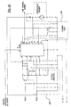
- the power converter module 16 includes a fuse 101 in series with diode bridge 102.
- a power plug and cord (refer to Fig 2) connect from fuse 101 to the other input of diode bridge 102.
- the output of diode bridge 102 is applied between high side line 104 and an inrush limiter 103 connected to ground reference line 106.
- the rectified output voltage of diode bridge 102 is filtered by the input capacitor 108.
- the resulting filtered voltage is nominally 165 volts DC.
- the input capacitor 108 connects to the drains of parallel power MOSFETs 110a and 110b that act as a voltage controlled switch. When MOSFETs 110a and 110b are in the ON state the impedance between the drain and source is low.
- MOSFETs 110a and 110b connect to the junction of output inductor 112 and the cathode of free-wheeling output diode 114.
- the other side of output inductor 112 connects to output capacitor 116.
- Current sense resistor 118 connects between the output capacitor 116 and the anode of the freewheeling diode 114.
- the anode of output diode 114 also connects to ground reference line 106.
- the voltage across output capacitor 116 is applied to the output of power converter module 16 across outputs VOUTHI 120 and VOUTLO 122, which connect to the pair of female terminals 54.
- Fan 123 is connected in parallel with output capacitor 116.
- Diode bridge 102, MOSFET 110, and free-wheeling output diode 114 all mount on heat sinks that provide heat spreading and a thermal path for dissipated power.
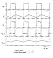
- FIGS 8 and 10 illustrate the circuitry that provides control and protection functions for power converter module 16 which includes voltage regulated power supply 124, PWM control 126, voltage feedback 128, current limit 130, and temperature sense 134.
- the voltage regulated power supply 124 connects across input capacitor 108 to provide a low power, regulated low voltage output to supply power to the internal circuitry of power converter module 16.
- the regulated low voltage output as well as the remainder of the internal circuitry is referenced to ground reference line 106.
- VOUTHI 120 connects to voltage feedback 128 which connects to PWM control 126.
- the current sense resistor 118 connects to current limit 130 which also is connected to temperature sense 134.
- the output of current limit 130 connects to PWM control 126.
- the arrangement of components that comprise voltage regulated power supply 124, PWM control 126, voltage feedback 128, current limit 130, and temperature sense 134 are well known in the art.
- Figures 9 and 10 illustrate the circuitry that provides the power conversion function for power converter module 16 which includes high voltage driver 132 and power stage components.
- the output of PWM control 126 connects to high voltage driver 132 which level shifts the output of PWM control 126 to drive the gates of MOSFETs 110a and 110b.
- the arrangement of components that comprise high voltage driver 132 are well known in the art.
- an SGS-Thomson L6381 high-side driver 172 with associated components comprises the high voltage driver 132.
- other circuit configurations for level-shifting the PWM output are within the scope of the invention, such as discrete component configurations and Motorola high-side driver chips.
- the power plug and cord are connected to an AC power source.
- the AC voltage is rectified by diode bridge 102 and applied across input capacitor 108.
- Current from the AC source surges as it flows through fuse 101, inrush limiter 103, diode bridge 102, and begins to charge input capacitor 108.
- the magnitude of the surge in current is limited to a safe level by the action of the inrush limiter 103 which is a high impedance initially, but rapidly changes to a low impedance.
- the inrush limiter 103 consists of a triac 152 in parallel with a resistor 150 that is triggered by current flowing through output inductor 112.
- the triac 152 remains OFF until the output of PWM control 126 becomes active driving the MOSFETs 110a and 110b to the ON state, at which time current flowing through output inductor 112 couples through a sense winding of inductor 112 to trigger the triac ON.
- the PWM control 126 in the present embodiment is a Texas Instruments TL494 with the associated components as depicted in Figure 10. There are numerous other control chips which could be used, such as UC1845 and SG1625.
- the output of PWM control 126 is disabled until the regulated output of voltage regulated power supply 124 exceeds 6.4 volts, at which time soft-start mode is enabled. Prior to the beginning of soft-start the oscillator of PWM control 126 begins to operate.
- the present embodiment switches at a fixed frequency of 40 kHz, although higher or lower frequencies are within the scope of the invention.
- the PWM control 126 output is a low-voltage square-wave signal having a variable pulse-width, where the pulse-width is adjusted to maintain a regulated output voltage at outputs VOUTHI 120 and VOUTLO 122.
- the pulse-width of the PWM control 126 output is initially zero, gradually increasing to a steady-state value that results in the output voltage being regulated at a desired voltage.
- the duration of soft-start mode is controlled by the selection of component values in PWM control 126 and is well known in the art. The purpose of soft-start is to limit the current and voltage stress of the power converter module 16 components during the time period when output capacitor 116 is being charged up to its nominal steady-state value.
- the feedback network in the present embodiment is a lag-lead-lag-lead configuration with well known design requirements to maintain a stable operation of power converter module 16.
- the output from PWM control 126 which is level-shifted by the high voltage driver 132 repetitively drives the MOSFETs 110a and 110b into an ON state and an OFF state at the switching frequency.
- the negative voltage across inductor 112 causes current through inductor 112 to decrease at a linear rate.
- the current again splits between VOUTHI 120 and output capacitor 116 with the DC component flowing through VOUTHI 120 and the AC component substantially flowing through output capacitor 116.
- the current returning from load 121 flows from VOUTLO 122 through current sense resistor 118 and free-wheeling output diode 114, thereby completing the current path.
- the MOSFETs 110a and 110b remain in the OFF state for the remainder of the cycle time period.
- the output of PWM control 126 is level-shifted by high voltage driver 132 in order to drive power MOSFETs 110a and 110b to either the ON state or the OFF state.
- the PWM control 126 output voltage, vpwm transitions low which causes the output of driver 172 to transition high, thus biasing the base emitter junction of PNP transistor 178 turning it OFF.
- NPN transistor 174 turns ON.
- NPN transistor 174 and resistors 176a and 176b into the gates of power MOSFETs 110a and 110b charging up the internal gate-source capacitance, raising the MOSFETs 110a and 110b gate voltage, vg, above ground before returning from the sources of MOSFETs 110a and 110b to filter capacitor 168.
- the increasing voltage across the gate-source of MOSFETs 110a and 110b causes the MOSFETs 110a and 110b to begin to turn ON, causing the source voltage of MOSFETs 110a and 110b to increase from minus one volt relative to ground reference line 106 to a value approaching the value of voltage across input capacitor 108 and additionally causing the MOSFETs 110a and 110b gate voltage, vg, to increase to the value of voltage across input capacitor 108 plus the MOSFETs gate-source voltage.
- the decoupling diode 166 becomes reverse biased decoupling the diode 166 from the remainuer of the high voltage driver 132.
- Filter capacitor 168 remains referenced to the source of MOSFETs 110a and 110b and thereby provides the energy required to maintain the gate-source voltage of MOSFETs 110a and 110b during the remainder of the ON state.
- the PWM control 126 output voltage, vpwm, transitions from a low to a high value to initiate the start of the OFF state.
- the high-side driver 172 inverts and level shifts the signal which causes NPN transistor 174 to turn OFF and PNP transistor 178 to turn ON.
- the energy stored in the internal gate-source capacitance of MOSFETs 110a and 110b discharges through resistor 176 and PNP transistor 178.
- the gate-source voltage of MOSFETs 110a and 110b decreases to less than approximately four volts MOSFETs 110a and 110b turn OFF. Free-wheeling diode 114 becomes active which causes the voltage at the sources of MOSFETs 110a and 110b to decrease to minus one volt.
- PWM control 126 In addition to controlling pulse width to maintain a constant output voltage, PWM control 126 also varies the pulse width in response to an output from current limit 130 to protect power converter module 16 from excessive output current loads. Output current flows through current sense resistor 118 causing a voltage to develop that is proportional to the output current. The voltage across resister 118 is compared to a reference voltage derived from the PWM control reference. When the output current is greater than a pre-determined maximum level the output of current limit 130 causes PWM control 126 to reduce the pulse width of the output. The reduced duty cycle causes the voltage at outputs VOUTHI 120 and VOUTLO 122 to decrease until the resulting output current is less than the pre-determined maximum level.
- Temperature sense 134 protects power converter module 16 from overtemperature stress of MOSFET 110 and output diode 114.
- a thermistor is employed as temperature sense 134 to monitor the temperature of heatsinks 43. If the temperature rises due to overload, debris blocking an air intake, or other fault condition, temperature sense 134 modifies the current limit reference voltage, thereby causing the PWM control 126 to generate a shorter pulse width. The shorter pulse width results in a lower output voltage and output current that corresponds to a lower overall output power. The lower output power causes a reduction in the power dissipated in the components of power converter module 16, resulting in lower component temperatures.
- the housing 201 of the power tool in the preferred embodiment is nonetheless double insulated from the electrical system of the tool.
- a relatively low voltage DC power source i.e., a DC source less than 50 volts
- the housing 201 of the power tool in the preferred embodiment is nonetheless double insulated from the electrical system of the tool.
- power tools designed to be operated by a high voltage power source such as a conventional AC or corded power tool
- cordless or DC powered tools are powered by low voltage power sources and therefore do not require such safety measures. Consequently, conventional DC powered tools do not insulate the housing from the electrical system of the tool.
- AC/DC powered devices universally employ transformers to step down the high AC voltage and thereby isolate the device from the high voltage AC power source.
- the present invention solves this dilemma by providing a relatively light weight non-isolated AC to DC converter and then constructing the DC powered tool in a manner consistent with the double insulation safety requirements of a conventional AC powered tool.
- the DC output voltage supplied to the motor of the power tool is referenced to the 115 volt AC input. Consequently, double insulation of the tool housing from the electrical system of the power tool is required.
- the power tool terminal block 34 is provided with independent male connectors 40 uniquely adapted to make electrical contact with, and thereby receive electrical power from, specially recessed female connectors 54 in the AC/DC converter module 16.
- independent male connectors 40 uniquely adapted to make electrical contact with, and thereby receive electrical power from, specially recessed female connectors 54 in the AC/DC converter module 16.
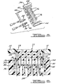
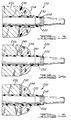
- FIGS. 12 through 17 depict the effect of employing double insulation within a motor and housing. Double insulation techniques are well known in the art. Double insulated tools are typically constructed of two separate layers of electrical insulation or one double thickness of insulation between the operator and the tool's electrical system.
- a cross-sectional view of a non-double insulated DC motor armature 200 is illustrated.
- the armature 200 consists of a shaft 202 with a core built up over it.
- the core is composed of many laminations 206 with notches along the outer periphery to hold the armature windings 204.
- a gear or chuck (not shown) is built onto the shaft at one end of the armature 206 to provide a means of transferring rotational energy to the working end 208 (see Fig.
- the armature shaft 202 could be energized through contact with end turns of the armature windings 204.
- the armature laminations 206 could be energized through contact to end turns of the armature windings 204.
- the armature 220 consists of a shaft 222 with a core built up over it.
- the core is composed of many laminations 226 with notches along the outer periphery to hold the armature windings 224.
- a chuck 228 is built onto the shaft at one end of the armature laminations 206 to provide a means of affixing a device such as a drill bit to the working end 208 (see Fig. 1) of the power tool 12.
- a molded plastic insulator 230 provides basic insulation between the armature windings 224 and the laminations 226 as well as between the shaft 222 and the windings 224.
- a press fit plastic tube insulator 232 encases the shaft 222 providing supplementary insulation to prevent the shaft from becoming energized if the basic insulation breaks down.
- a paper insulator 240 provides basic insulation between the armature windings 224 and the laminations 226.
- a second insulator 242 of double thickness, 2 mm encases the shaft 222 providing reinforced insulation, which substitutes for supplementary insulation, to prevent the shaft from becoming energized through electrical shorts to the laminations 226 or the armature windings 224.
- FIG. 15 a third method of employing double insulation of the motor armature 220 of a power tool is illustrated.
- An insulator 250 of either paper or molded plastic provides basic insulation between the armature windings 224 and the laminations 226.
- An in situ molded thermoset plastic insulator 252 of double thickness encases the shaft 222 providing reinforced insulation, which substitutes for supplementary insulation, to prevent the shaft from becoming energized through electrical shorts to the laminations 226 or the armature windings 224.
- a slot liner insulator 260 provides basic insulation between the armature windings 224 and the laminations 226.
- the slot liner insulator is constructed of any suitable electrical insulator material such as paper, coated paper, polyester, and vulcanized fiber. Supplementary insulation is provided by a glass reinforced polyester insulator sleeve 262 which encases the shaft 222. The insulator sleeve prevents the shaft from becoming energized if the basic insulation provided by slot liner 260 fails.
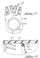
- a double insulated housing 270 of a power tool is illustrated.
- the double insulation methods employed are intended to prevent electrical energy within the housing 270 from energizing the outside surface of the housing 270.
- the housing 270 is depicted with a hypothetical metal foil covering 272 on the outside surface to simulate interaction with an operator.
- a ring terminal 274 and an insulated wire 276 that includes a conductive wire 278 and wire insulation 280. Electrical energy exists on both the ring terminal 274 and the conductive wire 278.
- Double insulation of the ring terminal 274 is provided by a double thickness, 2 mm, of housing material which serves as a reinforced insulator.
- the wire insulation 280 provides basic insulation for conductive wire 278. Supplementary insulation is provided by the housing 270 which prevents electrical energy that breaks through the wire insulation from energizing the outside surface of the housing 270.
- the power converter module 16 initially converts the low frequency AC input to a high level DC voltage, then to a high frequency voltage level that is thereafter filtered to the lower voltage supply level of power tool 12.
- the power tool employs double insulation of the motor rather than transformer isolation of the power converter 16, thereby significantly reducing the cost and weight of the power converter module 16.
- the converter module 16 is designed with a comparatively small number of components while providing an efficient conversion process. This further enhances the lightweight, compact features of the converter module 16.
- the size of the converter module 16 further permits the use of the converter in power-operated devices, such as the reciprocating saw 12, which heretofore were too small to support and contain conversion units providing power in a range of at least 50 watts and higher.
- the converter module 16 converts a low frequency, high voltage level to a low DC voltage level
- the converter can be used to convert a high DC voltage level to a low voltage DC level by applying the high DC level directly to a suitable power cord and plug that connects to the input of converter module 16.
- the power tool 12 could be operated from the high DC voltage source instead of the low DC voltage of the cells 26 and thereby conserve the charge life of the cells.
- the converter module 16 could be designed to operate from external AC power sources other than 120 volts at 60 Hz. Without departing from the spirit and scope of the invention, the converter module 16 also could be designed to provide DC output voltage levels in a range of 3.6 to 48 volts. In a particular example, the converter could be adjusted to develop a DC output of 24 volts between the outputs VOUTHI 120 and VOUTLO 122 derived from an external AC source of 220 volts at 50 Hz as applied to a suitable power plug and cord. The converter module 16 could then be used to provide inexpensive dual mode capability for power-operated devices that operate at a DC voltage supply level of 24 volts.
- the reciprocating saw 12 is merely illustrative of one example of many power-operated, cordless-mode devices that become more versatile because of the inventive cost efficient dual-mode capability.
- Other examples of power-operated cordless devices which are enhanced by the inventive concept include, but are not limited to, drills, screwdrivers, screwdriver-drills, hammer drills, jig saws, circular saws, hedge trimmers, grass shears, as well as battery-operated household products and the like.
- the present invention provides a number of advantages. More particularly, the present invention decreases costs by meeting the government safety requirements in a unique manner.
- the invention uses a double insulated casing for the power tool rather than employing transformer isolation. Eliminating the power transformer from the corded converter module significantly reduces the cost and weight of the module.
- a low cost converter module provides operators of cordless power tools the low cost option of using a corded converter module when AC power sources are available. This eliminates the cost of purchasing a separate corded power device as well as reducing the number of battery packs that must be purchased.
- Corded power converters designed without power transformers are substantially less expensive than converters designed with power transformers. Additionally, eliminating the power transformer decreases the weight of the converter resulting in improved operator comfort.
- a further advantage of the system is the low cost of providing additional tools for the system once a user has available the battery power supply module and the corded power supply module. Accordingly, additional tools compatible with the system can be acquired by purchasing the tool without any power supply module and used with the available battery power supply module and corded power supply module.
Landscapes
- Engineering & Computer Science (AREA)
- Power Engineering (AREA)
- Mechanical Engineering (AREA)
- Charge And Discharge Circuits For Batteries Or The Like (AREA)
- Dc-Dc Converters (AREA)
- Rectifiers (AREA)
- Portable Power Tools In General (AREA)
- Secondary Cells (AREA)
Applications Claiming Priority (2)
| Application Number | Priority Date | Filing Date | Title |
|---|---|---|---|
| US11421898P | 1998-12-30 | 1998-12-30 | |
| US114218 | 2002-04-02 |
Publications (3)
| Publication Number | Publication Date |
|---|---|
| EP1017149A2 true EP1017149A2 (de) | 2000-07-05 |
| EP1017149A3 EP1017149A3 (de) | 2001-04-04 |
| EP1017149B1 EP1017149B1 (de) | 2011-09-07 |
Family
ID=22354014
Family Applications (1)
| Application Number | Title | Priority Date | Filing Date |
|---|---|---|---|
| EP99310302A Expired - Lifetime EP1017149B1 (de) | 1998-12-30 | 1999-12-21 | Nichtisoliertes verkabeltes System mit zwei Betriebsarten für tragbare schnurlose Elektrowerkzeuge |
Country Status (5)
| Country | Link |
|---|---|
| US (3) | US6296065B1 (de) |
| EP (1) | EP1017149B1 (de) |
| JP (1) | JP2000202787A (de) |
| CN (2) | CN1308122C (de) |
| AT (1) | ATE523939T1 (de) |
Cited By (18)
| Publication number | Priority date | Publication date | Assignee | Title |
|---|---|---|---|---|
| EP1076370A3 (de) * | 1998-08-13 | 2001-12-19 | Black & Decker Inc. | Schnurloses elektrisches Werkzeugsystem |
| US6515451B2 (en) | 1998-08-13 | 2003-02-04 | Black & Decker Inc. | Cordless power tool system |
| NL1024744C2 (nl) * | 2003-11-07 | 2005-05-10 | Capax B V | Schakelaareenheid met ventilatie. |
| GB2420028A (en) * | 2003-11-19 | 2006-05-10 | Milwaukee Electric Tool Corp | Battery pack for a cordless power tool |
| GB2434705A (en) * | 2002-11-22 | 2007-08-01 | Milwaukee Electric Tool Corp | Battery pack for a cordless power tool |
| US7253585B2 (en) | 2002-11-22 | 2007-08-07 | Milwaukee Electric Tool Corporation | Battery pack |
| USD558670S1 (en) | 2006-01-09 | 2008-01-01 | Milwaukee Electric Tool Corporation | Battery |
| US7343683B2 (en) | 1998-08-13 | 2008-03-18 | Black & Decker Inc. | Battery powered circular saw |
| US7714538B2 (en) | 2002-11-22 | 2010-05-11 | Milwaukee Electric Tool Corporation | Battery pack |
| EP1759257A4 (de) * | 2004-03-10 | 2012-11-07 | Black & Decker Inc | Verfahren zum elektrischen isolieren einer tragbaren elektrisch betriebenen einrichtung und wandlermodul für eine tragbare elektrisch betriebene einrichtung |
| WO2012055521A3 (de) * | 2010-10-28 | 2013-05-10 | Sew-Eurodrive Gmbh & Co. Kg | Antrieb |
| GB2519563A (en) * | 2013-10-24 | 2015-04-29 | John Carl Henry | Adaptor for battery powered tool |
| CN106532821A (zh) * | 2016-11-14 | 2017-03-22 | 浙江超越动力科技股份有限公司 | 一种移动电源、设备 |
| US9723963B2 (en) | 2012-11-13 | 2017-08-08 | Alfred Kärcher Gmbh & Co. Kg | Power supply arrangement for a suction device and suction device |
| US9905966B2 (en) | 2012-06-13 | 2018-02-27 | Hilti Aktiengesellschaft | Hand-held machine tool |
| IT201800007471A1 (it) * | 2018-07-24 | 2020-01-24 | Pompa idraulica per un utensile idrodinamico di compressione | |
| EP3719984A4 (de) * | 2017-11-30 | 2021-08-18 | Koki Holdings Co., Ltd. | Gleichstromanschluss |
| US11530663B2 (en) | 2020-12-02 | 2022-12-20 | Andreas Stihl Ag & Co. Kg | Method for determining information about a state of a drive motor system and/or of a drive battery pack of a gardening, forestry and/or construction device, and system for determining information about a state of a drive motor system and/or of a drive battery pack of a gardening, forestry and/or construction device |
Families Citing this family (175)
| Publication number | Priority date | Publication date | Assignee | Title |
|---|---|---|---|---|
| EP1291999B1 (de) * | 2000-04-13 | 2013-01-30 | Makita Corporation | Adapter für ein batterieladegerät |
| US6525511B2 (en) | 2000-08-11 | 2003-02-25 | Milwaukee Electric Tool Corporation | Adapter for a power tool battery |
| US7443137B2 (en) | 2000-08-11 | 2008-10-28 | Milwaukee Electric Tool Corporation | Adapter for a power tool battery |
| US7183745B2 (en) * | 2000-08-11 | 2007-02-27 | Milwaukee Electric Tool Corporation | Adapter for a power tool battery |
| US6946623B2 (en) * | 2000-09-15 | 2005-09-20 | Powerpulse Technologies, L.P. | Appliance for liquefying solder with variable duty cycle and method of implementing |
| US6732449B2 (en) | 2000-09-15 | 2004-05-11 | Walter Evanyk | Dryer/blower appliance with efficient waste heat dissipation |
| US6891130B2 (en) * | 2000-09-15 | 2005-05-10 | Walter Evanyk | Appliance for dispensing melt adhesive with variable duty cycle and method of implementing |
| US6573621B2 (en) * | 2000-12-01 | 2003-06-03 | S-B Power Tool Company | AC/DC power supply system for power tools |
| US6781249B2 (en) * | 2001-08-29 | 2004-08-24 | Hewlett-Packard Development Company, L.P. | Retrofittable power supply |
| USD471418S1 (en) | 2002-01-28 | 2003-03-11 | One World Technologies Limited | Cordless reciprocating saw |
| USD471417S1 (en) | 2002-01-28 | 2003-03-11 | One World Technologies Limited | Cordless reciprocating saw |
| DE10206485B4 (de) * | 2002-02-16 | 2007-06-21 | Robert Bosch Gmbh | Stromversorgungseinrichtung und Elektrogerät |
| JP3973459B2 (ja) * | 2002-03-15 | 2007-09-12 | 株式会社マキタ | バッテリ駆動式電動工具およびバッテリ駆動式電動工具の使用方法 |
| US6765317B2 (en) * | 2002-04-02 | 2004-07-20 | Defond Manufacturing Limited | Power supply module for electrical power tools |
| CN2562908Y (zh) * | 2002-04-23 | 2003-07-30 | 南京泉峰国际贸易有限公司 | 带激光对准装置的曲线锯 |
| JP3765081B2 (ja) * | 2002-04-26 | 2006-04-12 | 株式会社マキタ | バッテリ駆動式電動工具 |
| TW529526U (en) * | 2002-08-30 | 2003-04-21 | My Hand Industry Co Ltd | Power tool with exchangeable power switch seat |
| TW555074U (en) * | 2002-11-15 | 2003-09-21 | Compal Electronics Inc | Built-in external power supply of portable electronic apparatus |
| US7589500B2 (en) | 2002-11-22 | 2009-09-15 | Milwaukee Electric Tool Corporation | Method and system for battery protection |
| US7157882B2 (en) * | 2002-11-22 | 2007-01-02 | Milwaukee Electric Tool Corporation | Method and system for battery protection employing a selectively-actuated switch |
| US8471532B2 (en) | 2002-11-22 | 2013-06-25 | Milwaukee Electric Tool Corporation | Battery pack |
| US20040155532A1 (en) * | 2003-02-07 | 2004-08-12 | Brotto Daniele C. | Method for sensing switch closure to prevent inadvertent startup |
| NZ541517A (en) * | 2003-02-07 | 2007-03-30 | Black & Decker Inc | Switch sensing to prevent inadvertent motor startup |
| GB0306486D0 (en) * | 2003-03-21 | 2003-04-23 | Black & Decker Inc | Cordless hand held power tool with power accessory |
| GB0306487D0 (en) * | 2003-03-21 | 2003-04-23 | Black & Decker Inc | Hand held drilling and/or hammering tool with dust collection unit |
| US6729415B1 (en) * | 2003-04-18 | 2004-05-04 | Techway Industrial Co., Ltd. | Portable electric tool with bi-directionally mountable battery holder |
| US6989649B2 (en) * | 2003-07-09 | 2006-01-24 | A. O. Smith Corporation | Switch assembly, electric machine having the switch assembly, and method of controlling the same |
| US20050058890A1 (en) * | 2003-09-15 | 2005-03-17 | Kenneth Brazell | Removable battery pack for a portable electric power tool |
| JP2005131770A (ja) * | 2003-10-31 | 2005-05-26 | Matsushita Electric Ind Co Ltd | 電池パック、電動工具及び電動工具システム |
| US20050115081A1 (en) * | 2003-11-27 | 2005-06-02 | Shu-Woan Tu | Electric cutter |
| US8540493B2 (en) | 2003-12-08 | 2013-09-24 | Sta-Rite Industries, Llc | Pump control system and method |
| US7160132B2 (en) * | 2004-03-31 | 2007-01-09 | Black & Decker Inc. | Battery pack—cordless power device interface system |
| US7138595B2 (en) | 2004-04-02 | 2006-11-21 | Black & Decker Inc. | Trigger configuration for a power tool |
| US8231039B2 (en) | 2004-04-02 | 2012-07-31 | Black & Decker Inc. | Structural backbone/motor mount for a power tool |
| US7686199B2 (en) | 2004-04-02 | 2010-03-30 | Black & Decker Inc. | Lower bumper configuration for a power tool |
| US7975893B2 (en) | 2004-04-02 | 2011-07-12 | Black & Decker Inc. | Return cord assembly for a power tool |
| US7137541B2 (en) * | 2004-04-02 | 2006-11-21 | Black & Decker Inc. | Fastening tool with mode selector switch |
| US7726536B2 (en) | 2004-04-02 | 2010-06-01 | Black & Decker Inc. | Upper bumper configuration for a power tool |
| US8123099B2 (en) | 2004-04-02 | 2012-02-28 | Black & Decker Inc. | Cam and clutch configuration for a power tool |
| US7165305B2 (en) | 2004-04-02 | 2007-01-23 | Black & Decker Inc. | Activation arm assembly method |
| US10882172B2 (en) | 2004-04-02 | 2021-01-05 | Black & Decker, Inc. | Powered hand-held fastening tool |
| US8011549B2 (en) * | 2004-04-02 | 2011-09-06 | Black & Decker Inc. | Flywheel configuration for a power tool |
| US7204403B2 (en) | 2004-04-02 | 2007-04-17 | Black & Decker Inc. | Activation arm configuration for a power tool |
| US8302833B2 (en) | 2004-04-02 | 2012-11-06 | Black & Decker Inc. | Power take off for cordless nailer |
| US7331403B2 (en) | 2004-04-02 | 2008-02-19 | Black & Decker Inc. | Lock-out for activation arm mechanism in a power tool |
| EP1584418B1 (de) * | 2004-04-02 | 2008-05-07 | BLACK & DECKER INC. | Befestigungswerkzeug mit Moduswahlschalter |
| US7789169B2 (en) | 2004-04-02 | 2010-09-07 | Black & Decker Inc. | Driver configuration for a power tool |
| US7503401B2 (en) | 2004-04-02 | 2009-03-17 | Black & Decker Inc. | Solenoid positioning methodology |
| US7285877B2 (en) * | 2004-04-02 | 2007-10-23 | Black & Decker Inc. | Electronic fastening tool |
| US8408327B2 (en) * | 2004-04-02 | 2013-04-02 | Black & Decker Inc. | Method for operating a power driver |
| US7322506B2 (en) | 2004-04-02 | 2008-01-29 | Black & Decker Inc. | Electric driving tool with driver propelled by flywheel inertia |
| US7218118B1 (en) | 2004-04-12 | 2007-05-15 | Brunswick Corporation | Method for monitoring a condition of a battery |
| DE102004017946A1 (de) * | 2004-04-14 | 2005-11-03 | Robert Bosch Gmbh | Akkumulatorbetriebene Handwerkzeugmaschine |
| USD524131S1 (en) | 2004-05-18 | 2006-07-04 | One World Technologies Limited | Reciprocating saw |
| DE102005029020A1 (de) * | 2004-07-07 | 2006-02-02 | Voller Energy Ltd., Basingstoke | Tragbare Werkzeugaufbewahrungsvorrichtung mit Energieversorgungseinheit |
| US8480373B2 (en) | 2004-08-26 | 2013-07-09 | Pentair Water Pool And Spa, Inc. | Filter loading |
| US7686589B2 (en) | 2004-08-26 | 2010-03-30 | Pentair Water Pool And Spa, Inc. | Pumping system with power optimization |
| US8602745B2 (en) | 2004-08-26 | 2013-12-10 | Pentair Water Pool And Spa, Inc. | Anti-entrapment and anti-dead head function |
| US8019479B2 (en) | 2004-08-26 | 2011-09-13 | Pentair Water Pool And Spa, Inc. | Control algorithm of variable speed pumping system |
| US7845913B2 (en) | 2004-08-26 | 2010-12-07 | Pentair Water Pool And Spa, Inc. | Flow control |
| US7854597B2 (en) | 2004-08-26 | 2010-12-21 | Pentair Water Pool And Spa, Inc. | Pumping system with two way communication |
| US7874808B2 (en) | 2004-08-26 | 2011-01-25 | Pentair Water Pool And Spa, Inc. | Variable speed pumping system and method |
| US8469675B2 (en) | 2004-08-26 | 2013-06-25 | Pentair Water Pool And Spa, Inc. | Priming protection |
| US20060117580A1 (en) * | 2004-10-16 | 2006-06-08 | Serdynski David P | Power tool and method of operating the same |
| EP1805863B1 (de) * | 2004-10-18 | 2013-06-26 | Black & Decker, Inc. | Schnurloses stromversorgungssystem |
| USD507953S1 (en) * | 2004-11-16 | 2005-08-02 | Black & Decker Inc. | Power shears |
| USD525845S1 (en) * | 2004-11-30 | 2006-08-01 | Black & Decker Inc. | Reciprocating saw |
| CN2762964Y (zh) | 2005-01-10 | 2006-03-08 | 南京德朔实业有限公司 | 用电池供电的电动工具 |
| DE202005021711U1 (de) * | 2005-02-22 | 2009-08-13 | Robert Bosch Gmbh | Mechanische Kodierung zwischen Batteriepack und Elektrowerkzeug |
| WO2006112970A1 (en) * | 2005-02-28 | 2006-10-26 | Panint Electronic Ltd. | Continuously variable frequency swinging armature motor and drive |
| ITRE20050017U1 (it) * | 2005-05-26 | 2006-11-27 | Emak Spa | Dispositivo portatile motorizzato per utensili da girdinaggio |
| CN101263396B (zh) * | 2005-07-14 | 2011-04-27 | 波士顿电力公司 | 用于锂离子电池的控制电子元件 |
| USD524132S1 (en) * | 2005-07-28 | 2006-07-04 | Black & Decker Inc. | Power tool |
| USD524623S1 (en) * | 2005-08-03 | 2006-07-11 | Positec Power Tools (Suzhou) Co., Ltd. | Reciprocating saw |
| CN101326703A (zh) * | 2005-11-23 | 2008-12-17 | 麦太保有限公司 | 用于与用电器连接的蓄电池 |
| US7543598B1 (en) | 2005-12-29 | 2009-06-09 | Group Dekko, Inc. | Vacuum break thermistor housing |
| US7619387B2 (en) * | 2006-05-08 | 2009-11-17 | Ingersoll-Rand Company | Battery pack attachment arrangement |
| US20070279000A1 (en) * | 2006-05-30 | 2007-12-06 | Lucero Carlos E | Plug in power adapter and/or battery pack for cordless tools |
| USD583314S1 (en) | 2006-05-31 | 2008-12-23 | Ingersoll-Rand Company | Battery charger |
| USD571177S1 (en) | 2006-05-31 | 2008-06-17 | Ingersoll-Rand Company | Tool grip with pattern |
| USD584124S1 (en) | 2006-05-31 | 2009-01-06 | Ingersoll-Rand Company | Contrasted surface of a portable tool housing |
| USD596007S1 (en) | 2006-05-31 | 2009-07-14 | Ingersoll-Rand Company | Contrasted color surface of a portable tool housing |
| USD590333S1 (en) | 2006-05-31 | 2009-04-14 | Ingersoll-Rand Company | Battery pack |
| USD592479S1 (en) | 2006-05-31 | 2009-05-19 | Ingersoll-Rand Company | Portable tool housing having elongated semi-elliptical shaped accents |
| EP2040912B1 (de) * | 2006-06-10 | 2015-09-16 | Ranpak Corp. | Kompakte polsterumarbeitungsmaschine |
| TWI426678B (zh) | 2006-06-28 | 2014-02-11 | 波士頓電力公司 | 具有多重充電率之電子裝置、電池組、充電於電子裝置中的鋰離子電荷儲存電源供應器之方法及可攜式電腦 |
| USD560988S1 (en) * | 2006-06-30 | 2008-02-05 | Black & Decker Inc. | Reciprocating saw |
| EP2040596A2 (de) | 2006-07-18 | 2009-04-01 | Georgia-Pacific Consumer Products LP | Energieversorgungssysteme für verteiler und verfahren für den betrieb von verteilern |
| USD559647S1 (en) * | 2006-08-23 | 2008-01-15 | Black & Decker Inc. | Power shears |
| US7659694B2 (en) * | 2006-10-02 | 2010-02-09 | Snap-On Incorporated | Self-aligning terminal block for battery pack |
| US7609025B2 (en) * | 2006-11-03 | 2009-10-27 | Snap-On Incorporated | Kit of power tools |
| DE102006058867A1 (de) * | 2006-12-07 | 2008-06-12 | Aesculap Ag & Co. Kg | Chirurgisches Schaltnetzteil und chirurgisches Gleichstromelektrowerkzeug |
| US8893706B2 (en) * | 2006-12-12 | 2014-11-25 | Enerco Group, Inc. | Forced air heater including on-board source of electric energy |
| DE102007007506A1 (de) * | 2007-02-15 | 2008-08-21 | Robert Bosch Gmbh | Handwerkzeugmaschine, Akkupack und Ladegerät |
| US7646157B2 (en) * | 2007-03-16 | 2010-01-12 | Black & Decker Inc. | Driving tool and method for controlling same |
| US7556184B2 (en) | 2007-06-11 | 2009-07-07 | Black & Decker Inc. | Profile lifter for a nailer |
| US8875404B2 (en) * | 2007-07-03 | 2014-11-04 | Milwaukee Electric Tool Corporation | Pipe cutter |
| US9486864B2 (en) | 2007-07-03 | 2016-11-08 | Milwaukee Electric Tool Corporation | Pipe cutter |
| JP5242974B2 (ja) * | 2007-08-24 | 2013-07-24 | 株式会社マキタ | 電動工具 |
| DE102007055718A1 (de) * | 2007-12-06 | 2009-06-10 | Robert Bosch Gmbh | Elektrowerkzeug |
| DE102008003786A1 (de) * | 2008-01-10 | 2009-07-16 | Robert Bosch Gmbh | Verfahren zur Detektion einer thermischen Überlastsituation bei einem Elektrohandwerkzeug |
| EP2110921B1 (de) | 2008-04-14 | 2013-06-19 | Stanley Black & Decker, Inc. | Batterieverwaltungssystem für ein kabelloses Werkzeug |
| JP5138501B2 (ja) * | 2008-08-11 | 2013-02-06 | 株式会社マキタ | 電池パックが着脱可能な刈払機 |
| JP5130147B2 (ja) * | 2008-08-11 | 2013-01-30 | 株式会社マキタ | 操作棹が汎用性を有する刈払機 |
| US8172642B2 (en) | 2008-08-20 | 2012-05-08 | Black & Decker Inc. | Multi-sander |
| AU2009302593B2 (en) | 2008-10-06 | 2015-05-28 | Danfoss Low Power Drives | Method of operating a safety vacuum release system |
| CN101714647B (zh) * | 2008-10-08 | 2012-11-28 | 株式会社牧田 | 电动工具用蓄电池匣以及电动工具 |
| JP5403328B2 (ja) * | 2009-02-02 | 2014-01-29 | 日立工機株式会社 | 電動穿孔工具 |
| DE102009012184A1 (de) * | 2009-02-27 | 2010-09-02 | Andreas Stihl Ag & Co. Kg | Tragbares, handgeführtes Elektrogerät mit einem Akkupack |
| US9556874B2 (en) | 2009-06-09 | 2017-01-31 | Pentair Flow Technologies, Llc | Method of controlling a pump and motor |
| KR101124082B1 (ko) | 2009-07-13 | 2012-03-21 | 한국산업기술대학교산학협력단 | 비엘디씨 모터를 구비한 코아드릴 |
| CN102596467B (zh) * | 2009-08-28 | 2015-09-16 | 密尔沃基电动工具公司 | 切管机 |
| US8483886B2 (en) | 2009-09-01 | 2013-07-09 | Boston-Power, Inc. | Large scale battery systems and method of assembly |
| DE102010003283A1 (de) * | 2010-03-25 | 2011-09-29 | Robert Bosch Gmbh | Handwerkzeugmaschinenakkuvorrichtung |
| US9722334B2 (en) | 2010-04-07 | 2017-08-01 | Black & Decker Inc. | Power tool with light unit |
| US9004977B2 (en) | 2010-05-05 | 2015-04-14 | Traxxas Lp | Auxiliary user interface for a transmit controller |
| JP2012049074A (ja) * | 2010-08-30 | 2012-03-08 | Makita Corp | 電動工具のバッテリパック |
| US9243413B2 (en) | 2010-12-08 | 2016-01-26 | Pentair Water Pool And Spa, Inc. | Discharge vacuum relief valve for safety vacuum release system |
| US9421682B2 (en) | 2011-07-18 | 2016-08-23 | Black & Decker Inc. | Multi-head power tool with reverse lock-out capability |
| US9808730B2 (en) | 2011-10-31 | 2017-11-07 | Traxxas Lp | Multi-function electronic device-enabled transmit controller |
| US9062820B2 (en) | 2011-10-31 | 2015-06-23 | Traxxas Lp | Holder mechanism for a multi-function electronic device |
| US9333437B2 (en) * | 2011-10-31 | 2016-05-10 | Traxxas Lp | Modular transmit controller |
| BR112014010665A2 (pt) | 2011-11-01 | 2017-12-05 | Pentair Water Pool & Spa Inc | sistema e processo de bloqueio de vazão |
| DE102011085631A1 (de) * | 2011-11-02 | 2013-05-02 | Hilti Aktiengesellschaft | Vorrichtung und Verfahren zum Erwärmen einer Batterie |
| TWI479814B (zh) * | 2012-01-05 | 2015-04-01 | Alpha Networks Inc | 運用於寬頻電力線網路裝置的非隔離式交直流電源轉換電路 |
| US9191071B2 (en) | 2012-01-05 | 2015-11-17 | Alpha Networks Inc. | Broadband power line network device and ethernet signal coupling device thereof |
| US9849577B2 (en) * | 2012-02-03 | 2017-12-26 | Milwaukee Electric Tool Corporation | Rotary hammer |
| JP5942500B2 (ja) * | 2012-03-14 | 2016-06-29 | 日立工機株式会社 | 電動工具 |
| US8979110B2 (en) * | 2012-03-16 | 2015-03-17 | Specialized Bicycle Components, Inc. | Bicycle with battery mount |
| CN102581825B (zh) * | 2012-03-21 | 2014-05-21 | 无锡市新菊电动工具有限公司 | 用于电动工具的锂电池包接口座 |
| US20130334898A1 (en) * | 2012-06-15 | 2013-12-19 | Standard Cable USA, Inc. | Ac power systems for powering cordless power tools |
| USD694605S1 (en) | 2012-08-03 | 2013-12-03 | Black & Decker Inc. | Power tool head |
| US9885360B2 (en) | 2012-10-25 | 2018-02-06 | Pentair Flow Technologies, Llc | Battery backup sump pump systems and methods |
| DE102012220482A1 (de) * | 2012-11-09 | 2014-05-15 | Wagner Vermögensverwaltungs-GmbH & Co. KG | Verfahren zur Steuerung eines Drehschraubers sowie Drehschrauber |
| US10821591B2 (en) | 2012-11-13 | 2020-11-03 | Milwaukee Electric Tool Corporation | High-power cordless, hand-held power tool including a brushless direct current motor |
| US20140167514A1 (en) * | 2012-12-14 | 2014-06-19 | Raz Imports, Inc. | Method and Apparatus for Powering a Battery-Operable Device with an External Source of Power |
| US9450431B2 (en) * | 2012-12-24 | 2016-09-20 | Leapfrog Enterprises, Inc. | Rechargeable battery |
| JP6100004B2 (ja) * | 2013-02-01 | 2017-03-22 | 株式会社マキタ | 卓上切断機 |
| US10232479B2 (en) | 2013-05-06 | 2019-03-19 | Milwaukee Electric Tool Corporation | Power tool including a battery pack isolation system |
| US9956677B2 (en) | 2013-05-08 | 2018-05-01 | Black & Decker Inc. | Power tool with interchangeable power heads |
| CN108400629B (zh) | 2014-05-18 | 2023-01-24 | 百得有限公司 | 电池组 |
| US9893384B2 (en) | 2014-05-18 | 2018-02-13 | Black & Decker Inc. | Transport system for convertible battery pack |
| DE102014212157A1 (de) * | 2014-06-25 | 2015-12-31 | Robert Bosch Gmbh | Gehäusevorrichtung für eine Handwerkzeugmaschine |
| US9956678B1 (en) | 2015-08-25 | 2018-05-01 | Adnan Abu-Saleh | Rechargeable drill having rotatable prongs |
| US10786894B2 (en) * | 2015-10-14 | 2020-09-29 | Black & Decker Inc. | Brushless motor system for power tools |
| US9978265B2 (en) | 2016-04-11 | 2018-05-22 | Tti (Macao Commercial Offshore) Limited | Modular garage door opener |
| CA2961090A1 (en) | 2016-04-11 | 2017-10-11 | Tti (Macao Commercial Offshore) Limited | Modular garage door opener |
| DE102016214106A1 (de) * | 2016-08-01 | 2018-02-01 | Robert Bosch Gmbh | Kontakthaltervorrichtung für eine Handwerkzeugmaschine |
| US10277114B2 (en) * | 2016-09-19 | 2019-04-30 | Black & Decker Inc. | Single stage isolated power converter |
| CN107838880B (zh) * | 2016-09-21 | 2023-11-07 | 苏州宝时得电动工具有限公司 | 往复动力工具 |
| DE112017006072T5 (de) | 2016-11-30 | 2019-08-22 | Ridge Tool Company | Hybridantriebwerkzeuge |
| US10965133B2 (en) * | 2016-12-16 | 2021-03-30 | Defond Electech Co., Ltd. | Battery pack system for electrically connecting a battery pack to a machine |
| WO2018119256A1 (en) | 2016-12-23 | 2018-06-28 | Black & Decker Inc. | Cordless power tool system |
| US10666038B2 (en) | 2017-06-30 | 2020-05-26 | Smart Wires Inc. | Modular FACTS devices with external fault current protection |
| JP7042575B2 (ja) * | 2017-08-29 | 2022-03-28 | 株式会社マキタ | 作業工具 |
| US10756542B2 (en) | 2018-01-26 | 2020-08-25 | Smart Wires Inc. | Agile deployment of optimized power flow control system on the grid |
| US10396533B1 (en) | 2018-02-22 | 2019-08-27 | Smart Wires Inc. | Containerized power flow control systems |
| JP7133365B2 (ja) * | 2018-06-04 | 2022-09-08 | 京セラインダストリアルツールズ株式会社 | チェンソー |
| CN110946000B (zh) | 2018-09-27 | 2022-03-01 | 南京德朔实业有限公司 | 割草机 |
| EP3821692B1 (de) | 2018-09-27 | 2024-07-31 | Nanjing Chervon Industry Co., Ltd. | Rasenmäher |
| USD995569S1 (en) | 2019-04-18 | 2023-08-15 | Nanjing Chervon Industry Co., Ltd. | Mower blade assembly |
| CN110465911B (zh) * | 2019-09-24 | 2024-06-11 | 吴世清 | 一种断电切换式锤钻工具 |
| EP3806273A1 (de) | 2019-10-11 | 2021-04-14 | Black & Decker Inc. | Elektrowerkzeug mit aufnahme von batteriepacks mit unterschiedlicher kapazität |
| EP4073923A4 (de) * | 2019-12-10 | 2023-12-06 | Milwaukee Electric Tool Corporation | Wählbare strombegrenzung für elektrowerkzeug |
| EP3981310B1 (de) * | 2020-10-06 | 2024-08-21 | Guido Valentini | Elektrisch betriebener mobiler staubsauger |
| CN112705751B (zh) * | 2020-12-21 | 2022-04-22 | 南京航空航天大学 | 一种机器人用自适应振动制孔方法 |
| DE102021202493A1 (de) * | 2021-03-15 | 2022-09-15 | Robert Bosch Gesellschaft mit beschränkter Haftung | Handwerkzeugmaschine, insbesondere Oberfräse und/oder Kantenfräse |
| US12095255B2 (en) * | 2021-03-23 | 2024-09-17 | Snap-On Incorporated | Overcurrent protection for electric motor |
| US12597666B2 (en) | 2021-04-19 | 2026-04-07 | Black & Decker Inc. | Nosecone to battery connection in power tool |
| EP4190499A1 (de) * | 2021-12-01 | 2023-06-07 | Hilti Aktiengesellschaft | System, schnittstelle, werkzeugmaschine und energieversorgungsvorrichtung |
| JP2024545625A (ja) | 2021-12-01 | 2024-12-10 | ヒルティ アクチエンゲゼルシャフト | 機械工具と電力供給装置とを有するシステム、インターフェース及び電力供給装置 |
| EP4190498A1 (de) | 2021-12-01 | 2023-06-07 | Hilti Aktiengesellschaft | Systeme, die werkzeugmaschinen und eine energieversorgungsvorrichtungen umfassen, sowie energieversorgungsvorrichtung |
| EP4190505A1 (de) * | 2021-12-01 | 2023-06-07 | Hilti Aktiengesellschaft | System, das eine werkzeugmaschine und eine energieversorgungsvorrichtung umfasst, sowie energieversorgungsvorrichtung |
| CN116937874A (zh) * | 2022-04-07 | 2023-10-24 | 工机控股株式会社 | 电气设备以及基板单元 |
| EP4302926B1 (de) | 2022-06-16 | 2025-08-06 | Milwaukee Electric Tool Corporation | Kompaktes schlagwerkzeug |
Citations (1)
| Publication number | Priority date | Publication date | Assignee | Title |
|---|---|---|---|---|
| US4847513A (en) | 1988-02-26 | 1989-07-11 | Black & Decker Inc. | Power-operated device with a cooling facility |
Family Cites Families (54)
| Publication number | Priority date | Publication date | Assignee | Title |
|---|---|---|---|---|
| US3079510A (en) | 1957-11-01 | 1963-02-26 | Licentia Gmbh | Dry shaving apparatus combining varying sources of power |
| FR1450482A (fr) | 1965-04-01 | 1966-06-24 | Accumulateurs Fixes | Alimentation mixte d'appareils électriques par batterie d'accumulateurs ou par secteur de distribution |
| US3651707A (en) * | 1970-07-22 | 1972-03-28 | Thor Power Tool Co | Portable power tool construction |
| US3757194A (en) * | 1972-07-03 | 1973-09-04 | Black & Decker Mfg Co | Cordless power tool having removable battery pack |
| US3769568A (en) | 1972-07-31 | 1973-10-30 | Bell Telephone Labor Inc | Dc-to-dc converter having soft start and other regulation features employing priority of pulse feedback |
| US3781637A (en) | 1973-01-02 | 1973-12-25 | Honeywell Inf Systems | Inrush-current limiting device |
| US4008426A (en) | 1974-11-28 | 1977-02-15 | Jeco Co., Ltd. | Electronic speed control systems for miniature direct current motors |
| US4143307A (en) | 1977-07-22 | 1979-03-06 | Hansen Russel W | Motor speed control circuit apparatus |
| DE2836263A1 (de) | 1977-09-19 | 1979-03-01 | Olympic Fishing Tackles Co | Elektrisch angetriebenes werkzeug |
| US4271460A (en) | 1979-02-22 | 1981-06-02 | Exxon Research And Engineering Company | Soft turn-on power |
| US4244021A (en) | 1979-03-02 | 1981-01-06 | Amf Incorporated | Ergometric exerciser |
| EP0024268A1 (de) | 1979-08-10 | 1981-02-25 | Sandvik Aktiebolag | WS/GS-Quelle für durch Motoren angetriebene tragbare Vorrichtungen |
| US4293088A (en) * | 1979-10-12 | 1981-10-06 | Swingline Inc. | Electronically operated portable fastener driving tool |
| GB2059853B (en) * | 1979-10-01 | 1983-10-05 | Swingline Inc | Electronically controlled stapler |
| US4440238A (en) * | 1981-11-02 | 1984-04-03 | Black & Decker Inc. | Switch and handle construction for double-insulated electric tool |
| JPS58103892A (ja) | 1981-12-16 | 1983-06-21 | Hitachi Ltd | トランジスタチヨツパ制御装置 |
| US4621313A (en) | 1985-06-28 | 1986-11-04 | Zenith Electronics Corporation | Soft-start capacitor discharge circuit |
| DE3636968C2 (de) | 1986-10-30 | 1997-02-13 | Mellert Fa Hermann | Wiederaufladbare Taschenleuchte |
| JPS63316641A (ja) * | 1987-06-19 | 1988-12-23 | Matsushita Electric Works Ltd | 充電装置 |
| US4943902A (en) | 1987-11-23 | 1990-07-24 | Viteq Corporation | AC to DC power converter and method with integrated line current control for improving power factor |
| DE3742240A1 (de) | 1987-12-12 | 1989-06-22 | Festo Kg | Elektrisches handwerkzeug mit einem akkuteil |
| IT1212157B (it) | 1987-12-29 | 1989-11-08 | Marelli Autronica | Dispositivo di protezione termica di un circuito elettronico integrato di potenza |
| US4835410A (en) * | 1988-02-26 | 1989-05-30 | Black & Decker Inc. | Dual-mode corded/cordless system for power-operated devices |
| US4999556A (en) | 1988-03-31 | 1991-03-12 | Scott Motors, Inc. | Pulse width modulator motor control |
| US4910447A (en) | 1988-03-31 | 1990-03-20 | Scott Motors, Inc. | Pulse width modulator motor control |
| US4839570A (en) | 1988-04-27 | 1989-06-13 | K. B. Electronics Inc. | Current limiting control circuit for d.c. motors |
| US4974141A (en) | 1988-05-18 | 1990-11-27 | Viteq Corporation | AC to DC power converter with input current waveform control for buck-boost regualtion of output |
| US5122721A (en) | 1989-12-22 | 1992-06-16 | Sanyo Electric Co., Ltd. | Combination battery charger and ac adapter |
| US5198743A (en) * | 1990-12-11 | 1993-03-30 | Span, Inc. | Battery charger with microprocessor control |
| US5298821A (en) * | 1991-02-28 | 1994-03-29 | S-B Power Tool Company | Battery-powered tool |
| DE4109867C2 (de) | 1991-03-26 | 1996-05-30 | Bosch Gmbh Robert | Schutzeinrichtung für Elektromotoren |
| US5257155A (en) | 1991-08-23 | 1993-10-26 | Motorola, Inc. | Short-circuit proof field effect transistor |
| KR940001751B1 (ko) | 1991-09-27 | 1994-03-05 | 주식회사 금성사 | 영상기기용 카셋트 테이프의 로딩 장치 및 방법 |
| WO1993023974A1 (en) * | 1992-05-20 | 1993-11-25 | Diablo Research Corporation | Stable power supply with high power factor |
| DE69211345T2 (de) | 1992-09-28 | 1996-12-19 | Sgs Thomson Microelectronics | Hochzwerlässige verlustarme Boosterschaltung |
| CN2145095Y (zh) * | 1992-12-25 | 1993-11-03 | 王守义 | 带充电器的电动组合工具 |
| JPH06213939A (ja) | 1993-01-19 | 1994-08-05 | Tokai Rika Co Ltd | 電流検出回路 |
| US5354215A (en) * | 1993-06-24 | 1994-10-11 | Viracola Joseph R | Circuit interconnect for a power tool |
| JP3179948B2 (ja) * | 1993-10-06 | 2001-06-25 | 株式会社リコー | 電子機器 |
| US5640315A (en) | 1994-03-18 | 1997-06-17 | Nippon Steel Corporation | Switching regulator |
| US5553675A (en) * | 1994-06-10 | 1996-09-10 | Minnesota Mining And Manufacturing Company | Orthopedic surgical device |
| US5554896A (en) | 1994-10-28 | 1996-09-10 | Miyad | Portable power supply for handpieces |
| IT1280377B1 (it) | 1995-02-24 | 1998-01-20 | Coopcostruttori Soc Coop A R L | Elettroutensile trasportabile a doppia alimentazione, quale in particolare una sega, una troncatrice o simile |
| DE19521423B4 (de) * | 1995-06-14 | 2006-08-31 | Robert Bosch Gmbh | Handwerkzeugmaschine mit batteriegespeistem Antriebsmotor und Batterie-Baueinheit für eine derartige Handwerkzeugmaschine |
| DE19527201A1 (de) | 1995-07-26 | 1997-01-30 | Metabowerke Kg | Wechselakku |
| US5704435A (en) * | 1995-08-17 | 1998-01-06 | Milwaukee Electric Tool Corporation | Hand held power tool including inertia switch |
| JP3514034B2 (ja) * | 1996-05-10 | 2004-03-31 | 日立工機株式会社 | シャーレンチ |
| JPH09314481A (ja) * | 1996-05-28 | 1997-12-09 | Shibaura Eng Works Co Ltd | 電動工具 |
| JPH09331684A (ja) * | 1996-06-11 | 1997-12-22 | Fuji Electric Co Ltd | 非絶縁形無停電電源装置 |
| US5715156A (en) * | 1996-06-24 | 1998-02-03 | Yilmaz; G. George | Method and apparatus for providing AC or DC power for battery powered tools |
| GB9718337D0 (en) * | 1997-08-30 | 1997-11-05 | Black & Decker Inc | Power tool |
| US6102632A (en) * | 1998-04-23 | 2000-08-15 | Black & Decker Inc. | Two speed right angle drill |
| DE19905085A1 (de) * | 1999-01-29 | 2000-08-03 | Black & Decker Inc N D Ges D S | Batteriegetriebenes, handgeführtes Elektrowerkzeug |
| US6286609B1 (en) * | 1999-12-10 | 2001-09-11 | Black & Decker Inc. | AC/DC chopper for power tool |
-
1999
- 1999-12-10 US US09/458,285 patent/US6296065B1/en not_active Expired - Lifetime
- 1999-12-21 AT AT99310302T patent/ATE523939T1/de not_active IP Right Cessation
- 1999-12-21 EP EP99310302A patent/EP1017149B1/de not_active Expired - Lifetime
- 1999-12-28 JP JP11374014A patent/JP2000202787A/ja active Pending
- 1999-12-30 CN CNB2004100041440A patent/CN1308122C/zh not_active Expired - Fee Related
- 1999-12-30 CN CNB991274105A patent/CN1143760C/zh not_active Expired - Fee Related
-
2001
- 2001-07-24 US US09/911,985 patent/US6460626B2/en not_active Expired - Fee Related
-
2002
- 2002-08-23 US US10/226,453 patent/US6675912B2/en not_active Expired - Fee Related
Patent Citations (1)
| Publication number | Priority date | Publication date | Assignee | Title |
|---|---|---|---|---|
| US4847513A (en) | 1988-02-26 | 1989-07-11 | Black & Decker Inc. | Power-operated device with a cooling facility |
Cited By (54)
| Publication number | Priority date | Publication date | Assignee | Title |
|---|---|---|---|---|
| EP1696498A1 (de) * | 1998-08-13 | 2006-08-30 | Black & Decker, Inc. | Schnurloses elektrisches Werkzeugsystem |
| US6515451B2 (en) | 1998-08-13 | 2003-02-04 | Black & Decker Inc. | Cordless power tool system |
| US6653815B2 (en) | 1998-08-13 | 2003-11-25 | Black & Decker Inc. | Cordless power tool system |
| EP1363339A3 (de) * | 1998-08-13 | 2004-01-28 | Black & Decker Inc. | Schnurloses elektrisches Werkzeugsystem |
| EP1363340A3 (de) * | 1998-08-13 | 2004-01-28 | Black & Decker Inc. | Schnurloses elektrisches Werkzeugsystem |
| EP1076370A3 (de) * | 1998-08-13 | 2001-12-19 | Black & Decker Inc. | Schnurloses elektrisches Werkzeugsystem |
| US7598705B2 (en) | 1998-08-13 | 2009-10-06 | Black & Decker Inc. | Cordless power tool system having cordless power tool and battery pack that employ cooperating rails and grooves for connection of battery pack to cordless power tool |
| US7005831B2 (en) | 1998-08-13 | 2006-02-28 | Black & Decker Inc. | Cordless power tool system utilizing battery pack connection system with guide rails and guide slots |
| US7423407B2 (en) | 1998-08-13 | 2008-09-09 | Black & Decker Inc. | Cordless power tool system having slidably-engaging power source connection |
| US7343683B2 (en) | 1998-08-13 | 2008-03-18 | Black & Decker Inc. | Battery powered circular saw |
| EP1699097A1 (de) * | 1998-08-13 | 2006-09-06 | Black & Decker, Inc. | Schnurloses elektrisches Werkzeugsystem |
| US7999510B2 (en) | 2002-11-22 | 2011-08-16 | Milwaukee Electric Tool Corporation | Lithium-based battery pack for a high current draw, hand held power tool |
| US8450971B2 (en) | 2002-11-22 | 2013-05-28 | Milwaukee Electric Tool Corporation | Lithium-based battery pack for a hand held power tool |
| US11837694B2 (en) | 2002-11-22 | 2023-12-05 | Milwaukee Electric Tool Corporation | Lithium-based battery pack |
| US11682910B2 (en) | 2002-11-22 | 2023-06-20 | Milwaukee Electric Tool Corporation | Method of operating a lithium-based battery pack for a hand held power tool |
| GB2434705A (en) * | 2002-11-22 | 2007-08-01 | Milwaukee Electric Tool Corp | Battery pack for a cordless power tool |
| US7253585B2 (en) | 2002-11-22 | 2007-08-07 | Milwaukee Electric Tool Corporation | Battery pack |
| GB2434705B (en) * | 2002-11-22 | 2007-09-12 | Milwaukee Electric Tool Corp | Method and System for Battery Charging |
| US10998586B2 (en) | 2002-11-22 | 2021-05-04 | Milwaukee Electric Tool Corporation | Lithium-based battery pack including a balancing circuit |
| US10886762B2 (en) | 2002-11-22 | 2021-01-05 | Milwaukee Electric Tool Corporation | Lithium-based battery pack for a hand held power tool |
| US10566810B2 (en) | 2002-11-22 | 2020-02-18 | Milwaukee Electric Tool Corporation | Lithium-based battery pack for a hand held power tool |
| US7554290B2 (en) | 2002-11-22 | 2009-06-30 | Milwaukee Electric Tool Corporation | Lithium-based battery pack for a hand-held power tool |
| US7557535B2 (en) | 2002-11-22 | 2009-07-07 | Milwaukee Electric Tool Corporation | Lithium-based battery for a hand held power tool |
| US10431857B2 (en) | 2002-11-22 | 2019-10-01 | Milwaukee Electric Tool Corporation | Lithium-based battery pack |
| US7714538B2 (en) | 2002-11-22 | 2010-05-11 | Milwaukee Electric Tool Corporation | Battery pack |
| US7944173B2 (en) | 2002-11-22 | 2011-05-17 | Milwaukee Electric Tool Corporation | Lithium-based battery pack for a high current draw, hand held power tool |
| US10218194B2 (en) | 2002-11-22 | 2019-02-26 | Milwaukee Electric Tool Corporation | Lithium-based battery pack for a hand held power tool |
| US8154249B2 (en) | 2002-11-22 | 2012-04-10 | Milwaukee Electric Tool Corporation | Battery pack |
| US8207702B2 (en) | 2002-11-22 | 2012-06-26 | Milwaukee Electric Tool Corporation | Lithium-based battery pack for a hand held power tool |
| US8269459B2 (en) | 2002-11-22 | 2012-09-18 | Milwaukee Electric Tool Corporation | Lithium-based battery pack for a high current draw, hand held power tool |
| US10141614B2 (en) | 2002-11-22 | 2018-11-27 | Milwaukee Electric Tool Corporation | Battery pack |
| US9793583B2 (en) | 2002-11-22 | 2017-10-17 | Milwaukee Electric Tool Corporation | Lithium-based battery pack |
| US9673648B2 (en) | 2002-11-22 | 2017-06-06 | Milwaukee Electric Tool Corporation | Lithium-based battery pack for a hand held power tool |
| US8487585B2 (en) | 2002-11-22 | 2013-07-16 | Milwaukee Electric Tool Corporation | Battery pack |
| US9368842B2 (en) | 2002-11-22 | 2016-06-14 | Milwaukee Electric Tool Corporation | Battery pack |
| US9048515B2 (en) | 2002-11-22 | 2015-06-02 | Milwaukee Electric Tool Corporation | Battery pack |
| WO2005045863A1 (en) * | 2003-11-07 | 2005-05-19 | Electrische Apparatenfabriek Capax B.V. | Switch unit with ventilation |
| NL1024744C2 (nl) * | 2003-11-07 | 2005-05-10 | Capax B V | Schakelaareenheid met ventilatie. |
| GB2420032A (en) * | 2003-11-19 | 2006-05-10 | Milwaukee Electric Tool Corp | Battery pack for a cordless power tool |
| GB2420029A (en) * | 2003-11-19 | 2006-05-10 | Milwaukee Electric Tool Corp | Battery pack for a cordless power tool |
| GB2420027A (en) * | 2003-11-19 | 2006-05-10 | Milwaukee Electric Tool Corp | Battery pack for a cordless power tool |
| GB2420030A (en) * | 2003-11-19 | 2006-05-10 | Milwaukee Electric Tool Corp | Battey pack for a cordless power tool |
| GB2420028A (en) * | 2003-11-19 | 2006-05-10 | Milwaukee Electric Tool Corp | Battery pack for a cordless power tool |
| EP1759257A4 (de) * | 2004-03-10 | 2012-11-07 | Black & Decker Inc | Verfahren zum elektrischen isolieren einer tragbaren elektrisch betriebenen einrichtung und wandlermodul für eine tragbare elektrisch betriebene einrichtung |
| USD558670S1 (en) | 2006-01-09 | 2008-01-01 | Milwaukee Electric Tool Corporation | Battery |
| WO2012055521A3 (de) * | 2010-10-28 | 2013-05-10 | Sew-Eurodrive Gmbh & Co. Kg | Antrieb |
| US9905966B2 (en) | 2012-06-13 | 2018-02-27 | Hilti Aktiengesellschaft | Hand-held machine tool |
| US9723963B2 (en) | 2012-11-13 | 2017-08-08 | Alfred Kärcher Gmbh & Co. Kg | Power supply arrangement for a suction device and suction device |
| GB2519563A (en) * | 2013-10-24 | 2015-04-29 | John Carl Henry | Adaptor for battery powered tool |
| CN106532821A (zh) * | 2016-11-14 | 2017-03-22 | 浙江超越动力科技股份有限公司 | 一种移动电源、设备 |
| EP3719984A4 (de) * | 2017-11-30 | 2021-08-18 | Koki Holdings Co., Ltd. | Gleichstromanschluss |
| US11211868B2 (en) | 2017-11-30 | 2021-12-28 | Koki Holdings Co., Ltd. | DC power supply device |
| IT201800007471A1 (it) * | 2018-07-24 | 2020-01-24 | Pompa idraulica per un utensile idrodinamico di compressione | |
| US11530663B2 (en) | 2020-12-02 | 2022-12-20 | Andreas Stihl Ag & Co. Kg | Method for determining information about a state of a drive motor system and/or of a drive battery pack of a gardening, forestry and/or construction device, and system for determining information about a state of a drive motor system and/or of a drive battery pack of a gardening, forestry and/or construction device |
Also Published As
| Publication number | Publication date |
|---|---|
| EP1017149A3 (de) | 2001-04-04 |
| CN1143760C (zh) | 2004-03-31 |
| CN1260263A (zh) | 2000-07-19 |
| EP1017149B1 (de) | 2011-09-07 |
| CN1520968A (zh) | 2004-08-18 |
| US20010042631A1 (en) | 2001-11-22 |
| US6675912B2 (en) | 2004-01-13 |
| US6460626B2 (en) | 2002-10-08 |
| US20020189831A1 (en) | 2002-12-19 |
| JP2000202787A (ja) | 2000-07-25 |
| CN1308122C (zh) | 2007-04-04 |
| US6296065B1 (en) | 2001-10-02 |
| ATE523939T1 (de) | 2011-09-15 |
Similar Documents
| Publication | Publication Date | Title |
|---|---|---|
| US6460626B2 (en) | Dual-mode non-isolated corded system for transportable cordless power tools | |
| US6286609B1 (en) | AC/DC chopper for power tool | |
| US6237698B1 (en) | Terminal protection system for portable power tools | |
| US4835410A (en) | Dual-mode corded/cordless system for power-operated devices | |
| EP1043829B1 (de) | Hybrider Elektromotor der Wechselstrom/Gleichstrom-Bauart | |
| EP0401287B1 (de) | Durch kraft angetriebene einrichtng mit kühlanlage | |
| US6495932B1 (en) | DC power source unit | |
| TWI489763B (zh) | 電動工具系統及電源裝置 | |
| CN111052567A (zh) | 高功率电池供电系统 | |
| US20050200339A1 (en) | Methods for electrically isolating a portable electrically-operated device and converter module for portable electrically-operated device | |
| EP0024268A1 (de) | WS/GS-Quelle für durch Motoren angetriebene tragbare Vorrichtungen | |
| JP5843214B2 (ja) | 電動工具システム及び電動工具システムに含まれる電源装置 | |
| JP2001218386A (ja) | 補助エネルギー蓄積器を備えたac−dc電源装置 | |
| JP5686235B2 (ja) | 電動工具 |
Legal Events
| Date | Code | Title | Description |
|---|---|---|---|
| PUAI | Public reference made under article 153(3) epc to a published international application that has entered the european phase |
Free format text: ORIGINAL CODE: 0009012 |
|
| AK | Designated contracting states |
Kind code of ref document: A2 Designated state(s): AT BE CH CY DE DK ES FI FR GB GR IE IT LI LU MC NL PT SE |
|
| AX | Request for extension of the european patent |
Free format text: AL;LT;LV;MK;RO;SI |
|
| PUAL | Search report despatched |
Free format text: ORIGINAL CODE: 0009013 |
|
| AK | Designated contracting states |
Kind code of ref document: A3 Designated state(s): AT BE CH CY DE DK ES FI FR GB GR IE IT LI LU MC NL PT SE |
|
| AX | Request for extension of the european patent |
Free format text: AL;LT;LV;MK;RO;SI |
|
| 17P | Request for examination filed |
Effective date: 20011010 |
|
| AKX | Designation fees paid |
Free format text: AT BE CH CY DE DK ES FI FR GB GR IE IT LI LU MC NL PT SE |
|
| 17Q | First examination report despatched |
Effective date: 20071227 |
|
| GRAP | Despatch of communication of intention to grant a patent |
Free format text: ORIGINAL CODE: EPIDOSNIGR1 |
|
| GRAS | Grant fee paid |
Free format text: ORIGINAL CODE: EPIDOSNIGR3 |
|
| GRAA | (expected) grant |
Free format text: ORIGINAL CODE: 0009210 |
|
| AK | Designated contracting states |
Kind code of ref document: B1 Designated state(s): AT BE CH CY DE DK ES FI FR GB GR IE IT LI LU MC NL PT SE |
|
| REG | Reference to a national code |
Ref country code: GB Ref legal event code: FG4D |
|
| REG | Reference to a national code |
Ref country code: CH Ref legal event code: EP |
|
| REG | Reference to a national code |
Ref country code: IE Ref legal event code: FG4D |
|
| REG | Reference to a national code |
Ref country code: DE Ref legal event code: R096 Ref document number: 69943704 Country of ref document: DE Effective date: 20111103 |
|
| REG | Reference to a national code |
Ref country code: NL Ref legal event code: VDEP Effective date: 20110907 |
|
| PG25 | Lapsed in a contracting state [announced via postgrant information from national office to epo] |
Ref country code: FI Free format text: LAPSE BECAUSE OF FAILURE TO SUBMIT A TRANSLATION OF THE DESCRIPTION OR TO PAY THE FEE WITHIN THE PRESCRIBED TIME-LIMIT Effective date: 20110907 Ref country code: SE Free format text: LAPSE BECAUSE OF FAILURE TO SUBMIT A TRANSLATION OF THE DESCRIPTION OR TO PAY THE FEE WITHIN THE PRESCRIBED TIME-LIMIT Effective date: 20110907 |
|
| PG25 | Lapsed in a contracting state [announced via postgrant information from national office to epo] |
Ref country code: GR Free format text: LAPSE BECAUSE OF FAILURE TO SUBMIT A TRANSLATION OF THE DESCRIPTION OR TO PAY THE FEE WITHIN THE PRESCRIBED TIME-LIMIT Effective date: 20111208 Ref country code: CY Free format text: LAPSE BECAUSE OF FAILURE TO SUBMIT A TRANSLATION OF THE DESCRIPTION OR TO PAY THE FEE WITHIN THE PRESCRIBED TIME-LIMIT Effective date: 20110907 Ref country code: AT Free format text: LAPSE BECAUSE OF FAILURE TO SUBMIT A TRANSLATION OF THE DESCRIPTION OR TO PAY THE FEE WITHIN THE PRESCRIBED TIME-LIMIT Effective date: 20110907 |
|
| REG | Reference to a national code |
Ref country code: AT Ref legal event code: MK05 Ref document number: 523939 Country of ref document: AT Kind code of ref document: T Effective date: 20110907 |
|
| PG25 | Lapsed in a contracting state [announced via postgrant information from national office to epo] |
Ref country code: BE Free format text: LAPSE BECAUSE OF FAILURE TO SUBMIT A TRANSLATION OF THE DESCRIPTION OR TO PAY THE FEE WITHIN THE PRESCRIBED TIME-LIMIT Effective date: 20110907 |
|
| PG25 | Lapsed in a contracting state [announced via postgrant information from national office to epo] |
Ref country code: PT Free format text: LAPSE BECAUSE OF FAILURE TO SUBMIT A TRANSLATION OF THE DESCRIPTION OR TO PAY THE FEE WITHIN THE PRESCRIBED TIME-LIMIT Effective date: 20120109 Ref country code: NL Free format text: LAPSE BECAUSE OF FAILURE TO SUBMIT A TRANSLATION OF THE DESCRIPTION OR TO PAY THE FEE WITHIN THE PRESCRIBED TIME-LIMIT Effective date: 20110907 |
|
| PLBE | No opposition filed within time limit |
Free format text: ORIGINAL CODE: 0009261 |
|
| STAA | Information on the status of an ep patent application or granted ep patent |
Free format text: STATUS: NO OPPOSITION FILED WITHIN TIME LIMIT |
|
| PG25 | Lapsed in a contracting state [announced via postgrant information from national office to epo] |
Ref country code: MC Free format text: LAPSE BECAUSE OF NON-PAYMENT OF DUE FEES Effective date: 20111231 Ref country code: DK Free format text: LAPSE BECAUSE OF FAILURE TO SUBMIT A TRANSLATION OF THE DESCRIPTION OR TO PAY THE FEE WITHIN THE PRESCRIBED TIME-LIMIT Effective date: 20110907 |
|
| REG | Reference to a national code |
Ref country code: CH Ref legal event code: PL |
|
| 26N | No opposition filed |
Effective date: 20120611 |
|
| REG | Reference to a national code |
Ref country code: FR Ref legal event code: ST Effective date: 20120831 |
|
| REG | Reference to a national code |
Ref country code: IE Ref legal event code: MM4A |
|
| REG | Reference to a national code |
Ref country code: DE Ref legal event code: R097 Ref document number: 69943704 Country of ref document: DE Effective date: 20120611 |
|
| PG25 | Lapsed in a contracting state [announced via postgrant information from national office to epo] |
Ref country code: IE Free format text: LAPSE BECAUSE OF NON-PAYMENT OF DUE FEES Effective date: 20111221 Ref country code: LI Free format text: LAPSE BECAUSE OF NON-PAYMENT OF DUE FEES Effective date: 20111231 Ref country code: CH Free format text: LAPSE BECAUSE OF NON-PAYMENT OF DUE FEES Effective date: 20111231 |
|
| PGFP | Annual fee paid to national office [announced via postgrant information from national office to epo] |
Ref country code: IT Payment date: 20121220 Year of fee payment: 14 Ref country code: GB Payment date: 20121227 Year of fee payment: 14 |
|
| PG25 | Lapsed in a contracting state [announced via postgrant information from national office to epo] |
Ref country code: ES Free format text: LAPSE BECAUSE OF FAILURE TO SUBMIT A TRANSLATION OF THE DESCRIPTION OR TO PAY THE FEE WITHIN THE PRESCRIBED TIME-LIMIT Effective date: 20111218 Ref country code: FR Free format text: LAPSE BECAUSE OF NON-PAYMENT OF DUE FEES Effective date: 20120102 |
|
| PGFP | Annual fee paid to national office [announced via postgrant information from national office to epo] |
Ref country code: DE Payment date: 20121231 Year of fee payment: 14 |
|
| PG25 | Lapsed in a contracting state [announced via postgrant information from national office to epo] |
Ref country code: LU Free format text: LAPSE BECAUSE OF NON-PAYMENT OF DUE FEES Effective date: 20111221 |
|
| REG | Reference to a national code |
Ref country code: DE Ref legal event code: R119 Ref document number: 69943704 Country of ref document: DE |
|
| GBPC | Gb: european patent ceased through non-payment of renewal fee |
Effective date: 20131221 |
|
| REG | Reference to a national code |
Ref country code: DE Ref legal event code: R119 Ref document number: 69943704 Country of ref document: DE Effective date: 20140701 |
|
| PG25 | Lapsed in a contracting state [announced via postgrant information from national office to epo] |
Ref country code: DE Free format text: LAPSE BECAUSE OF NON-PAYMENT OF DUE FEES Effective date: 20140701 |
|
| PG25 | Lapsed in a contracting state [announced via postgrant information from national office to epo] |
Ref country code: GB Free format text: LAPSE BECAUSE OF NON-PAYMENT OF DUE FEES Effective date: 20131221 |
|
| PG25 | Lapsed in a contracting state [announced via postgrant information from national office to epo] |
Ref country code: IT Free format text: LAPSE BECAUSE OF NON-PAYMENT OF DUE FEES Effective date: 20131231 |
|
| PG25 | Lapsed in a contracting state [announced via postgrant information from national office to epo] |
Ref country code: IT Free format text: LAPSE BECAUSE OF NON-PAYMENT OF DUE FEES Effective date: 20131221 |