EP1017159A2 - Méthode de régulation d'un moteur électrique monophasé ou polyphasé commandé par un convertisseur tension/fréquence - Google Patents
Méthode de régulation d'un moteur électrique monophasé ou polyphasé commandé par un convertisseur tension/fréquence Download PDFInfo
- Publication number
- EP1017159A2 EP1017159A2 EP99125274A EP99125274A EP1017159A2 EP 1017159 A2 EP1017159 A2 EP 1017159A2 EP 99125274 A EP99125274 A EP 99125274A EP 99125274 A EP99125274 A EP 99125274A EP 1017159 A2 EP1017159 A2 EP 1017159A2
- Authority
- EP
- European Patent Office
- Prior art keywords
- phase
- phase winding
- motor
- induction
- self
- Prior art date
- Legal status (The legal status is an assumption and is not a legal conclusion. Google has not performed a legal analysis and makes no representation as to the accuracy of the status listed.)
- Granted
Links
- 238000000034 method Methods 0.000 title claims abstract description 32
- 238000004804 winding Methods 0.000 claims abstract description 157
- 230000001105 regulatory effect Effects 0.000 claims abstract description 12
- 238000005259 measurement Methods 0.000 claims description 30
- 238000011156 evaluation Methods 0.000 claims description 16
- 230000007423 decrease Effects 0.000 claims description 5
- 230000008569 process Effects 0.000 claims description 4
- 230000001276 controlling effect Effects 0.000 claims description 3
- 230000009467 reduction Effects 0.000 claims description 2
- 230000006698 induction Effects 0.000 abstract description 11
- 230000033228 biological regulation Effects 0.000 description 12
- 238000001514 detection method Methods 0.000 description 9
- 238000010586 diagram Methods 0.000 description 9
- 230000010363 phase shift Effects 0.000 description 4
- 230000008901 benefit Effects 0.000 description 3
- 238000000926 separation method Methods 0.000 description 3
- 230000008859 change Effects 0.000 description 2
- 230000000694 effects Effects 0.000 description 2
- 238000010438 heat treatment Methods 0.000 description 2
- 238000005457 optimization Methods 0.000 description 2
- 230000009471 action Effects 0.000 description 1
- 238000006243 chemical reaction Methods 0.000 description 1
- 230000000052 comparative effect Effects 0.000 description 1
- 238000012937 correction Methods 0.000 description 1
- 230000003247 decreasing effect Effects 0.000 description 1
- 238000013461 design Methods 0.000 description 1
- 238000011161 development Methods 0.000 description 1
- 230000005611 electricity Effects 0.000 description 1
- 238000005516 engineering process Methods 0.000 description 1
- 230000010355 oscillation Effects 0.000 description 1
- 230000002441 reversible effect Effects 0.000 description 1
- 230000001953 sensory effect Effects 0.000 description 1
- 230000002123 temporal effect Effects 0.000 description 1
- 230000001960 triggered effect Effects 0.000 description 1
Images

Classifications
-
- H—ELECTRICITY
- H02—GENERATION; CONVERSION OR DISTRIBUTION OF ELECTRIC POWER
- H02P—CONTROL OR REGULATION OF ELECTRIC MOTORS, ELECTRIC GENERATORS OR DYNAMO-ELECTRIC CONVERTERS; CONTROLLING TRANSFORMERS, REACTORS OR CHOKE COILS
- H02P6/00—Arrangements for controlling synchronous motors or other dynamo-electric motors using electronic commutation dependent on the rotor position; Electronic commutators therefor
- H02P6/14—Electronic commutators
- H02P6/16—Circuit arrangements for detecting position
- H02P6/18—Circuit arrangements for detecting position without separate position detecting elements
- H02P6/185—Circuit arrangements for detecting position without separate position detecting elements using inductance sensing, e.g. pulse excitation
-
- H—ELECTRICITY
- H02—GENERATION; CONVERSION OR DISTRIBUTION OF ELECTRIC POWER
- H02P—CONTROL OR REGULATION OF ELECTRIC MOTORS, ELECTRIC GENERATORS OR DYNAMO-ELECTRIC CONVERTERS; CONTROLLING TRANSFORMERS, REACTORS OR CHOKE COILS
- H02P6/00—Arrangements for controlling synchronous motors or other dynamo-electric motors using electronic commutation dependent on the rotor position; Electronic commutators therefor
- H02P6/08—Arrangements for controlling the speed or torque of a single motor
- H02P6/085—Arrangements for controlling the speed or torque of a single motor in a bridge configuration
Definitions
- the invention relates to a method and a device for controlling a voltage / frequency converter controlled single or multi-phase electric motor with those in the preamble of claim 1 or in the preamble of claim 11 characteristics listed.
- Multi-phase permanent magnet motors are, for example, three-phase and have permanent magnets on the rotor side and windings on the stator side.
- three-phase Stator winding Around in order to set the rotor in rotation, for example, three-phase Stator winding a rotating rotating field are generated, for example with With the help of an inverter in the form of a voltage or frequency converter can be done.
- the sinusoidal motor induction voltage is used a sinusoidal current is impressed into the phase windings.
- the windings are continuously Current flowed through.
- the pulse width modulated inverter varies the width of the individual pulses in such a way that a sinusoidal voltage is the basic oscillation arises.
- Self-induction can also be recorded for block-commutated motors by measuring this in the current-free phase the block commutated motors have the disadvantage that these are due to their hard Control usually a significantly poorer running culture than the sinus commutated Motors, in particular run unevenly and louder running noises exhibit. The latter is particularly related when used with heating circulation pumps is disadvantageous because the acoustic vibrations of the drive can spread almost undamped via the heating pipe system.
- the object of the present invention is therefore to provide a smooth running or To create multi-phase electric motor, especially permanent magnet motor, at which the smoothness by regulating the phase deviation between electrical and magnetic field or is increased by a predetermined ratio.
- the design effort and the measurement effort should be as low as possible.
- Claim 11 defines the device structure of the Invention.
- the invention therefore provides for the self-induction of the motor, in particular that in to measure at least one motor phase winding induced voltage and with the winding current of the same motor phase winding in agreement or to bring them into a predetermined relationship by doing that depending on Phase position by regulating the frequency fed to the motor and / or Voltage is reduced or increased in the next control interval until the Phases of self-induction and the associated phase winding current match or essentially match or the predetermined Ratio. Then and only then is a particularly quiet and quiet The motor should run as the rotating rotating field of the stator winding compared to the rotating magnetic field of the rotor in the desired and intended relationship. This is expediently carried out Regulation so that the frequency increase or decrease and / or the Voltage increase or decrease depending on the measured phase difference is set for the next control interval, for example proportionally or according to other suitable control curves.
- the method according to the invention can be used, for example, in a permanent magnet motor be used as a commutation method. However, it can also independently, i.e. additionally when using a different commutation method be used to optimize engine running. With an asynchronous motor can the method according to the invention preferably for performance or Efficiency optimization can be used.
- Efficiency optimization can be used. The particular advantage of this procedure compared to the usual method described in the introduction Efficiency optimization is that in the method according to the invention corrective action is always taken immediately, whereas in the known method a good operating point, so to speak, by specifying different settings is determined empirically.
- the self-induction i.e. the voltage induced in the motor in a simple manner
- Measure wisely and without complicated electronic evaluation devices can, it is appropriate to the motor phase winding, in which the self-induction to be measured, to disconnect from the supply network during the measurement, so that the measurement is not disturbed by the supply voltage. Disconnection from the network may also be omitted if only during a comparative period short time interval is measured in which the supply voltage Is zero.
- the detection of the Zero crossing has special metrological as well as circuit technical Advantages, because this is the phase position of the rotating rotating field recorded, and on the other hand, the disconnection from the supply network can be special be carried out gently because at that moment in the relevant motor phase winding not available electricity can be switched power-free.
- the electronic ones already present in the converter can be used for this Switches are used.
- the self-induction can either be determined directly by measuring the voltage , but it can also be determined using the phase winding current if this is measured with a short-circuited motor phase winding. This has the advantage that only one measuring device is required with which then both the zero crossing of the phase winding current and that at short-circuited motor phase winding due to self-induction Phase winding current can be measured. If the measurement interval is chosen short enough, it does not even need a separation of the Motor phase winding to take place from the supply network because of the supply voltage is zero in this area anyway and thus the supply network through Short circuit is not charged.
- a particularly exact regulation is possible if the self-induction after two successive zero crossings of the phase winding current thereof Motor phase winding is measured because then at a very early stage the effect of the frequency change carried out for the purpose of regulation is recognizable and, if necessary, readjustable.
- the regulation takes place in such a way that it is first determined whether the just detected zero crossing the phase winding current in the rise or in Fall is realized. This information is readily available on the converter side Available, but can also be measured using great ease. It then becomes the phase position of the induced voltage or the induced Current with a short-circuited motor phase winding, i.e. opposite the measurement signal determined the zero crossing of the phase winding current, where at leading phase winding current is a positive sign and with lagging Phase winding current gives a negative sign of the phase position. Assuming an increasing phase winding current then positive measurement signal the frequency supplied to the motor in the next control interval increased and reduced in the next control interval if the measurement signal is negative.
- phase winding current drops, the control correction is carried out exactly vice versa.
- the voltage applied to the motor phase winding can be changed, a voltage drop corresponds to an increase in frequency and vice versa.
- the method according to the invention enables measurement technology with little effort and largely available anyway by utilizing the converter Components a sine commutation with phase control, which is very quiet of the engine and low noise emissions. However, it can also other commutation methods or motor controls are improved become.
- the device structure of the invention is characterized in that a control device is assigned to the voltage / frequency converter, which the output frequency and / or the voltage of the converter as control value controls.
- the controlled variable is the phase shift for recording it at least one measuring device is provided.
- the use of only one measuring device is possible if self - induction is not as usual using the induced voltage, but based on the induced current when short-circuited Winding is determined. Then with a measuring device as described above both the zero crossing is detected and the phase winding current with short-circuited winding and thus the self-induction are recorded. However, if the self-induction is determined by voltage measurement, then two measuring devices required.
- One measuring device is for detection the self-induction (voltage) is provided in at least one motor phase winding and can be formed by a simple voltmeter.
- the other measuring device is for recording the current in the corresponding Motor phase winding provided.
- the output signals of these measuring devices are fed to an evaluation device which determines the phase position of the self-induction determined with that of the phase winding current of the same motor phase winding and an evaluation signal to the control device in accordance with the determined value emits, whereby the control device suitable control of Converters, in such a way that the leading phase of self-induction a control signal is fed to the converter which increases the frequency / Voltage drop in the next control interval causes until the phase of the Self-induction and the phase winding current agree or (with one Asynchronous motor) have a predetermined ratio.
- the device Structure is comparatively simple because the control device only one measuring device in the form of an ammeter or two measuring devices in the form of a voltmeter and in the form of an ammeter needs to show.
- the required measuring devices can be simplified be designed because a complete detection of the current profile in the respective motor phase winding is not required, only the time the zero crossing.
- the Evaluation device can, for example, by the in modern control devices Usually implemented microprocessor implemented in software become. The entire device can be used in the regulation of a compact, on Motor of a work machine arranged frequency converter can be integrated or be part of the rest of the control system.
- the first measuring device is advantageous not only for measuring self-induction a motor phase winding, but to measure the self-induction of all motor phase windings intended. Since the measurement of self-induction does not have the entire time, but only a comparatively small time window All that is needed is a voltmeter, which is replaced by fast electronic switches Is connected to the motor phase winding to be measured in each case. It can however also have a separate measuring device for each motor phase winding be provided.
- the second measuring device expediently has a zero crossing detector or is designed as such.
- the detection of the zero crossing of the winding current the phase to be measured indicates the time for the measurement self-induction is particularly advantageous.
- can record the self-induction i.e. a measurement of the respective Motor phase winding induced voltage without significant metrological or evaluation effort only if the corresponding Motor phase winding is switched off or voltage-free.
- This shutdown too Measuring purposes are expediently carried out immediately upon detection of the zero crossing, since it can then be switched to load-free and the rest of the engine supplied electrical power at least when the measurement interval is corresponding is chosen short, practically not due to this short-term network separation is reduced.
- the evaluation device determines the phase difference between the phase winding current and self-induction of the same phase and gives an example proportional Evaluation signal from, the sign of the leading phase of self-induction for example positive and in the lagging phase of self-induction is negative, the signal size corresponding to the phase difference in terms of amount.
- the control device converts this evaluation signal into a corresponding control signal for the converter so that the frequency applied to the motor and / or voltage depending on the detected phase difference between self-induction and phase winding current increased, decreased or constant is held.
- Sinusoidal commutation in the sense of the invention is not only pure to understand mathematically sinusoidal current curves in the individual windings, but can also be flattened or otherwise modified shape courses be understood. With a three-phase permanent magnet motor the phase currents offset by 120 ° to each other.
- the number of motor windings differs usually depends on the number of phases. Nevertheless, the motor windings interconnected so that a number of individually controllable Windings results, which corresponds to the number of motor phases. Around To clarify this is the term phase winding or motor phase winding been introduced. Below this, all windings are in the same motor phase understand.
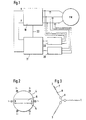
- the motor PM has three windings 1, 2 and 3 in the stator 4, each one Phase are assigned.
- the windings 1, 2, 3 are conventional in FIG. 2 shown, with a plus or minus sign next to the reference numbers, which, for example, that on windings 1 to 3 at a certain point in time applied voltages.
- a rotor 5 is rotatably mounted within the stator 4.
- This rotor has at least a permanent magnet 6, the poles of which are arranged transversely to the axis of rotation are. It goes without saying that instead of the individual magnet shown symbolically in FIG. 2 6 several star-shaped magnets can be arranged.
- the windings 1, 2, 3 can also each have a Number of winding parts arranged in a star shape in the rotor, such as this is known per se.
- FIG. 3 An equivalent circuit diagram for such a motor PM is shown in FIG. 3, with a Resistor, 8 with an inductor and 9 with a generator, which are connected in a star-shaped manner in this order. While Resistor 7 and inductance 8 the passive part of a motor phase winding 1, 2 or 3, the generator 9 forms the active part of the same.
- This Generator symbol shows that every phase winding of the motor at the same time forms a generator in which a voltage is induced which is a counter electromotive Force (BEMF - Back Electromotive Force) forms during the electromotive force (EMF - Electromotive Force) through the passive part of the Motors is generated.
- BEMF - Back Electromotive Force counter electromotive Force
- EMF electromotive Force
- Such a motor is usually controlled by a voltage frequency converter 10 - hereinafter called converter.
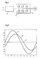
- converter 10 usually exist - provided they are operated with alternating or three-phase current - from a rectifier, an intermediate circuit and an inverter, to which a control and regulating circuit is assigned. 4 is only the inverter, so the power section 11 of the converter and the this acting control and regulating circuit 12 with the inputs V and F, where V stands for voltage and F for frequency, which is to symbolize that in The voltage or frequency depends on the signal size present there is controlled at the output of the power unit 11.
- the power section 11 exists usually from six electronic switches 13, for example thyristors, each paired with a motor phase, with the top three Switch for the generation of the voltage signal with positive sign and the lower three to generate the voltage signal with a negative sign serve.
- a converter 10 which is also known per se, can practically any waveforms for controlling the motor PM are generated.
- the motor PM is operated with sinus commutation, i. H. that the control and regulating circuit 12 according to the inputs V and F applied signals for each phase winding separately a sinusoidal Voltage curve generated, the voltage curves related to a full wave are offset from each other by 120 °. 5 shows the voltage curve as an example 14 for one of the phase windings 1, 2 or 3 shown. Will this be voltage 14 changing over time to one of the phase windings 1, 2 or 3 of the Motor applied, as is done in operation by the converter 10, so it turns out In the corresponding phase winding, a current curve that is out of phase with it 15 a.
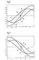
- FIG. 6 shows a part of the curve 15 that represents the current flow over time shown, namely the part where the current of its negative maximum rises to zero and then continues to rise to its positive maximum.
- 6 shows a voltage curve 16, which is the current curve 15 lags, as well as a voltage profile 17 that leads the current profile 15.
- the voltage profiles 16 and 17 are to be understood as examples and show two Constellations in which the rotor position is not the same as that generated in the stator Field rotation matches.
- the voltage curve 16 or 17 is the one that is within a motor phase winding by self-induction, namely in the phase winding, whose current profile is marked with 15, that is from Inverter 11 is powered.
- the voltage curves caused by self-induction according to curves 16 or 17 can be connected to the mains supply without complex electronic Aids cannot be measured.
- d. H. with help of a Tension meter can be measured if the corresponding one Phase winding at least during the measurement process from the supply network is disconnected or as long as the supply voltage is zero.
- This separation can with appropriate control of the converter 10 in a simple manner in that the two switches 13 of this phase are switched so that the corresponding phase winding is disconnected from the network.
- a Measuring device 20 which measures the zero crossing of the current profile 15 of each phase of the motor PM, in order to then send a corresponding signal to give a microprocessor 21 which, on the one hand, the control inputs F and V of the Converter 10 and on the other hand via a signal line 22 directly to the control and Control circuit 12 of the converter 10 for switching the switch 13 is connected.
- the measuring device 20 does not convey the complete current profile 15 in one each phase winding 1, 2 or 3, but only the zero crossing of the Current course, in each of the phase windings 1, 2, 3 and above whether the current flow increases or decreases from minus to plus is.
- the latter information can alternatively also come from the control and regulating circuit 12 of the converter 10 are derived.
- the measuring device 20 in a phase winding 1, 2 or 3 is via the microprocessor 21 and Signal line 22 by means of the associated switch pair 13 the corresponding Phase winding separated from the supply network.
- another measuring device 23 in the form of a voltmeter activated which then lies in the same phase winding Tension measures, at least according to the sign. In the diagram 6 this would be, for example, a negative voltage 24 with a voltage curve according to curve 16 or a positive voltage 25 with a voltage curve according to curve 17.
- the measuring device 23 also includes a comparator that determines whether there is a positive voltage 25, a negative Voltage 24 or zero voltage at the time of measurement results.
- the induction voltage 24 determined at the zero crossing of the current is negative, which means lagging self-induction with increasing motor current.
- the Microprocessor 21 therefore controls the converter with a lower frequency and / or a higher voltage so as to shift this phase between Correct current flow and self-induction. Otherwise, immediately after measurement, the voltage by closing the associated switch pair 13 again applied to the corresponding phase winding. Because the voltage application the individual phase winding is offset by 120 °, the also fall Zero crossings of the phase winding currents never together, so it can be for everyone Phase currents the same measuring device 20 (zero crossing detector) and the same measuring device 23 are used, even if in every zero crossing a measurement is made of each phase winding current. Results in the measurement a positive voltage 25, as shown by curve 17, so With increasing current, this means that self-induction leads and the Increasing the drive frequency for the motor or lowering the voltage is what is regulated by the microprocessor 21.
- the regulation can be refined to that effect be that by the measuring device 23 not only the sign of the phase shift, but also its size, d. H. the tension of self - induction in Zero crossing of the associated phase winding current determined and processed is, so that with large deviations a larger countermeasure than can be done with smaller ones.
- FIG. 9 shows the voltage and current curve before, during and after switching off the supply voltage applied to a motor phase winding presented for the purpose of measuring self-induction.
- the one in FIG. 9 with 26 Marked point denotes the point in time at which the winding current Is zero. At this moment, no current is flowing regardless of the current Supply voltage can be switched load-free. So the tension becomes Time 26 switched off, as shown in the lower diagram in FIG. 9 by the arrows below on line 26 is shown. Even if the external Supply voltage through the corresponding switching process from the motor phase winding is taken, depending on the situation rotating field of rotation of the stator and the rotor rotating therein either one positive voltage 27 or a negative voltage 28 which is the BEMF signal represents, d. H. which is caused by self-induction.
Landscapes
- Engineering & Computer Science (AREA)
- Power Engineering (AREA)
- Control Of Ac Motors In General (AREA)
Applications Claiming Priority (2)
| Application Number | Priority Date | Filing Date | Title |
|---|---|---|---|
| DE19860446A DE19860446A1 (de) | 1998-12-28 | 1998-12-28 | Verfahren zur Regelung eines spannungs-/frequenzumrichtergesteuerten Mehrphasen-Permanentmagnetmotors |
| DE19860446 | 1998-12-28 |
Publications (4)
| Publication Number | Publication Date |
|---|---|
| EP1017159A2 true EP1017159A2 (fr) | 2000-07-05 |
| EP1017159A3 EP1017159A3 (fr) | 2001-02-28 |
| EP1017159B1 EP1017159B1 (fr) | 2005-07-27 |
| EP1017159B2 EP1017159B2 (fr) | 2010-07-28 |
Family
ID=7892936
Family Applications (1)
| Application Number | Title | Priority Date | Filing Date |
|---|---|---|---|
| EP99125274A Expired - Lifetime EP1017159B2 (fr) | 1998-12-28 | 1999-12-18 | Méthode de régulation d'un moteur électrique monophasé ou polyphasé commandé par un convertisseur tension/fréquence |
Country Status (3)
| Country | Link |
|---|---|
| US (1) | US6208112B1 (fr) |
| EP (1) | EP1017159B2 (fr) |
| DE (2) | DE19860446A1 (fr) |
Cited By (2)
| Publication number | Priority date | Publication date | Assignee | Title |
|---|---|---|---|---|
| DE10225610A1 (de) * | 2002-06-07 | 2004-01-08 | Trinamic Microchips Gmbh | Verfahren und Schaltungsanordnung zum Betreiben von Schrittmotoren |
| EP1104087A3 (fr) * | 1999-11-23 | 2004-04-21 | Texas Instruments Incorporated | Méthode et dispositif pour contrôler l'alimentation d'un moteur DC pour lecteur de disque afin de réduire le bruit |
Families Citing this family (35)
| Publication number | Priority date | Publication date | Assignee | Title |
|---|---|---|---|---|
| DE10063054A1 (de) * | 2000-12-18 | 2002-06-20 | Wilo Gmbh | Sensorloses Ansteuerverfahren |
| US8337166B2 (en) | 2001-11-26 | 2012-12-25 | Shurflo, Llc | Pump and pump control circuit apparatus and method |
| DE10216597B4 (de) * | 2002-04-15 | 2006-09-21 | Siemens Ag | Lenkung mit elektrischer Lenkhilfe |
| US6834407B2 (en) * | 2002-12-17 | 2004-12-28 | General Electric Company | Method and apparatus for electronically commutated motor washer agitation controller |
| US7121269B2 (en) * | 2003-04-16 | 2006-10-17 | Michael North | Hot-start solenoid valve |
| DE10346711A1 (de) * | 2003-10-08 | 2005-05-25 | Minebea Co., Ltd. | Verfahren zur Kommutierung eines bürstenlosen Gleichstrommotors |
| US8540493B2 (en) | 2003-12-08 | 2013-09-24 | Sta-Rite Industries, Llc | Pump control system and method |
| JP4363169B2 (ja) * | 2003-12-11 | 2009-11-11 | パナソニック株式会社 | 食器洗い機のモータ駆動装置 |
| DE102004062580B4 (de) * | 2004-08-23 | 2008-07-24 | Diehl Ako Stiftung & Co. Kg | Verfahren und Vorrichtung zur Regelung eines mehrphasigen, elektronisch kommutierten Motors |
| US7845913B2 (en) | 2004-08-26 | 2010-12-07 | Pentair Water Pool And Spa, Inc. | Flow control |
| US8480373B2 (en) | 2004-08-26 | 2013-07-09 | Pentair Water Pool And Spa, Inc. | Filter loading |
| US8469675B2 (en) | 2004-08-26 | 2013-06-25 | Pentair Water Pool And Spa, Inc. | Priming protection |
| US7874808B2 (en) | 2004-08-26 | 2011-01-25 | Pentair Water Pool And Spa, Inc. | Variable speed pumping system and method |
| US8602745B2 (en) | 2004-08-26 | 2013-12-10 | Pentair Water Pool And Spa, Inc. | Anti-entrapment and anti-dead head function |
| US7854597B2 (en) * | 2004-08-26 | 2010-12-21 | Pentair Water Pool And Spa, Inc. | Pumping system with two way communication |
| US7686589B2 (en) | 2004-08-26 | 2010-03-30 | Pentair Water Pool And Spa, Inc. | Pumping system with power optimization |
| US8019479B2 (en) * | 2004-08-26 | 2011-09-13 | Pentair Water Pool And Spa, Inc. | Control algorithm of variable speed pumping system |
| EP1816739B1 (fr) * | 2006-02-04 | 2008-04-09 | Diehl AKO Stiftung & Co. KG | Procédé et dispositif de contrôle d'un moteur polyphasée et à commutation électronique |
| CN101110648B (zh) * | 2006-07-18 | 2010-11-24 | 华为技术有限公司 | 检测pon中故障onu的方法 |
| JP2009065806A (ja) * | 2007-09-10 | 2009-03-26 | Panasonic Corp | ステッピングモータ駆動装置及びステッピングモータ駆動方法 |
| WO2009083891A2 (fr) * | 2007-12-28 | 2009-07-09 | Koninklijke Philips Electronics N.V. | Amplificateur à modulation d'impulsions en durée pour moteur planaire inversé |
| ITBO20080047A1 (it) * | 2008-01-25 | 2009-07-26 | Spal Automotive Srl | Azionamento elettrico e metodo di pilotaggio dello stesso. |
| AU2009302593B2 (en) | 2008-10-06 | 2015-05-28 | Danfoss Low Power Drives | Method of operating a safety vacuum release system |
| US8564233B2 (en) | 2009-06-09 | 2013-10-22 | Sta-Rite Industries, Llc | Safety system and method for pump and motor |
| US9556874B2 (en) * | 2009-06-09 | 2017-01-31 | Pentair Flow Technologies, Llc | Method of controlling a pump and motor |
| US8436559B2 (en) | 2009-06-09 | 2013-05-07 | Sta-Rite Industries, Llc | System and method for motor drive control pad and drive terminals |
| US9243413B2 (en) | 2010-12-08 | 2016-01-26 | Pentair Water Pool And Spa, Inc. | Discharge vacuum relief valve for safety vacuum release system |
| BR112014010665A2 (pt) | 2011-11-01 | 2017-12-05 | Pentair Water Pool & Spa Inc | sistema e processo de bloqueio de vazão |
| DE102011056865B3 (de) * | 2011-12-22 | 2013-01-03 | Az Pokorny S.R.O. | Einrichtung zur Steuerung einer Heizungsumwälzpumpe und Steuerungsverfahren |
| US9885360B2 (en) | 2012-10-25 | 2018-02-06 | Pentair Flow Technologies, Llc | Battery backup sump pump systems and methods |
| DE102014107949A1 (de) * | 2014-06-05 | 2015-12-17 | Hella Kgaa Hueck & Co. | Verfahren und Vorrichtung zur Erkennung eines Nulldurchgangs eines Stroms durch einen Strang eines bürstenlosen Gleichstrom- motors |
| DE102016211406A1 (de) | 2016-06-24 | 2017-12-28 | Robert Bosch Gmbh | Verfahren zur Regelung einer Synchronmaschine und Regelvorrichtung für eine Synchronmaschine |
| DE102017117109A1 (de) * | 2017-07-28 | 2019-01-31 | Miele & Cie. Kg | Ansteuerung eines bürstenlosen Gleichstrommotors |
| BE1029065B1 (de) * | 2021-01-28 | 2022-08-29 | Miele & Cie | Verfahren zum Ansteuern eines mindestens zweiphasigen bürstenlosen Motors |
| US11916497B2 (en) * | 2021-11-17 | 2024-02-27 | Horstmann Systems Corporation | Variable-speed drive for single-phase asynchronous motors |
Citations (1)
| Publication number | Priority date | Publication date | Assignee | Title |
|---|---|---|---|---|
| EP0801463A1 (fr) | 1996-04-12 | 1997-10-15 | STMicroelectronics S.A. | Régulation d'un moteur sans balai |
Family Cites Families (8)
| Publication number | Priority date | Publication date | Assignee | Title |
|---|---|---|---|---|
| JPH0732634B2 (ja) † | 1989-03-15 | 1995-04-10 | インターナショナル・ビジネス・マシーンズ・コーポレーション | 無刷子直流モータの始動方法 |
| EP0571076B1 (fr) * | 1992-04-10 | 1996-01-17 | Matsushita Electric Industrial Co., Ltd. | Moteur à courant continu sans balai |
| US5448149A (en) † | 1994-06-20 | 1995-09-05 | Texas A&M University | Indirect rotor position sensor for a sinusoidal synchronous reluctance machine |
| JPH08235015A (ja) | 1995-02-27 | 1996-09-13 | Mitsubishi Electric Corp | プロセッサ装置並びにプロセッサ故障診断方法 |
| DE69613810T2 (de) † | 1996-04-04 | 2001-10-25 | Stmicroelectronics S.R.L., Agrate Brianza | Synchronsteuerung der Phasenwicklungen eines Gleichstrommotors mit vorbestimmten digitalisierten permanent gespeicherten Ansteuerungsprofilen, deren Auslesung mit der Rotorstellung synchronisiert ist zur Optimierung des Drehmomentsverlaufs |
| JPH1080180A (ja) * | 1996-09-05 | 1998-03-24 | Fujii Seimitsu Kaitenki Seisakusho:Kk | 同期電動機の制御方法及び装置 |
| US5929622A (en) * | 1998-07-01 | 1999-07-27 | Quantum Corporation | Balanced current mirror |
| DE19846831B4 (de) † | 1998-10-10 | 2008-05-29 | Diehl Ako Stiftung & Co. Kg | Verfahren und Vorrichtung zur Ermittlung der Rotorstellung von Synchronmotoren |
-
1998
- 1998-12-28 DE DE19860446A patent/DE19860446A1/de not_active Ceased
-
1999
- 1999-12-18 DE DE59912325T patent/DE59912325D1/de not_active Expired - Lifetime
- 1999-12-18 EP EP99125274A patent/EP1017159B2/fr not_active Expired - Lifetime
- 1999-12-24 US US09/471,671 patent/US6208112B1/en not_active Expired - Lifetime
Patent Citations (1)
| Publication number | Priority date | Publication date | Assignee | Title |
|---|---|---|---|---|
| EP0801463A1 (fr) | 1996-04-12 | 1997-10-15 | STMicroelectronics S.A. | Régulation d'un moteur sans balai |
Cited By (3)
| Publication number | Priority date | Publication date | Assignee | Title |
|---|---|---|---|---|
| EP1104087A3 (fr) * | 1999-11-23 | 2004-04-21 | Texas Instruments Incorporated | Méthode et dispositif pour contrôler l'alimentation d'un moteur DC pour lecteur de disque afin de réduire le bruit |
| DE10225610A1 (de) * | 2002-06-07 | 2004-01-08 | Trinamic Microchips Gmbh | Verfahren und Schaltungsanordnung zum Betreiben von Schrittmotoren |
| DE10225610B4 (de) * | 2002-06-07 | 2006-12-28 | Trinamic Motion Control Gmbh & Co. Kg | Verfahren und Schaltungsanordnung zum Betreiben eines Schrittmotors |
Also Published As
| Publication number | Publication date |
|---|---|
| US6208112B1 (en) | 2001-03-27 |
| DE19860446A1 (de) | 2000-06-29 |
| EP1017159B2 (fr) | 2010-07-28 |
| DE59912325D1 (de) | 2005-09-01 |
| EP1017159B1 (fr) | 2005-07-27 |
| EP1017159A3 (fr) | 2001-02-28 |
Similar Documents
| Publication | Publication Date | Title |
|---|---|---|
| EP1017159B2 (fr) | Méthode de régulation d'un moteur électrique monophasé ou polyphasé commandé par un convertisseur tension/fréquence | |
| DE3686722T2 (de) | Buerstenfreier gleichstrommotor. | |
| DE19846831B4 (de) | Verfahren und Vorrichtung zur Ermittlung der Rotorstellung von Synchronmotoren | |
| EP1816739B1 (fr) | Procédé et dispositif de contrôle d'un moteur polyphasée et à commutation électronique | |
| EP0179356B1 (fr) | Procédé et dispositif de régulation d'une machine à champ tournant | |
| DE10054594B4 (de) | Vorrichtung zum Erfassen der Rotorposition in einem bürstenlosen Gleichstrommotor | |
| DE69822896T2 (de) | Verfahren und gerät zur steuerung eines bürstenlosen elektrischen motors | |
| DE3934139C2 (de) | Elektronische Steuerschaltung für einen bürstenlosen Gleichstrommotor | |
| EP1499008B1 (fr) | Méthode et système de commande pour la commutation électronique d'un moteur DC sans balais | |
| DE3236692A1 (de) | Wechselrichter-system | |
| EP1695437B1 (fr) | Commande d'un moteur a courant continu sans balais | |
| EP1728316B1 (fr) | Procede de demarrage d'un moteur a courant continu depourvu de detecteur et a commutation electronique | |
| EP1514342B1 (fr) | Procede et ensemble de circuits pour faire fonctionner des moteurs pas a pas | |
| DE69724414T2 (de) | Verfahren zum bearbeiten eines elektronisch kommutierten, variablen reluktanzmotors und stromversorgungs-schalkreis dafür | |
| DE10332228B4 (de) | Steuerungsverfahren für einen bürstenlosen Elektromotor, insbesonde Lüftermotor | |
| DE19946050A1 (de) | Verfahren zur Drehzahlregelung für geschaltete Reluktanzmotoren (GRM) | |
| DE102019110045A1 (de) | Verfahren zum Betrieb eines Antriebssystems mit einem Einphasen-Synchronmotor | |
| DE69732701T2 (de) | Verfahren und vorrichtung zur steuerung von elektrischen motor-generatoren | |
| EP1443635B1 (fr) | Procédé de contrôle d'un angle d'allumage et moteur électrique alimenté en courant monophasé | |
| DE102004062580B4 (de) | Verfahren und Vorrichtung zur Regelung eines mehrphasigen, elektronisch kommutierten Motors | |
| DE102017211196A1 (de) | Verfahren zum Betreiben einer elektronisch kommutierten Synchronmaschine und Ansteuerschaltung | |
| DE102012012762B4 (de) | Einrichtung zur Bestimmung von Positionen eines Rotors in elektrischen Maschinen | |
| DE3609678C2 (de) | Antriebsanordnung mit kollektorlosem Gleichstrommotor | |
| WO1997048177A1 (fr) | Systeme comportant un moteur a commutation electronique | |
| DE3525421C2 (fr) |
Legal Events
| Date | Code | Title | Description |
|---|---|---|---|
| PUAI | Public reference made under article 153(3) epc to a published international application that has entered the european phase |
Free format text: ORIGINAL CODE: 0009012 |
|
| AK | Designated contracting states |
Kind code of ref document: A2 Designated state(s): DE FR GB IT |
|
| AX | Request for extension of the european patent |
Free format text: AL;LT;LV;MK;RO;SI |
|
| PUAL | Search report despatched |
Free format text: ORIGINAL CODE: 0009013 |
|
| AK | Designated contracting states |
Kind code of ref document: A3 Designated state(s): AT BE CH CY DE DK ES FI FR GB GR IE IT LI LU MC NL PT SE |
|
| AX | Request for extension of the european patent |
Free format text: AL;LT;LV;MK;RO;SI |
|
| RIC1 | Information provided on ipc code assigned before grant |
Free format text: 7H 02P 6/08 A, 7H 02P 6/00 B, 7H 02P 6/14 B, 7H 02P 6/18 B |
|
| RIC1 | Information provided on ipc code assigned before grant |
Free format text: 7H 02P 6/08 A |
|
| 17P | Request for examination filed |
Effective date: 20010528 |
|
| AKX | Designation fees paid |
Free format text: DE FR GB IT |
|
| 17Q | First examination report despatched |
Effective date: 20020718 |
|
| GRAP | Despatch of communication of intention to grant a patent |
Free format text: ORIGINAL CODE: EPIDOSNIGR1 |
|
| GRAS | Grant fee paid |
Free format text: ORIGINAL CODE: EPIDOSNIGR3 |
|
| GRAA | (expected) grant |
Free format text: ORIGINAL CODE: 0009210 |
|
| AK | Designated contracting states |
Kind code of ref document: B1 Designated state(s): DE FR GB IT |
|
| REG | Reference to a national code |
Ref country code: GB Ref legal event code: FG4D Free format text: NOT ENGLISH |
|
| REF | Corresponds to: |
Ref document number: 59912325 Country of ref document: DE Date of ref document: 20050901 Kind code of ref document: P |
|
| GBT | Gb: translation of ep patent filed (gb section 77(6)(a)/1977) |
Effective date: 20051005 |
|
| ET | Fr: translation filed | ||
| PLBI | Opposition filed |
Free format text: ORIGINAL CODE: 0009260 |
|
| 26 | Opposition filed |
Opponent name: DIEHL AKO STIFTUNG & CO. KG Effective date: 20060427 |
|
| PLAX | Notice of opposition and request to file observation + time limit sent |
Free format text: ORIGINAL CODE: EPIDOSNOBS2 |
|
| PLAF | Information modified related to communication of a notice of opposition and request to file observations + time limit |
Free format text: ORIGINAL CODE: EPIDOSCOBS2 |
|
| PLBB | Reply of patent proprietor to notice(s) of opposition received |
Free format text: ORIGINAL CODE: EPIDOSNOBS3 |
|
| PLBP | Opposition withdrawn |
Free format text: ORIGINAL CODE: 0009264 |
|
| PUAH | Patent maintained in amended form |
Free format text: ORIGINAL CODE: 0009272 |
|
| STAA | Information on the status of an ep patent application or granted ep patent |
Free format text: STATUS: PATENT MAINTAINED AS AMENDED |
|
| 27A | Patent maintained in amended form |
Effective date: 20100728 |
|
| AK | Designated contracting states |
Kind code of ref document: B2 Designated state(s): DE FR GB IT |
|
| REG | Reference to a national code |
Ref country code: FR Ref legal event code: PLFP Year of fee payment: 17 |
|
| PGFP | Annual fee paid to national office [announced via postgrant information from national office to epo] |
Ref country code: IT Payment date: 20151111 Year of fee payment: 17 Ref country code: GB Payment date: 20151207 Year of fee payment: 17 |
|
| PGFP | Annual fee paid to national office [announced via postgrant information from national office to epo] |
Ref country code: FR Payment date: 20151023 Year of fee payment: 17 |
|
| PGFP | Annual fee paid to national office [announced via postgrant information from national office to epo] |
Ref country code: DE Payment date: 20160105 Year of fee payment: 17 |
|
| REG | Reference to a national code |
Ref country code: DE Ref legal event code: R119 Ref document number: 59912325 Country of ref document: DE |
|
| GBPC | Gb: european patent ceased through non-payment of renewal fee |
Effective date: 20161218 |
|
| REG | Reference to a national code |
Ref country code: FR Ref legal event code: ST Effective date: 20170831 |
|
| PG25 | Lapsed in a contracting state [announced via postgrant information from national office to epo] |
Ref country code: IT Free format text: LAPSE BECAUSE OF NON-PAYMENT OF DUE FEES Effective date: 20161218 Ref country code: FR Free format text: LAPSE BECAUSE OF NON-PAYMENT OF DUE FEES Effective date: 20170102 |
|
| PG25 | Lapsed in a contracting state [announced via postgrant information from national office to epo] |
Ref country code: GB Free format text: LAPSE BECAUSE OF NON-PAYMENT OF DUE FEES Effective date: 20161218 Ref country code: DE Free format text: LAPSE BECAUSE OF NON-PAYMENT OF DUE FEES Effective date: 20170701 |