EP1017189A1 - Satellit mit rundstrahlender Antenne - Google Patents
Satellit mit rundstrahlender Antenne Download PDFInfo
- Publication number
- EP1017189A1 EP1017189A1 EP99403261A EP99403261A EP1017189A1 EP 1017189 A1 EP1017189 A1 EP 1017189A1 EP 99403261 A EP99403261 A EP 99403261A EP 99403261 A EP99403261 A EP 99403261A EP 1017189 A1 EP1017189 A1 EP 1017189A1
- Authority
- EP
- European Patent Office
- Prior art keywords
- antennas
- signals
- satellite
- spread spectrum
- transmission
- Prior art date
- Legal status (The legal status is an assumption and is not a legal conclusion. Google has not performed a legal analysis and makes no representation as to the accuracy of the status listed.)
- Granted
Links
- 238000001228 spectrum Methods 0.000 claims abstract description 48
- 230000005540 biological transmission Effects 0.000 claims abstract description 34
- 238000010586 diagram Methods 0.000 claims abstract description 27
- 238000000034 method Methods 0.000 claims description 16
- 230000008054 signal transmission Effects 0.000 claims description 4
- 230000003111 delayed effect Effects 0.000 claims description 2
- 239000000243 solution Substances 0.000 description 11
- 230000010287 polarization Effects 0.000 description 9
- 101100172132 Mus musculus Eif3a gene Proteins 0.000 description 2
- PCHJSUWPFVWCPO-UHFFFAOYSA-N gold Chemical compound [Au] PCHJSUWPFVWCPO-UHFFFAOYSA-N 0.000 description 2
- 239000010931 gold Substances 0.000 description 2
- 229910052737 gold Inorganic materials 0.000 description 2
- 238000002347 injection Methods 0.000 description 2
- 239000007924 injection Substances 0.000 description 2
- 238000003780 insertion Methods 0.000 description 2
- 230000037431 insertion Effects 0.000 description 2
- 238000005259 measurement Methods 0.000 description 2
- 230000010363 phase shift Effects 0.000 description 2
- 238000005311 autocorrelation function Methods 0.000 description 1
- 238000004364 calculation method Methods 0.000 description 1
- 230000015556 catabolic process Effects 0.000 description 1
- 230000001427 coherent effect Effects 0.000 description 1
- 238000005314 correlation function Methods 0.000 description 1
- 238000005388 cross polarization Methods 0.000 description 1
- 230000009849 deactivation Effects 0.000 description 1
- 230000007423 decrease Effects 0.000 description 1
- 238000001514 detection method Methods 0.000 description 1
- 238000009413 insulation Methods 0.000 description 1
- 230000010354 integration Effects 0.000 description 1
- 238000002955 isolation Methods 0.000 description 1
- 238000012545 processing Methods 0.000 description 1
- 230000006798 recombination Effects 0.000 description 1
- 238000005215 recombination Methods 0.000 description 1
- 230000001360 synchronised effect Effects 0.000 description 1
- 238000011144 upstream manufacturing Methods 0.000 description 1
Images
Classifications
-
- H—ELECTRICITY
- H04—ELECTRIC COMMUNICATION TECHNIQUE
- H04B—TRANSMISSION
- H04B7/00—Radio transmission systems, i.e. using radiation field
- H04B7/14—Relay systems
- H04B7/15—Active relay systems
- H04B7/204—Multiple access
- H04B7/216—Code division or spread-spectrum multiple access [CDMA, SSMA]
Definitions
- the present invention relates to a signal transmission method to a satellite with at least two antennas whose diagrams are at least partially overlap; it also relates to a transmission method signals from or to such a satellite. It also concerns a satellite with at least two antennas whose diagrams overlap the less partially.
- TTC link is kept; this should be ensured as wide a satellite coverage as possible, especially for critical phases of rescue, stationing and deorbiting.
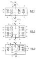
- Figure 1 shows a schematic representation of a known satellite; the satellite 1 includes an omnidirectional antenna 3 called an earth antenna, and a omnidirectional antenna 5 located on the other side of the satellite, called anti-earth antenna.
- the two antennas are connected to a coupler 7, which makes it possible to add the signals from the antennas, and that transmits the sum of the signals to either of two Rx 9 and 11 receptors; two hot redundant receivers are provided so that allow the satellite to continue operating if one of the receivers stops function.
- the summation of the signals of the two antennas makes it possible to obtain a coverage, on the earth and anti-earth faces of the satellite.
- This type of device has the following disadvantages.
- the signals received by the satellite on the earth and anti-earth antennas are added; a phenomenon of multiple paths then occurs, which disturbs the signal reception.
- a symmetrical problem is encountered in telemetry, i. e. for transmitting signals from the satellite: there are then two Tx 10 transmitters and 12 in cold redundancy, with a coupler 8; signals from the active transmitter are transmitted to the earth and anti-earth antennas.
- the antennas can be separated in transmission and in reception.
- ESA programs or CNES propose to use crossed circular polarizations for antennas earth and anti-earth.
- a polarization for example a right circular polarization, is dedicated to the earth antenna, and the cross polarization, for example circular left is dedicated to the anti-earth antenna.
- the operation of the satellite is similar to that described with reference to Figure 1 outside the overlap area of antenna diagrams, except that ground stations must transmit a wave whose polarization is a function of the position of the satellite.
- polarization isolation limits the impact of multipath on recombination signals from the two antennas. It is possible to obtain coverage satisfactory in the antenna overlap area, for insulation of polarization of the order of 10 dB.
- the solution is symmetric in telemetry.
- This solution has the drawback of generating a small loss in the link budget; above all, it requires a circular incident wave, which which is not the case for example for certain stations in Ku band, for example the TELESAT network in linear polarization; moreover, it is difficult to know the position of the satellite to choose the appropriate polarization, especially in emergency modes.
- Figure 2 shows another known satellite.
- the satellite in Figure 2 is identical to that of FIG. 1, except that it does not include a coupler 7 and two receivers 9 and 11 receiving the signals from the two antennas, but for the antenna earth 3 a coupler 19 and two receivers 21 and 23 in hot redundancy, and for the anti-earth antenna a coupler 25 and two redundant receivers 27 and 29 hot.
- receivers 21 and 23 are used in hot redundancy, and 27 and 29 on the other hand, so that the problem of summation, and therefore of multipath, between the signals received on the earth and anti-earth antennas do not arise. It suits nevertheless, then select the signal used, which may be that coming from the earth antenna like the one coming from the anti-earth antenna.
- two transmitters 31 and 33 are used for the earth antenna. a first frequency, with a coupler 35, and for the anti-earth antenna two transmitters 37 and 39 at a second frequency, with a coupler 41. On each channel, the two transmitters are in cold redundancy. Emission at frequencies different limits the problem of multiple paths in the overlap area of earth and anti-earth antennas.
- This solution has the drawback of doubling the number of receivers; moreover, it makes the selection logic between the earth and anti-earth. In telemetry, the number of transmitters is also doubled; furthermore it is still necessary to know the position of the satellite to choose the frequency adequate.
- US-A-3,761,813 describes a satellite transmission system geostationary to planes.
- the problem of multiple paths due to reflections on the ground of signals transmitted by the satellite is to use a time multiplexing of the signals intended for the different planes; the period of the multiplex is chosen so that the reflected signals on the surface of the earth don't reach an airplane at the same time as signals intended for him.
- US-A-5,450,448 describes a satellite positioning system, and proposes a solution to the problem of multiple paths. This document proposes a processing based on calculating the differences of signals shifted in time, for reduce interference due to multipath. This document mentions other Prior art solutions to reduce interference due to multipath.
- the information in bit spectrum systems is called "information" binary transmitted on a channel, and "chip” or in English “chip” information binary associated with the pseudo-random sequence.
- PN codes codes pseudorandom most often called PN codes (acronym of English Pseudonoise). PN codes are chosen based on criteria related to their functions autocorrelation or intercorrelation, so that a receiver only decodes the signal intended for it, with a possible interference signal depending on the number of users and code properties.
- the invention proposes a solution to the problem of antenna coverage of satellites; it offers a solution to obtain antenna coverage complete of satellites, without involving duplication of transmitters or receivers.
- the modulation step preferably comprises modulation signals intended for said antennas by spreading sequences offset by at least minus a snippet.
- the transmission step comprises the application of a delay in signals intended for at least one of the antennas.
- the invention also provides a satellite having at least two antennas whose diagrams overlap at least partially, and means for reception of the sum of the signals from the different antennas, characterized in that the reception means comprise means for demodulating a spread spectrum signal, and in that the difference between the transmission times signal transmitted to the receiving means by two antennas is greater in absolute value than a chip of the spread spectrum modulation.
- the reception means comprise a coupler for signals from the antennas and at least two receivers connected to the coupler.
- the satellite comprises delay elements between at least an antenna and the reception means.
- the delay elements advantageously include a chosen element among a coaxial link, a delay line, a surface wave filter.
- the invention also provides a satellite having at least two antennas whose diagrams overlap at least partially, and means transmitting signals to the different antennas, characterized in that the means emission comprise means for modulating the signal to be transmitted by spectrum spread, and in that the difference between the transmission times respective of a signal transmitted by the transmission means by two antennas is greater in absolute value than a chip of the spread spectrum modulation.
- the invention finally proposes a satellite presenting at least two of which the diagrams overlap at least partially, and means for transmitting signals to the different antennas, characterized in that the transmission means include means for modulating the signal to be transmitted by spreading spectrum, the signals intended for the various antennas being modulated by spreading spectrum with different sequences.
- the transmission means comprise at least two cold redundant transmitters and a coupler to send signals from from transmitters to antennas.
- the satellite includes delay elements between the transmission means and at least one antenna.
- These delay elements may include an element chosen from a coaxial link, a delay line, a surface wave filter.
- the invention proposes, to provide antenna coverage in the areas of overlapping of antenna patterns, using spread modulation spectrum, and arrange or wire the antennas so the difference between them signal transmission time via two antennas is greater than a snippet of the spread spectrum modulation. It applies both to reception and to emission, and makes it possible to avoid or at least limit the problems associated with multipaths.
- the invention proposes, to limit or avoid problems in the area of overlapping the antennas, use different spreading sequences for different antennas.
- reception it is ensured that the reception means, if they hang on signal transmitted by one antenna, ignore signals transmitted by another antenna, insofar as these signals are offset by more than one chip, or are spread out by another sequence.
- Figure 3 shows a satellite according to the invention.
- the satellite of FIG. 3 comprises an omnidirectional earth antenna 3, and an omnidirectional anti-earth antenna 5 arranged back to back on either side from the satellite.
- the two antennas are connected to reception means 45.
- These reception means may include a coupler 47, which makes it possible to add the signals of the antennas, and which transmits the signals added to one or the other of two receivers 49 and 51 in cold redundancy.
- Receivers have means for demodulating a spread spectrum signal by direct sequence.
- the antennas and the means for receiving so as to ensure that the difference between the transmission times of the received signals from the earth station via one antenna and the other antenna is greater than one bit of spread spectrum modulation.
- This can be done in various ways manners.
- we can take into account the length of the link between the antennas and receivers (respectively transmitters), which are arranged on the side on either side of the satellite; this length alone can induce a difference between earth and anti-earth paths; this difference may be greater than a single bit, and to it only ensure a sufficient difference between the transmission times.
- delay elements between one or the other of the antennas and the reception means may include a coaxial link length additional 53, or active or passive delay elements, such as delay lines or surface wave filters. Use of the latter can then make frequency changes necessary before summing the signals from antennas. If necessary, an amplifier can also be provided low noise 54 upstream of the delay elements. Insertion of delay elements between at least one of the antennas and the reception means makes it possible to lengthen the difference between earth and anti-earth paths; we can then use a bit rate weaker. Thus, the insertion of a delay element of 100 ns eliminates substantially the multi-path with a spread spectrum signal greater than 10 Mbribe / s.
- the data On transmission by the ground station, the data is multiplied by a PN code; upon reception, multiplication by a synchronous PN code makes it possible to restore the data.
- PN code On transmission by the ground station, the data is multiplied by a PN code; upon reception, multiplication by a synchronous PN code makes it possible to restore the data.
- the signal received by the satellite is a signal modulated by D (t) .PN (t);
- D (t) is the sequence of data to be transmitted, which are worth ⁇ 1 for example, and
- PN (t) is the sequence of code, which also takes values ⁇ 1.
- the signal is proportional to: D (t) .PN (t) .cos ( ⁇ 0 .t + ⁇ 0 ), with ⁇ 0 the carrier pulse.
- the invention uses spread spectrum for transmission of the same signal; this avoids or limit problems related to multipaths, and overlapping of diagrams receiving antennas.
- the invention has been described in detail in the case of reception. It applies also for satellite transmission, following the same principles.
- two transmitters 55 and 56 in cold redundancy, which provide a signal to spectrum spread in direct sequence; a coupler 57 sends the signal supplied by one either of the transmitters at the two antennas.
- Delay elements are expected 58 between the coupler and one of the antennas, so the difference in ground path and anti-earth is greater than a chip regardless of the position of the terrestrial reception in the overlap area of the emission diagrams of antennas.
- the earth station receiving the signals is found in the overlap area of two satellite antennas, it receives signals that are shifted by more than one bit of the spread modulation spectrum. In this way, the earth station hangs on to one of the signals, and ignores the other.
- each of the spreading devices codes distinct; in this case, the signals transmitted by the two antennas are spread with orthogonal codes, or presenting a limited cross-correlation function.
- the receiver even if it is in the antenna overlap area, can hang on the signal from one of the antennas, without the signal from the other antenna does not pose a reception problem.
- the same signals are transmitted by the antennas, i.e. with an offset greater than a flange of the spread spectrum modulation, either on different spreading sequences.
- the invention allows the use of a single receiver receiving the sum of the signals from the antennas, without the need to select the received signal. So if the satellite gets caught on the anti-earth signal in the overlap area of the antenna diagrams, and that the power of this signal decreases because the satellite presents the antenna earth towards the transmitting station, the receiving means will lose the anti-earth signal on which they are hooked on, and then hang on to the ground signal. This is done without it being necessary to foresee it.
- the invention thus allows a reception or a broadcast in all phases, without the need to know the position of the satellite.
- the present invention is not limited to the examples and modes described and represented, but it is likely to be numerous variants accessible to those skilled in the art.
- the invention has been described with reference in the figures, in the simplest case of two earth and anti-earth antennas. She also applies in the case of multiple antennas, which present diagrams overlapping, two by two, in groups of three or more, or all together. In such a configuration, it suffices to ensure that the path difference between two signals received in the overlap area is greater than a chip.
- the invention has been described for BPSK modulation; it applies to any other type of modulation.
- the invention is particularly advantageous to implement on the link TTC or TRC of a satellite, because of the importance of maintaining this link. She can also be applied to links of another type.
- the offset between the antenna signals is at least minus a snippet.
- the offset depends on the spread used, and can be greater than this value, depending on the autocorrelation of the spreading sequence used, or the cross-correlation between the sequences used.
Landscapes
- Engineering & Computer Science (AREA)
- Computer Networks & Wireless Communication (AREA)
- Signal Processing (AREA)
- Radio Relay Systems (AREA)
- Analysing Materials By The Use Of Radiation (AREA)
- Processes Of Treating Macromolecular Substances (AREA)
- Surface Treatment Of Optical Elements (AREA)
- Waveguide Aerials (AREA)
- Support Of Aerials (AREA)
- Aerials With Secondary Devices (AREA)
Applications Claiming Priority (2)
| Application Number | Priority Date | Filing Date | Title |
|---|---|---|---|
| FR9816713 | 1998-12-31 | ||
| FR9816713A FR2788179B1 (fr) | 1998-12-31 | 1998-12-31 | Satellite a couverture omnidirectionnelle |
Publications (2)
| Publication Number | Publication Date |
|---|---|
| EP1017189A1 true EP1017189A1 (de) | 2000-07-05 |
| EP1017189B1 EP1017189B1 (de) | 2006-08-02 |
Family
ID=9534745
Family Applications (1)
| Application Number | Title | Priority Date | Filing Date |
|---|---|---|---|
| EP99403261A Expired - Lifetime EP1017189B1 (de) | 1998-12-31 | 1999-12-23 | Satellit mit rundstrahlender Antenne |
Country Status (6)
| Country | Link |
|---|---|
| US (1) | US6862269B1 (de) |
| EP (1) | EP1017189B1 (de) |
| AT (1) | ATE335320T1 (de) |
| CA (1) | CA2296204C (de) |
| DE (1) | DE69932584T2 (de) |
| FR (1) | FR2788179B1 (de) |
Families Citing this family (7)
| Publication number | Priority date | Publication date | Assignee | Title |
|---|---|---|---|---|
| DE102005027453A1 (de) * | 2005-06-14 | 2006-12-28 | Fraunhofer-Gesellschaft zur Förderung der angewandten Forschung e.V. | Terrestrische Sendestation zum Aussenden eines terrestrischen Rundfunksignals, satellitengestütztes Rundfunksystem und Empfänger für ein satellitengestütztes Rundfunksystem |
| EP2074711A2 (de) * | 2006-10-06 | 2009-07-01 | ViaSat, Inc. | Vorwärts- und rückwärtskalibration für bodengestützte strahlformung |
| US8112261B2 (en) * | 2008-03-31 | 2012-02-07 | Gm Global Technology Operations, Llc. | Methods and simulation tools for predicting GPS performance in the broad operating environment |
| US8977309B2 (en) * | 2009-09-21 | 2015-03-10 | Kathrein-Werke Kg | Antenna array, network planning system, communication network and method for relaying radio signals with independently configurable beam pattern shapes using a local knowledge |
| US9584199B2 (en) | 2009-09-21 | 2017-02-28 | Kathrein-Werke Kg | User group specific beam forming in a mobile network |
| US8391334B1 (en) | 2010-09-27 | 2013-03-05 | L-3 Communications Corp | Communications reliability in a hub-spoke communications system |
| FR3130393B1 (fr) * | 2021-12-09 | 2023-11-03 | Thales Sa | Agencement d'antennes TTC pour satellite plat |
Citations (2)
| Publication number | Priority date | Publication date | Assignee | Title |
|---|---|---|---|---|
| EP0639009A1 (de) * | 1993-08-13 | 1995-02-15 | Matra Communication | Verfahren und Anordnung zur Übertragung mittels CDMA-Funkkommunikation |
| WO1998056123A1 (en) * | 1997-06-02 | 1998-12-10 | Motorola, Inc. | System and method using polarized cdma signals |
Family Cites Families (14)
| Publication number | Priority date | Publication date | Assignee | Title |
|---|---|---|---|---|
| US6067442A (en) * | 1991-10-10 | 2000-05-23 | Globalstar L.P. | Satellite communications system having distributed user assignment and resource assignment with terrestrial gateways |
| US6157811A (en) * | 1994-01-11 | 2000-12-05 | Ericsson Inc. | Cellular/satellite communications system with improved frequency re-use |
| US5953370A (en) * | 1994-09-09 | 1999-09-14 | Omnipoint Corporation | Apparatus for receiving and correlating a spread spectrum signal |
| JP3598609B2 (ja) * | 1995-09-20 | 2004-12-08 | 双葉電子工業株式会社 | スペクトル拡散通信システムにおける受信装置 |
| US6061388A (en) * | 1996-06-07 | 2000-05-09 | General Electric Company | Spread spectrum communication system with frequency-separated message and reference signals |
| JP3105786B2 (ja) * | 1996-06-13 | 2000-11-06 | 松下電器産業株式会社 | 移動体通信受信機 |
| US6327534B1 (en) * | 1996-09-30 | 2001-12-04 | Qualcomm Incorporated | Unambiguous position determination using two low-earth orbit satellites |
| US6067019A (en) * | 1996-11-25 | 2000-05-23 | Hill-Rom, Inc. | Bed exit detection apparatus |
| JP3300252B2 (ja) * | 1997-04-02 | 2002-07-08 | 松下電器産業株式会社 | 適応送信ダイバーシチ装置及び適応送信ダイバーシチ方法 |
| US5923292A (en) * | 1997-07-11 | 1999-07-13 | Space Systems/Loral, Inc. | Dual antenna null elimination |
| KR100239177B1 (ko) * | 1997-08-30 | 2000-01-15 | 윤종용 | 씨디엠에이 이동통신시스템에서 파일럿 신호를 이용한 스마트안테나 수신장치 및 방법 |
| US6055431A (en) * | 1997-12-19 | 2000-04-25 | The Aerospace Corporation | Adaptive control of multiple beam communication transponders |
| US6272345B1 (en) * | 1998-07-31 | 2001-08-07 | Motorola, Inc. | Method and apparatus for region based hand-offs in a satellite communication system |
| US6192217B1 (en) * | 1999-07-01 | 2001-02-20 | Assuresat, Inc. | Universal replacement communications satellite |
-
1998
- 1998-12-31 FR FR9816713A patent/FR2788179B1/fr not_active Expired - Fee Related
-
1999
- 1999-12-23 US US09/471,281 patent/US6862269B1/en not_active Expired - Lifetime
- 1999-12-23 AT AT99403261T patent/ATE335320T1/de not_active IP Right Cessation
- 1999-12-23 EP EP99403261A patent/EP1017189B1/de not_active Expired - Lifetime
- 1999-12-23 CA CA2296204A patent/CA2296204C/fr not_active Expired - Lifetime
- 1999-12-23 DE DE69932584T patent/DE69932584T2/de not_active Expired - Lifetime
Patent Citations (2)
| Publication number | Priority date | Publication date | Assignee | Title |
|---|---|---|---|---|
| EP0639009A1 (de) * | 1993-08-13 | 1995-02-15 | Matra Communication | Verfahren und Anordnung zur Übertragung mittels CDMA-Funkkommunikation |
| WO1998056123A1 (en) * | 1997-06-02 | 1998-12-10 | Motorola, Inc. | System and method using polarized cdma signals |
Also Published As
| Publication number | Publication date |
|---|---|
| DE69932584D1 (de) | 2006-09-14 |
| CA2296204C (fr) | 2010-02-16 |
| ATE335320T1 (de) | 2006-08-15 |
| EP1017189B1 (de) | 2006-08-02 |
| FR2788179A1 (fr) | 2000-07-07 |
| CA2296204A1 (fr) | 2000-06-30 |
| DE69932584T2 (de) | 2007-10-25 |
| US6862269B1 (en) | 2005-03-01 |
| FR2788179B1 (fr) | 2003-06-20 |
Similar Documents
| Publication | Publication Date | Title |
|---|---|---|
| FR2768576A1 (fr) | Procede de gestion des dents et du recepteur en rateau pour assurer une communication a spectre etale | |
| EP2555016A1 (de) | Nutzlast eines Satelliten für Leistungserhöhungssysteme | |
| EP1017189B1 (de) | Satellit mit rundstrahlender Antenne | |
| EP0641096B1 (de) | Verfahren mit mehrfachem Zugang durch Einteilung in orthogonale Frequenzen, entsprechende zentrale Station, entfernte Station, System und deren Verwendung | |
| EP1360781B1 (de) | Abstands-messvorrichtung, folgung und steuerung für satelliten | |
| EP0541406A1 (de) | Verfahren und Gerät zur Übertragung zweier Informationen über eine Spreizspektrumverbindung | |
| EP0820157B1 (de) | Verfahren zur digitalen Differenzialdemodulation | |
| EP0778678B1 (de) | Differentialempfänger für Direktsequenzspreizspektrumsignale | |
| WO2001005063A1 (fr) | Procede et systeme de telecommunication par satellites defilants dans lequel les communications sont transferables d'un satellite a un autre | |
| WO2010106280A1 (fr) | Charge utile d'un ais satellite et procede correspondant | |
| EP0570273B1 (de) | Verfahren zur Entspreizung beim Empfang eines Breitbandsignals | |
| EP0994580B1 (de) | Übertragungsverfahren in einem Funkkommunikationssystem mit Vielfachzugriff | |
| EP0998065A1 (de) | Kanalmodul zur Gewinnung und Nachziehregelung in einem Radionachrichtenübertragungssstem | |
| EP1142437B1 (de) | Verfahren zur atm-telekommunikation wobei endgeräte mit einer station verbunden sind | |
| EP2720064B1 (de) | Synchronisierungssystem einer Vorrichtung zur Satellitenausrichtung | |
| EP0876720B1 (de) | Bidirektionales funksignal gebrauchende senderempfänger-endgeräte mit einer einzigen trägerfrequenz für beide richtungen | |
| EP0859472A1 (de) | Kodemultiplexvielfachzugriffssender | |
| EP0023511B1 (de) | Verfahren und vorrichtung zum feststellen und auswerten eines notsignals | |
| EP1550234A1 (de) | Verfahren zum empfangen von signalen in einem spreizspektrum-telekommunikationssystem mit terrestrischen zwischenverstärkern mit einer komplementären quelle | |
| CA2364867C (fr) | Procedes et dispositif de traitement en reception d'un signal de transmission numerique a bande etalee | |
| EP0531203B1 (de) | Verfahren und Anordnung zur Informationsübertragung und zur Lokalisierung beweglicher Objekte | |
| EP2724179B1 (de) | Optimierung eines ortungssystems mit terrestrischen sendebasisstationen | |
| FR2573594A1 (fr) | Procede de transmission par etalement de spectre dans un reseau de communications, et poste emetteur-recepteur destine a la mise en oeuvre de ce procede | |
| FR3165370A1 (fr) | Terminal SATCOM amélioré et procédé de connexion associé | |
| FR2737364A1 (fr) | Procede et dispositif pour la protection d'un service radioelectrique vis-a-vis de sources mobiles de perturbations |
Legal Events
| Date | Code | Title | Description |
|---|---|---|---|
| PUAI | Public reference made under article 153(3) epc to a published international application that has entered the european phase |
Free format text: ORIGINAL CODE: 0009012 |
|
| AK | Designated contracting states |
Kind code of ref document: A1 Designated state(s): AT BE CH CY DE DK ES FI FR GB GR IE IT LI LU MC NL PT SE |
|
| AX | Request for extension of the european patent |
Free format text: AL;LT;LV;MK;RO;SI |
|
| 17P | Request for examination filed |
Effective date: 20010105 |
|
| AKX | Designation fees paid |
Free format text: AT BE CH CY DE DK ES FI FR GB GR IE IT LI LU MC NL PT SE |
|
| 17Q | First examination report despatched |
Effective date: 20041214 |
|
| GRAP | Despatch of communication of intention to grant a patent |
Free format text: ORIGINAL CODE: EPIDOSNIGR1 |
|
| GRAS | Grant fee paid |
Free format text: ORIGINAL CODE: EPIDOSNIGR3 |
|
| GRAA | (expected) grant |
Free format text: ORIGINAL CODE: 0009210 |
|
| AK | Designated contracting states |
Kind code of ref document: B1 Designated state(s): AT BE CH CY DE DK ES FI FR GB GR IE IT LI LU MC NL PT SE |
|
| PG25 | Lapsed in a contracting state [announced via postgrant information from national office to epo] |
Ref country code: NL Free format text: LAPSE BECAUSE OF FAILURE TO SUBMIT A TRANSLATION OF THE DESCRIPTION OR TO PAY THE FEE WITHIN THE PRESCRIBED TIME-LIMIT Effective date: 20060802 Ref country code: IT Free format text: LAPSE BECAUSE OF FAILURE TO SUBMIT A TRANSLATION OF THE DESCRIPTION OR TO PAY THE FEE WITHIN THE PRESCRIBED TIME-LIMIT;WARNING: LAPSES OF ITALIAN PATENTS WITH EFFECTIVE DATE BEFORE 2007 MAY HAVE OCCURRED AT ANY TIME BEFORE 2007. THE CORRECT EFFECTIVE DATE MAY BE DIFFERENT FROM THE ONE RECORDED. Effective date: 20060802 Ref country code: IE Free format text: LAPSE BECAUSE OF FAILURE TO SUBMIT A TRANSLATION OF THE DESCRIPTION OR TO PAY THE FEE WITHIN THE PRESCRIBED TIME-LIMIT Effective date: 20060802 Ref country code: FI Free format text: LAPSE BECAUSE OF FAILURE TO SUBMIT A TRANSLATION OF THE DESCRIPTION OR TO PAY THE FEE WITHIN THE PRESCRIBED TIME-LIMIT Effective date: 20060802 Ref country code: AT Free format text: LAPSE BECAUSE OF FAILURE TO SUBMIT A TRANSLATION OF THE DESCRIPTION OR TO PAY THE FEE WITHIN THE PRESCRIBED TIME-LIMIT Effective date: 20060802 |
|
| REG | Reference to a national code |
Ref country code: GB Ref legal event code: FG4D Free format text: NOT ENGLISH |
|
| REG | Reference to a national code |
Ref country code: CH Ref legal event code: EP |
|
| REG | Reference to a national code |
Ref country code: IE Ref legal event code: FG4D Free format text: LANGUAGE OF EP DOCUMENT: FRENCH |
|
| REF | Corresponds to: |
Ref document number: 69932584 Country of ref document: DE Date of ref document: 20060914 Kind code of ref document: P |
|
| PG25 | Lapsed in a contracting state [announced via postgrant information from national office to epo] |
Ref country code: SE Free format text: LAPSE BECAUSE OF FAILURE TO SUBMIT A TRANSLATION OF THE DESCRIPTION OR TO PAY THE FEE WITHIN THE PRESCRIBED TIME-LIMIT Effective date: 20061102 Ref country code: DK Free format text: LAPSE BECAUSE OF FAILURE TO SUBMIT A TRANSLATION OF THE DESCRIPTION OR TO PAY THE FEE WITHIN THE PRESCRIBED TIME-LIMIT Effective date: 20061102 |
|
| GBT | Gb: translation of ep patent filed (gb section 77(6)(a)/1977) |
Effective date: 20061016 |
|
| PG25 | Lapsed in a contracting state [announced via postgrant information from national office to epo] |
Ref country code: ES Free format text: LAPSE BECAUSE OF FAILURE TO SUBMIT A TRANSLATION OF THE DESCRIPTION OR TO PAY THE FEE WITHIN THE PRESCRIBED TIME-LIMIT Effective date: 20061113 |
|
| PG25 | Lapsed in a contracting state [announced via postgrant information from national office to epo] |
Ref country code: MC Free format text: LAPSE BECAUSE OF NON-PAYMENT OF DUE FEES Effective date: 20061231 Ref country code: LI Free format text: LAPSE BECAUSE OF NON-PAYMENT OF DUE FEES Effective date: 20061231 Ref country code: CH Free format text: LAPSE BECAUSE OF NON-PAYMENT OF DUE FEES Effective date: 20061231 Ref country code: BE Free format text: LAPSE BECAUSE OF NON-PAYMENT OF DUE FEES Effective date: 20061231 |
|
| NLV1 | Nl: lapsed or annulled due to failure to fulfill the requirements of art. 29p and 29m of the patents act | ||
| PG25 | Lapsed in a contracting state [announced via postgrant information from national office to epo] |
Ref country code: PT Free format text: LAPSE BECAUSE OF FAILURE TO SUBMIT A TRANSLATION OF THE DESCRIPTION OR TO PAY THE FEE WITHIN THE PRESCRIBED TIME-LIMIT Effective date: 20070102 |
|
| REG | Reference to a national code |
Ref country code: IE Ref legal event code: FD4D |
|
| RAP2 | Party data changed (patent owner data changed or rights of a patent transferred) |
Owner name: ALCATEL LUCENT |
|
| PLBE | No opposition filed within time limit |
Free format text: ORIGINAL CODE: 0009261 |
|
| STAA | Information on the status of an ep patent application or granted ep patent |
Free format text: STATUS: NO OPPOSITION FILED WITHIN TIME LIMIT |
|
| 26N | No opposition filed |
Effective date: 20070503 |
|
| REG | Reference to a national code |
Ref country code: FR Ref legal event code: CD |
|
| REG | Reference to a national code |
Ref country code: CH Ref legal event code: PL |
|
| BERE | Be: lapsed |
Owner name: ALCATEL Effective date: 20061231 |
|
| PG25 | Lapsed in a contracting state [announced via postgrant information from national office to epo] |
Ref country code: GR Free format text: LAPSE BECAUSE OF FAILURE TO SUBMIT A TRANSLATION OF THE DESCRIPTION OR TO PAY THE FEE WITHIN THE PRESCRIBED TIME-LIMIT Effective date: 20061103 |
|
| PG25 | Lapsed in a contracting state [announced via postgrant information from national office to epo] |
Ref country code: LU Free format text: LAPSE BECAUSE OF NON-PAYMENT OF DUE FEES Effective date: 20061223 |
|
| PG25 | Lapsed in a contracting state [announced via postgrant information from national office to epo] |
Ref country code: CY Free format text: LAPSE BECAUSE OF FAILURE TO SUBMIT A TRANSLATION OF THE DESCRIPTION OR TO PAY THE FEE WITHIN THE PRESCRIBED TIME-LIMIT Effective date: 20060802 |
|
| REG | Reference to a national code |
Ref country code: FR Ref legal event code: CA Effective date: 20150521 |
|
| REG | Reference to a national code |
Ref country code: FR Ref legal event code: CA Effective date: 20150521 |
|
| REG | Reference to a national code |
Ref country code: FR Ref legal event code: PLFP Year of fee payment: 17 |
|
| REG | Reference to a national code |
Ref country code: FR Ref legal event code: PLFP Year of fee payment: 18 |
|
| REG | Reference to a national code |
Ref country code: FR Ref legal event code: PLFP Year of fee payment: 19 |
|
| PGFP | Annual fee paid to national office [announced via postgrant information from national office to epo] |
Ref country code: DE Payment date: 20171220 Year of fee payment: 19 |
|
| PGFP | Annual fee paid to national office [announced via postgrant information from national office to epo] |
Ref country code: GB Payment date: 20181214 Year of fee payment: 20 Ref country code: FR Payment date: 20181127 Year of fee payment: 20 |
|
| REG | Reference to a national code |
Ref country code: DE Ref legal event code: R119 Ref document number: 69932584 Country of ref document: DE |
|
| PG25 | Lapsed in a contracting state [announced via postgrant information from national office to epo] |
Ref country code: DE Free format text: LAPSE BECAUSE OF NON-PAYMENT OF DUE FEES Effective date: 20190702 |
|
| REG | Reference to a national code |
Ref country code: GB Ref legal event code: PE20 Expiry date: 20191222 |
|
| PG25 | Lapsed in a contracting state [announced via postgrant information from national office to epo] |
Ref country code: GB Free format text: LAPSE BECAUSE OF EXPIRATION OF PROTECTION Effective date: 20191222 |