EP1017191A2 - Procédé de discrimination des signaux reçus en présence de perturbation - Google Patents
Procédé de discrimination des signaux reçus en présence de perturbation Download PDFInfo
- Publication number
- EP1017191A2 EP1017191A2 EP99125380A EP99125380A EP1017191A2 EP 1017191 A2 EP1017191 A2 EP 1017191A2 EP 99125380 A EP99125380 A EP 99125380A EP 99125380 A EP99125380 A EP 99125380A EP 1017191 A2 EP1017191 A2 EP 1017191A2
- Authority
- EP
- European Patent Office
- Prior art keywords
- output signal
- signal
- interference
- target value
- useful signal
- Prior art date
- Legal status (The legal status is an assumption and is not a legal conclusion. Google has not performed a legal analysis and makes no representation as to the accuracy of the status listed.)
- Granted
Links
Images
Classifications
-
- H—ELECTRICITY
- H04—ELECTRIC COMMUNICATION TECHNIQUE
- H04L—TRANSMISSION OF DIGITAL INFORMATION, e.g. TELEGRAPHIC COMMUNICATION
- H04L25/00—Baseband systems
- H04L25/02—Details ; arrangements for supplying electrical power along data transmission lines
- H04L25/08—Modifications for reducing interference; Modifications for reducing effects due to line faults ; Receiver end arrangements for detecting or overcoming line faults
Definitions
- the invention relates to a method for detection of interfering reception signals.
- a received signal to be detected also points the useful signal component has a high interference signal component on. In such cases, it is necessary the useful signal component from the interference signal component separate.
- Rain sensors are a typical application for motor vehicles, the degree of wetting a windshield due to the intensity of a coupled in and out of the windshield capture this again coupled light signal. Due to ambient light sources, the Interference light portion visible both when using Light as well as infrared light can be very high in extreme cases, a multiple of the useful signal.
- the method according to the invention regulates the output voltage always at the same constant setpoint. The time constant used is however so large that the pulsed useful signals are not complete be settled. Using the control measurements can be checked whether the actual value of the output signal corresponds to its target value. If this is the case, the output signal can be as be accepted without interference.
- the method according to the invention therefore has the advantage that reliable and verifiable interference suppression is made possible.
- the control measurements are preferably carried out specified period of time before and / or after the useful signal pulses.
- the control measurements indicate that the Output signal in the vicinity of a useful signal pulse within a specified threshold corresponds to the target value, it can be assumed be that the measurement of the useful signal interference-free is. If the control measurements result in a Deviation from actual to target value of the output signal, which is greater than the set threshold is the associated useful signal measurement discarded. This allows measurements with interference can be eliminated in a simple manner.
- the control measurement is preferably carried out by means of Analog / digital conversion, the evaluation of the Measurement is carried out using a microcontroller.
- the method according to the invention can thus be used in circuit technology can be carried out with little effort.
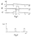
- FIG. 1 shows an output signal U A acquired by means of the method according to the invention over time.
- Figure 1a shows the influence of an interference signal on the output signal.
- the received interference signal level changes, whereupon the output voltage rises to a higher value and is then regulated back to setpoint value U S by time of the feedback loop until time t 2 .
- the diagram in FIG. 1a thus illustrates the operation of the feedback loop on the basis of an interference signal.
- FIG. 1b shows the case of the undisturbed detection of a useful signal pulse between the times t 3 and t 4 .
- the output signal U A is equal to its target value U S.
- the useful signal is therefore not falsified by any further interference signals.
- the situation is different in the example illustrated in FIG. 1c.
- the useful signal between times t 3 and t 4 is superimposed on an interference signal according to FIG. 1a.
- the measurement result is falsified between times t 3 and t 4 ; the output voltage U A is greater than the output voltage actually caused by the useful signal pulse.
- a control measurement is carried out at time t 5 and the output signal U A is measured and compared with the target value U S.
- the measurement is preferably carried out using an analog / digital converter and the evaluation is carried out using a logic circuit.
- the associated measurement here corresponding to the signal pulse, between the two points t 3 and t 4 , rejected.
- a control measurement can also be carried out before and after the useful signal pulse, so that it is ensured that an interference signal does not occur between t 5 and t 3 .
- Figure 2 shows an example in a different time scale than Figure 1 shows a useful signal pulse sequence.
- the useful signals can have a duration of approx. 100 ⁇ s for a signal period of 1 ms.
- the Specialist signal duration, signal period and signal form according to the respective applications of the invention choose the procedure.
- a typical application example are rain sensors for detection the degree of wetting of a glass pane, for example a motor vehicle windshield.
- the method according to the invention enables detection of useful signal pulses at more reliable and verifiable suppression of interference signals.
Landscapes
- Engineering & Computer Science (AREA)
- Power Engineering (AREA)
- Computer Networks & Wireless Communication (AREA)
- Signal Processing (AREA)
- Radar Systems Or Details Thereof (AREA)
- Investigating Or Analysing Materials By Optical Means (AREA)
- Geophysics And Detection Of Objects (AREA)
Applications Claiming Priority (2)
| Application Number | Priority Date | Filing Date | Title |
|---|---|---|---|
| DE1998160208 DE19860208A1 (de) | 1998-12-24 | 1998-12-24 | Verfahren zur Erfassung von störungsbehafteten Empfangssignalen |
| DE19860208 | 1998-12-25 |
Publications (3)
| Publication Number | Publication Date |
|---|---|
| EP1017191A2 true EP1017191A2 (fr) | 2000-07-05 |
| EP1017191A3 EP1017191A3 (fr) | 2004-03-10 |
| EP1017191B1 EP1017191B1 (fr) | 2006-05-24 |
Family
ID=7892760
Family Applications (1)
| Application Number | Title | Priority Date | Filing Date |
|---|---|---|---|
| EP19990125380 Expired - Lifetime EP1017191B1 (fr) | 1998-12-24 | 1999-12-20 | Procédé de discrimination des signaux reçus en présence de perturbation |
Country Status (2)
| Country | Link |
|---|---|
| EP (1) | EP1017191B1 (fr) |
| DE (2) | DE19860208A1 (fr) |
Family Cites Families (3)
| Publication number | Priority date | Publication date | Assignee | Title |
|---|---|---|---|---|
| DE3005949A1 (de) * | 1980-02-16 | 1981-09-03 | Horst Dipl.-Ing. Dr.-Ing. 8152 Feldkirchen-Westerham Spitzer | Elektronisches umlichtfilter |
| DE3336027A1 (de) * | 1983-10-04 | 1985-04-11 | Robert Bosch Gmbh, 7000 Stuttgart | Optoelektronischer empfaenger |
| JPH0746224A (ja) * | 1992-10-09 | 1995-02-14 | Philips Electron Nv | 送信システム及び受信機 |
-
1998
- 1998-12-24 DE DE1998160208 patent/DE19860208A1/de not_active Ceased
-
1999
- 1999-12-20 EP EP19990125380 patent/EP1017191B1/fr not_active Expired - Lifetime
- 1999-12-20 DE DE59913458T patent/DE59913458D1/de not_active Expired - Lifetime
Also Published As
| Publication number | Publication date |
|---|---|
| EP1017191B1 (fr) | 2006-05-24 |
| DE59913458D1 (de) | 2006-06-29 |
| EP1017191A3 (fr) | 2004-03-10 |
| DE19860208A1 (de) | 2000-06-29 |
Similar Documents
| Publication | Publication Date | Title |
|---|---|---|
| DE2816682C2 (fr) | ||
| EP0641679A1 (fr) | Dispositif de surveillance de pression du pneumatique d'un véhicule avec un palpeur | |
| EP0312524B1 (fr) | Procede et installation pour mesurer une distance par le traitement d'un signal optique a impulsions | |
| DE102010041693A1 (de) | Verfahren zum Prüfen der Funktionsfähigkeit eines photoelektrischen Rauchmelders | |
| DE2754420A1 (de) | Ballistische messanordnung | |
| DE3337041C1 (de) | Schaltungsvorrichtung zur Logarithmierung und Digitalisierung analoger Signale | |
| EP0664445A2 (fr) | Dispositif combiné pour déterminer la visibilité et la précipitation | |
| EP1017191A2 (fr) | Procédé de discrimination des signaux reçus en présence de perturbation | |
| DE102018126289A1 (de) | Verfahren zur Überprüfung der Lichtdurchlässigkeit wenigstens eines Fensters einer optischen Detektionsvorrichtung, optische Detektionsvorrichtung und Lichtdurchlässigkeitsüberprüfungseinrichtung | |
| DE3319431A1 (de) | Detektor zur erfassung von daten eines bewegten objekts und verfahren zu deren auswertung | |
| DE102007034606A1 (de) | System zum Erfassen optischer Signale mit einem Regensensor und Verfahren | |
| EP1014568B1 (fr) | Méthode et dispositif de détection d'un signal reçu comportant du bruit | |
| DE102005006402B3 (de) | Sensorvorrichtung und System | |
| DE3805328C2 (fr) | ||
| EP1544068B1 (fr) | Unité de mesure pour un capteur de pluie pour détecter l'humidité sur une surface et un capteur d'humidité | |
| DE102022201923B3 (de) | Verfahren und Schaltungsanordnung zur Ermittlung einer Induktivität einer Messspule und Verwendung dafür | |
| EP1526048B1 (fr) | Unité de mesure pour un capteur d'humidité permettant de détecter l'humidité sur une surface, capteur de pluie et méthode de détection d'humidité | |
| DE3906080C2 (fr) | ||
| DE202010018612U1 (de) | Lichtschranke | |
| DE2942953A1 (de) | Schaltungsanordnung zur induktivitaetsmessung | |
| CH683389A5 (de) | Verfahren zum Anbringen eines Kontaktelementes am Ende eines kunststoffisolierten elektrischen Leiters. | |
| EP2211205A2 (fr) | Procédé de détection d'objets dans une zone de surveillance et capteur optique destiné à l'exécution du procédé | |
| DE10348950A1 (de) | Verfahren zur Volumenbestimmung von kleinen bewegten kugelförmigen Objekten | |
| EP0973013A1 (fr) | Capteur de déplacement | |
| DE102007015920A1 (de) | Verfahren zur Entfernungsbestimmung mithilfe von pulsmodulierten Schallsignalen |
Legal Events
| Date | Code | Title | Description |
|---|---|---|---|
| PUAI | Public reference made under article 153(3) epc to a published international application that has entered the european phase |
Free format text: ORIGINAL CODE: 0009012 |
|
| AK | Designated contracting states |
Kind code of ref document: A2 Designated state(s): AT BE CH CY DE DK ES FI FR GB GR IE IT LI LU MC NL PT SE |
|
| AX | Request for extension of the european patent |
Free format text: AL;LT;LV;MK;RO;SI |
|
| PUAL | Search report despatched |
Free format text: ORIGINAL CODE: 0009013 |
|
| AK | Designated contracting states |
Kind code of ref document: A3 Designated state(s): AT BE CH CY DE DK ES FI FR GB GR IE IT LI LU MC NL PT SE |
|
| AX | Request for extension of the european patent |
Extension state: AL LT LV MK RO SI |
|
| 17P | Request for examination filed |
Effective date: 20040910 |
|
| AKX | Designation fees paid |
Designated state(s): DE FR GB IT |
|
| 17Q | First examination report despatched |
Effective date: 20041022 |
|
| GRAP | Despatch of communication of intention to grant a patent |
Free format text: ORIGINAL CODE: EPIDOSNIGR1 |
|
| GRAS | Grant fee paid |
Free format text: ORIGINAL CODE: EPIDOSNIGR3 |
|
| GRAA | (expected) grant |
Free format text: ORIGINAL CODE: 0009210 |
|
| AK | Designated contracting states |
Kind code of ref document: B1 Designated state(s): DE FR GB IT |
|
| REG | Reference to a national code |
Ref country code: GB Ref legal event code: FG4D Free format text: NOT ENGLISH |
|
| REF | Corresponds to: |
Ref document number: 59913458 Country of ref document: DE Date of ref document: 20060629 Kind code of ref document: P |
|
| GBT | Gb: translation of ep patent filed (gb section 77(6)(a)/1977) |
Effective date: 20060918 |
|
| ET | Fr: translation filed | ||
| PLBE | No opposition filed within time limit |
Free format text: ORIGINAL CODE: 0009261 |
|
| STAA | Information on the status of an ep patent application or granted ep patent |
Free format text: STATUS: NO OPPOSITION FILED WITHIN TIME LIMIT |
|
| 26N | No opposition filed |
Effective date: 20070227 |
|
| PGFP | Annual fee paid to national office [announced via postgrant information from national office to epo] |
Ref country code: IT Payment date: 20081227 Year of fee payment: 10 |
|
| PGFP | Annual fee paid to national office [announced via postgrant information from national office to epo] |
Ref country code: FR Payment date: 20081216 Year of fee payment: 10 |
|
| PGFP | Annual fee paid to national office [announced via postgrant information from national office to epo] |
Ref country code: GB Payment date: 20081219 Year of fee payment: 10 |
|
| GBPC | Gb: european patent ceased through non-payment of renewal fee |
Effective date: 20091220 |
|
| REG | Reference to a national code |
Ref country code: FR Ref legal event code: ST Effective date: 20100831 |
|
| PG25 | Lapsed in a contracting state [announced via postgrant information from national office to epo] |
Ref country code: FR Free format text: LAPSE BECAUSE OF NON-PAYMENT OF DUE FEES Effective date: 20091231 |
|
| PG25 | Lapsed in a contracting state [announced via postgrant information from national office to epo] |
Ref country code: GB Free format text: LAPSE BECAUSE OF NON-PAYMENT OF DUE FEES Effective date: 20091220 |
|
| PG25 | Lapsed in a contracting state [announced via postgrant information from national office to epo] |
Ref country code: IT Free format text: LAPSE BECAUSE OF NON-PAYMENT OF DUE FEES Effective date: 20091220 |
|
| PGFP | Annual fee paid to national office [announced via postgrant information from national office to epo] |
Ref country code: DE Payment date: 20160224 Year of fee payment: 17 |
|
| REG | Reference to a national code |
Ref country code: DE Ref legal event code: R119 Ref document number: 59913458 Country of ref document: DE |
|
| PG25 | Lapsed in a contracting state [announced via postgrant information from national office to epo] |
Ref country code: DE Free format text: LAPSE BECAUSE OF NON-PAYMENT OF DUE FEES Effective date: 20170701 |