EP1017628B1 - System zur wasserbehandlung mit dosierkontrolle - Google Patents
System zur wasserbehandlung mit dosierkontrolle Download PDFInfo
- Publication number
- EP1017628B1 EP1017628B1 EP98923710A EP98923710A EP1017628B1 EP 1017628 B1 EP1017628 B1 EP 1017628B1 EP 98923710 A EP98923710 A EP 98923710A EP 98923710 A EP98923710 A EP 98923710A EP 1017628 B1 EP1017628 B1 EP 1017628B1
- Authority
- EP
- European Patent Office
- Prior art keywords
- pump
- water
- water treatment
- valve
- hydraulically connected
- Prior art date
- Legal status (The legal status is an assumption and is not a legal conclusion. Google has not performed a legal analysis and makes no representation as to the accuracy of the status listed.)
- Revoked
Links
Images



Classifications
-
- C—CHEMISTRY; METALLURGY
- C02—TREATMENT OF WATER, WASTE WATER, SEWAGE, OR SLUDGE
- C02F—TREATMENT OF WATER, WASTE WATER, SEWAGE, OR SLUDGE
- C02F1/00—Treatment of water, waste water, or sewage
- C02F1/008—Control or steering systems not provided for elsewhere in subclass C02F
-
- C—CHEMISTRY; METALLURGY
- C02—TREATMENT OF WATER, WASTE WATER, SEWAGE, OR SLUDGE
- C02F—TREATMENT OF WATER, WASTE WATER, SEWAGE, OR SLUDGE
- C02F1/00—Treatment of water, waste water, or sewage
- C02F1/28—Treatment of water, waste water, or sewage by sorption
- C02F1/283—Treatment of water, waste water, or sewage by sorption using coal, charred products, or inorganic mixtures containing them
-
- C—CHEMISTRY; METALLURGY
- C02—TREATMENT OF WATER, WASTE WATER, SEWAGE, OR SLUDGE
- C02F—TREATMENT OF WATER, WASTE WATER, SEWAGE, OR SLUDGE
- C02F1/00—Treatment of water, waste water, or sewage
- C02F1/30—Treatment of water, waste water, or sewage by irradiation
- C02F1/32—Treatment of water, waste water, or sewage by irradiation with ultraviolet light
-
- C—CHEMISTRY; METALLURGY
- C02—TREATMENT OF WATER, WASTE WATER, SEWAGE, OR SLUDGE
- C02F—TREATMENT OF WATER, WASTE WATER, SEWAGE, OR SLUDGE
- C02F9/00—Multistage treatment of water, waste water or sewage
- C02F9/20—Portable or detachable small-scale multistage treatment devices, e.g. point of use or laboratory water purification systems
-
- G—PHYSICS
- G05—CONTROLLING; REGULATING
- G05D—SYSTEMS FOR CONTROLLING OR REGULATING NON-ELECTRIC VARIABLES
- G05D7/00—Control of flow
- G05D7/06—Control of flow characterised by the use of electric means
- G05D7/0617—Control of flow characterised by the use of electric means specially adapted for fluid materials
- G05D7/0629—Control of flow characterised by the use of electric means specially adapted for fluid materials characterised by the type of regulator means
- G05D7/0676—Control of flow characterised by the use of electric means specially adapted for fluid materials characterised by the type of regulator means by action on flow sources
-
- C—CHEMISTRY; METALLURGY
- C02—TREATMENT OF WATER, WASTE WATER, SEWAGE, OR SLUDGE
- C02F—TREATMENT OF WATER, WASTE WATER, SEWAGE, OR SLUDGE
- C02F2201/00—Apparatus for treatment of water, waste water or sewage
- C02F2201/002—Construction details of the apparatus
- C02F2201/006—Cartridges
Definitions
- the invention relates to a water treatment system and method and, more particularly, a water treatment system and method having improved dosing control for accurate distribution of treated water.
- High purity water is required for many applications including, for example, in chemical and biological analytical laboratories.
- Water for these applications is purified by a number of well-known techniques, including filtration, single or multiple distillation, sorption, and ion exchange.
- Water initially treated by distillation or reverse osmosis filtration is often further purified (polished) by passage through activated carbon beds to adsorb residual contaminants, principally organics.
- the pretreated water may also be treated by passage through layered or mixed beds of ion exchange resins to remove residual ionic impurities. Often, these water streams are also filtered through microporous filters to remove further residual contaminants prior to the system outlet.
- water treatment systems When purified water is not required, conventional water treatment systems typically recirculate the water in a continuous or periodic operation through the various water treatment devices included in the system, for example UV lamps, ion exchangers and ultrafilters, to prevent the water quality from deteriorating while standing. Because of the high energy costs incurred during continuous operation of a recirculation pump or the like, and the associated high noise levels which can be disturbing to nearby workers, water treatment systems arc often operated in a periodic mode of, for example, about 50 minutes standstill and 10 minutes of recirculation through the system. When purified water is required, therefore, it is sometimes necessary to circulate the water through the system for a period of time before the water can be used.
- control of the purified water flow rate from the system is typically performed by adjusting an outlet valve.
- the conventional system pump operates at a single high speed and output rate, to achieve the highest flow rate at the outlet valve, it can be difficult for users to dose small and/or accurate quantities of purified water from these systems.
- the present invention is directed to a water treatment system having dosing control, wherein water can be treated such that it has very low organic and ionic contamination, and can be accurately dispensed from the system.
- the water treatment system having dosing control includes a water inlet hydraulically connected to a pump having a variable speed motor. At least one water treatment device is hydraulically connected downstream of the pump, at least one outlet valve is hydraulically connected downstream of the water treatment unit, and a recirculation line is hydraulically connected from the outlet valve to the pump. The output of the pump is controlled by a regulating device connected to the variable speed motor.
- a water treatment system having dosing control includes a water inlet hydraulically connected to a pump. At least one water treatment device is hydraulically connected downstream of the pump, and at least one outlet valve is hydraulically connected downstream of the water treatment device, and a recirculation line is hydraulically connected from the outlet valve to the pump. A proportional valve is hydraulically connected downstream of said outlet valve, and the system output is controlled by a regulating device connected to the proportional valve.
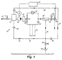
- a water treatment system 10 having dosing control of the present invention includes a water inlet having an inlet valve 11, for example in the form of a solenoid valve, connected to an untreated or retreated water line 12.
- This line can be hydraulically connected to a storage tank 14 downstream from inlet valve 11, to which the aspirating side of a pump 16 having a variable speed motor M is connected.
- the pump 16 passes the untreated or retreated water to at least one water treatment device that is hydraulically connected downstream of the pump.
- an ultraviolet (UV) lamp unit 18, a filter cartridge 22 having a plurality of series connected cartridges, for example, having at least one cartridge having at least one layer of an activated carbon and/or at least one layer of a mixture of ion exchange resins, and/or an ultrafilter (UF) unit 26, and combinations thereof can be used in the present system 10.
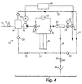
- Alternative embodiments of system 10 are shown in FIG. 2, wherein filter cartridge 22 is the only water treatment device; FIG. 3, wherein UV lamp unit 18 is connected upstream of filter cartridge 22; and FIG. 4, wherein UF unit 26 is connected downstream of filter cartridge 22.
- a disinfection unit 42 can also be hydraulically connected in system 10, positioned parallel with filter cartridge 22.
- a three-way valve 20 and a check valve 24 can be used to prevent disinfectant from unit 42 from entering filter cartridge 22.
- a conductivity measuring cell 28, which typically includes an integrated temperature sensor, can also be used in the system to monitor the water quality.
- a first recirculation line 32 is hydraulically connected from the outlet valve 30 to storage tank 14 through check valve 34, or directly to the aspirating side of pump 16. As shown in FIGS. 1 and 4, if UF unit 26 is used, the portion of the water which does not flow through unit 26 is directed to valve 38 at wastewater outlet 40, or it is directed to the aspirating side of pump 16 through outlet line 36 and a second recirculation line 31, having a throttle 33 and a check valve 35 upstream of solenoid valve 38. Recirculation line 32 is connected with outlet line 36 and circulation line 31 via connecting line 37 having a check valve 39.
- system 10 further includes a regulating device including an input device 44, to allow a user to set a flow rate, and a controller 46 (most typically, a CPU with memory).
- the input device 44 is in the form of, for example, a potentiometer, a key pad, an angle encoder, and the like. These devices typically include a rotating handle or key pad that is used to provide an input signal, for example the angle of rotation position, to controller 46 that represents a desired flow rate of water at outlet valve 30.
- the controller 46 converts the input signal to a motor control signal that causes the motor M to operate at a speed which drives pump 16 and causes the flow of water at outlet valve 30 to correspond to the desired flow rate.
- input device 44 can be positioned at any location throughout system 10 that is easily accessible for a user dispensing water. Therefore, the output of pump 16 is controlled by the user making, for example, rotating movements of an input device 44.
- the motor control signal causes the speed of motor M to vary between zero and a predetermined maximum speed, at which the highest output of pump 16 can be reached.
- the pump 16 is preferably a magnetically coupled positive displacement gear pump that is driven by motor M.
- motor M is preferably a variable speed motor, such as a 3-phase, brushless, electronically commutated direct current motor in a small power, low-voltage range, having an electronic drive, for example a VARIOTRONICTM compact drive electronic assembly (available from Papst-Motoren GmbH & Co. KG, Germany).
- VARIOTRONICTM compact drive electronic assembly available from Papst-Motoren GmbH & Co. KG, Germany.
- the regulating device can include a device that can function as a timer to turn off motor M at a first predetermined time, and/or turn on motor M at a second predetermined time.
- This operation would allow, for example, pump 16 to be preprogrammed to start up prior to normal hours of operation of water treatment system 10, and to shut down during extended periods of nonuse.
- a user would provide desired times of operation and shut down to the regulating device directly through an input device such as a key pad.
- the predetermined times for example, for starting up and shutting down motor M, are provided directly by the regulating device as a function of operational data.
- controller 46 of the regulating device is adaptable, and can be programmed to monitor usage characteristics and trends to predict use. For example, operational data, such as water volumes, flow rates, times and dates, and periods of operation can be gathered by controller 46 to draw inferences as to the motors operational schedule. It is possible, therefore, to run pump 16 at short time intervals or, preferably, continuously during standby mode with less noise, and lower operating cost, and provide high purity water that is readily available for use when outlet valve 30 is opened. When pump 16 is switched from the standby mode to a water dispensing mode by input device 44 of regulating device, the pump output rate can be adjusted in a stepwise manner or, preferably, essentially continuously up to a predetermined maximum output. This feature allows small quantities of water to be easily and accurately metered with a low pump output.
- the control of the output of pump 16 by the regulating device allows for better control of the pump output in the recirculation (or standby) mode when outlet valve 30 is closed, and maintains the treated water quality during the standby mode by circulating the water through the units 18, 22 and 26 for water treatment at a comparatively slow rate.
- water treatment by a UV lamp unit is effective at a 185 nm wavelength to reduce the TOC to levels of about 5 ppb, as well as at 254 nm wavelength to reduce bacteria levels.
- Water treatment by a filter cartridge having a plurality of series connected cartridges for example having at least one cartridge having at least one layer of an activated carbon, and at least one layer of a mixture of ion exchange resins, is known to be effective to adsorb residual organic contaminant materials as well as to remove residual ionic impurities.
- Water treatment by UF units is known to remove suspended small particles and pyrogens.
- outlet valve 30 can be switched between a completely closed and a completely open position.
- outlet valve 30 can be a solenoid valve which, starting from the closed position, is switched into the opened position during the initial phase of the movement of input device 44.
- the outflow rate of treated water from system 10 is determined by the output of pump 16 and not by the cross section of outlet valve 30.
- pump 16 when outlet valve 30 is closed, pump 16 is operated in the standby mode, at least in time intervals, at a comparatively low output.
- outlet valve 30 When outlet valve 30 is open, pump 16 is operated with an output whose lowest value is less than, and whose greatest value is higher than, the output in the standby mode.
- the water in system 10 In the water dispensing mode, the water in system 10 is initially brought to an approximate standstill, and can then be easily and accurately metered in small or large quantities by the user providing an input signal with input device 44.
- pump 16 can run at an output of about 0.5 liter/min; this output can be reduced or incrcased to about 1.5 liters/min when the system is dispensing water and outlet valve 30 is opened.
- the controller 46 When the system is returned to standby mode, by the input signal provided by the user, the controller 46 provides a motor control signal that causes the motor M to initially stop and then operate at a speed which causes pump 16 to recirculate water through the system.
- system 10 can include an inlet valve 11, for example a solenoid valve, that is either directly connected to an untreated public water supply system, or a retreated (for example, by reverse osmosis) water line 12.
- System 10 can also include storage tank 14, positioned between inlet valve 11 and pump 16, into which recirculation line 32 is hydraulically connected. If used, inlet valve 11 is opened simultaneously with outlet valve 30. Alternatively, inlet valve 11 can be used to control the liquid level of storage tank 14.
- disinfecting unit 42 through which at least one disinfectant can be introduced into the water flowing through system 10, is hydraulically connected between pump 16 and outlet valve 30.
- Disinfecting unit 42 can be used to disinfect water-contacting elements of system 10.
- certain water treatment units for example filter cartridge 22 including at least one layer of a mixture of ion exchange resins, can be isolated from the system, by operation of valve 20 and check valve 24, prior to the start of a disinfecting process.
- disinfectants typically include oxidants which can adversely affect cation and anion exchange resins, resulting in a loss of the ion exchange resins capacity.
- FIG. 5 An alternative embodiment of the water treatment system of the present invention is shown in FIG. 5. This system is similar to that shown in FIG. 1 and described above.
- an input device 44 which can be in the form of, for example, a potentiometer, a keypad, an angle encoder, and the like, is used to provide an input signal to controller 46 that represents a desired flow rate of water.
- the controller 46 converts the input signal from input device 44 to a valve control signal, which controls the outflow cross-section of valve 48 and causes the flow of water at the valve to correspond to the desired flow rate.
- input device 44 can be positioned in any location throughout the system that is easily accessible for a user dispensing water.
- valve 48 causes the valve 48 cross-section to vary between 0 and a predetermined maximum opening, at which the highest output of the system can be achieved.
- Valve 48 is preferably a proportional valve which opens proportionally in response to a particular applied voltage.
- the valve's internal structure is lined with an inert plastic material to prevent water contamination at the system outlet.
- proportional valves are commercially available, for example, from South Bend Controls, Inc. (South Bend, IN); or Skinner Valve, Honeywell, Inc. (New England, CT).
- the output of system 10 therefore, can be controlled by the user making, for example, rotating movements of an input device 44 to control outflow cross-section of valve 48 and/or the speed of motor M.
- FIG. 6 graphically illustrates the outflow rates of a conventional system and that of the present invention.
- line 50 is a curve of the outflow rate of a conventional system over the opening and closing angle of the outlet valve.
- Line 52 represents the outflow rate of the present system as a function of the angle of rotation position of input device 44.
- line 50 indicates that a circulating pump is operated continuously, or at intervals, to achieve a maximum outflow rate when the outlet valve is completely opened.
- a high water pressure is initially present at the outlet valve, as shown by the steep rise of line 50, which indicates that small amounts of water can be difficult to easily and accurately meter.
- the outflow rates of the present system can be controlled, as represented by line 52.
- Increasing movement of input device 44 corresponds to a proportional rise of the outflow rate.
- the outflow rate begins to rise only after an angle of rotation of input device 44 of about 10% of the entire opening angle.
- the initial output of pump 16 is lowered to zero from the level of the standby mode, outlet valve 30 is then completely opened, and the output of pump 16 is subsequently increased during further adjustment of input device 44.
- Another aspect of the present invention includes incorporating a ventilation system on filter cartridge assembly 22.
- the filter cartridge assembly 22 can include a plurality of series connected cartridges.
- Each of the cartridges typically include an outer housing, a top end cap, a bottom end cap, and a central return tube.
- the top and bottom end caps are secured to opposite ends of the housing, while the return tube extends between, and is connected to, the top and bottom end caps.
- the housing is typically filled with filtering media, which includes, for example, at least one layer of an activated carbon and/or at least one layer of a mixture of ion exchange resins, which is placed around the return tube and is retained within the housing by the top and bottom end caps.
- Water to be treated enters the filter cartridge through an inlet port and an inlet plenum located in the top end cap.
- the water is then directed into the housing through an upper flow distributor in the top end cap which uniformly distributes the water into the filter media.
- the water permeates down through the filtering media to the bottom of the housing where it passes through a lower flow distributor and collects in a product collection plenum in the bottom end cap.
- the water is then directed upwardly from the product collection plenum through the return tube into the top end cap from which the purified water is discharged through an outlet port.
- a water treatment system having dosing control was evaluated to determine the effectiveness of the system in providing pure water, substantially free of contaminants, which can be accurately dosed at the system outlet when desired, or recirculated throughout the system at lower motor speeds and lower noise levels.
- Pretreated water by reverse osmosis having a conductivity of about 2.0 ⁇ S/cm was introduced to the system through a on/off solenoid valve (lined with an inert material) at a flow rate of about 1.5 liters per minute.
- the feed water was then introduced to a magnetically coupled positive displacement gear pump (available from Tuthill, Inc.) to pressurize the water up to about 4 bars.
- the pump was driven by a VARIOTRONICTM variable speed motor and motor controller.
- the pump then passed the water through a series of water treatment devices.
- the first device was a 185 nm one-pass UV lamp unit (available from Ideal Horizons, Inc., Poultney, VT). The UV lamp unit was used to oxidize organic contaminants present in the water.
- the water was then fed to a second device, which was a filter cartridge assembly (available from United States Filter Corporation, Lowell, MA) that included four individual filter cartridges hydraulically connected in series, and contained at least one layer of an activated carbon and/or at least one layer of a mixture of ion exchange resins.
- the filter cartridge assembly was used to remove residual organic and ionic impurities.
- the water was then passed through an electrical resistivity sensor which measured the resistivity of the water to be about 18.3 megohm-cm (0.054 ⁇ S/cm).
- the water was then passed through a 10,000 molecular weight cutoff polysulfone hollow fiber membrane ultrafilter, wherein at least about 90 percent of the water passed through, while the reject stream was recycled to the pump inlet.
- a 0.22 ⁇ m membrane final filter made from a cellulose nitrate membrane available from Gelman Sciences, Ann Arbor, MI, was used to remove any remaining microorganisms and/or particles in the water.
- the output of the motor, which drives the pump was controlled by an input device in the form of a potentiometer having a rotating handle that can be adjusted up to 300°.
- the potentiometer provided an input signal, which represents a desired flow rate of water at the outlet of the system, to a microprocessor.
- the microprocessor converted the input signal from the potentiometer to a motor control signal, which was sent to the VARIOTRONICTM motor controller which caused the VARIOTRONICTM motor to operate at a speed which caused the pump to pass the water through the system to the outlet valve at the desired flow rate.
- This flow rate was adjustable between a range of 0 to about 1.5 liters per minute at increments as small as a few drops of water to allow for accurate dosing of purified water.
- the pump was operated in a recirculation mode, and the water was recirculated at a flow rate of about 0.5 liters per minute through the system to maintain the high level of water purity.
- the system was also provided with a sanitization cycle.
- the sanitization cycle was intended to he used to maintain a low microorganism population within the system despite the fact that the system components (the conduits, valves, and connectors) were made from inert materials in terms of extractables or leachables.
- the sanitization cycle was started by introducing a chlorine sanitization tablet (available from United States Filter Corporation, Lowell, MA), typically made from a chemical oxidant such as chloroisocyanuric acid, or the like, into a sanitization chamber which was then dissolved in the flow stream of water.
- a chlorine sanitization tablet available from United States Filter Corporation, Lowell, MA
- a chemical oxidant such as chloroisocyanuric acid, or the like
- the chemical oxidant then passed through the system to sanitize the internal tubing, fittings, pump, UV lamp unit and UF membrane.
- the filter cartridge assembly was isolated because the chemical oxidant used in the sanitization cycle is detrimental to the ion exchange resin in the filter cartridges.
- the noise level of the system was measured to determine the actual reduced noise level resulting from the use of a variable speed motor.
- a Radio ShackTM sound level meter was used in determining the noise levels, which were measured at 0.5 and 1.0 meter from the front of the water treatment system in both recirculation (0.5 liters per minute) and at full production (1.5 liters per minute).
- the measured noise level from the system was 63.5 dB at 0.5 meter and 54.0 dB at 1.0 meter.
- the measured noise level from the system was 68.0 dB at 0.5 meter and 64.0 dB at 1.0 meter.
- the background noise for each test was less than about 50 dB at both 0.5 and 1.0 meter.
- This Example illustrates the effectiveness of the present system in providing pure water, substantially free of both organic and ionic contaminants, which can be accurately distributed as a desired product flow rate.
- the Example illustrates that water can be effectively and continuously purified in a recirculation mode at lower pump outputs (motor speed) resulting in substantially reduced noise levels.
- system 10 can include additional or alternative water treatment devices such as dialysis units, continuous electrodeionization units, reverse osmosis units, other types of media filters, and the like.
- the dosing control feature of the present invention can be applied to larger systems having higher flow rates in a wide variety of industrial applications such as in pharmaceuticals, electronics, food and beverage applications, chemical processing, wastewater and municipal water treatment, as well as analytical applications.
- a device which is to be supplied with ultra-pure water can be fixedly connected, for example by means of a hose (not shown), to the outlet valve 30, or valve 48 (FIG. 5).
- a dispensing unit may also be provided in system 10 to make accurate water dosing more convenient for the user.
- Another modification to system 10 contemplated by the present invention is the provision of a remote control of the input device 44 to control the motor M and/or valve 48, or providing an input device at various locations in the system, for example at a central switchboard. Accordingly, the invention is not to be limited except as by the appended claims.
Landscapes
- Engineering & Computer Science (AREA)
- Organic Chemistry (AREA)
- Life Sciences & Earth Sciences (AREA)
- Hydrology & Water Resources (AREA)
- Environmental & Geological Engineering (AREA)
- Water Supply & Treatment (AREA)
- Chemical & Material Sciences (AREA)
- Health & Medical Sciences (AREA)
- General Physics & Mathematics (AREA)
- Physics & Mathematics (AREA)
- Clinical Laboratory Science (AREA)
- Automation & Control Theory (AREA)
- Toxicology (AREA)
- Water Treatment By Sorption (AREA)
- Separation Using Semi-Permeable Membranes (AREA)
- Treatment Of Water By Ion Exchange (AREA)
- Pharmaceuticals Containing Other Organic And Inorganic Compounds (AREA)
- Medicinal Preparation (AREA)
- Medicines Containing Material From Animals Or Micro-Organisms (AREA)
- Physical Water Treatments (AREA)
- Flow Control (AREA)
Claims (20)
- Ein Wasserbehandlungssystem (10) mit Dosierregelung, das Folgendes umfasst:wobei der Pumpenausstoß durch eine Reguliervorrichtung geregelt wird, die an den Regelmotor angeschlossen ist;einen Wassereinlass (12), der hydraulisch an einer Pumpe (16) angeschlossen ist, die einen Regelmotor (M) aufweist und einen Pumpenausstoß erzeugt;mindestens eine Wasserbehandlungsvorrichtung (18, 22, 26), die stromabwärts von der Pumpe (16) hydraulisch angeschlossen ist;mindestens ein Auslassventil (30), das stromabwärts von der Wasserbehandlungsvorrichtung hydraulisch angeschlossen ist; undeine Rückführungsleitung (32), die von dem Auslassventil (30) an der Pumpe (16) hydraulisch angeschlossen ist,
die Reguliervorrichtung einen Regler (46) und eine Eingabevorrichtung (44) beinhaltet, um dem Regler (46) ein Eingabesignal, das eine erwünschte Strömungsgeschwindigkeit an dem Auslassventil (30) darstellt, bereitzustellen; und
der Regler (46) das Eingabesignal in ein Motorsteuersignal umwandelt, das den Regelmotor (M) dazu veranlasst, bei einer Geschwindigkeit zu laufen, die dazu führt, dass die Wasserströmung an dem Auslassventil (30) mit der erwünschten Strömungsgeschwindigkeit übereinstimmt. - System gemäß Anspruch 1, das ferner ein Proportionalventil (48) beinhaltet, das stromabwärts des Auslassventils (30) hydraulisch angeschlossen ist, wobei die Reguliervorrichtung an dem Proportionalventil (48) angeschlossen ist.
- System gemäß Anspruch 2, wobei der Regler (46) das Eingabesignal in ein Ventilsteuersignal umwandelt, das dazu führt, dass sich das Proportionalventil (48) an einem Querschnitt öffnet, was dazu führt, dass die Wasserströmung an dem Proportionalventil (48) der erwünschten Strömungsgeschwindigkeit entspricht.
- Ein Wasserbehandlungssystem (10) mit Dosierregelung, um einen Systemausstoß zu regulieren, wobei das Wasserbehandlungssystem (10) Folgendes umfasst:einen Wassereinlass (12), der hydraulisch an einer Pumpe (16) angeschlossen ist;mindestens eine Wasserbehandlungsvorrichtung (18, 22, 26), die stromabwärts der Pumpe (16) hydraulisch angeschlossen ist;mindestens ein Auslassventil (30), das stromabwärts der Wasserbehandlungsvorrichtung hydraulisch angeschlossen ist;eine Rückführungsleitung (32), die von dem Auslassventil (30) hydraulisch an der Pumpe (16) angeschlossen ist; undein Proportionalventil (48), das stromabwärts des Auslassventils hydraulisch angeschlossen ist, wobei der Systemausstoß durch eine Reguliervorrichtung geregelt wird, die an dem Proportionalventil (48) angeschlossen ist;die Reguliervorrichtung einen Regler (46) und eine Eingabevorrichtung (44) beinhaltet, um dem Regler (46) ein Eingabesignal, das eine erwünschte Strömungsgeschwindigkeit an dem Proportionalventil (48) darstellt, bereitzustellen; undder Regler (46) das Eingabesignal in ein Ventilsteuersignal umwandelt, das dazu führt, dass das Proportionalventil (48) sich an einem Querschnitt öffnet, was dazu führt, dass die Wasserströmung an dem Proportionalventil (48) der erwünschten Strömungsgeschwindigkeit entspricht.
- System gemäß Anspruch 2, wobei die Pumpe (16) einen Regelmotor (M) aufweist.
- System gemäß einem der Ansprüche 1 bis 5, wobei mindestens eine Wasserbehandlungsvorrichtung aus der Gruppe gewählt wird, die aus einer Ultraviolettlicht-Lampeneinheit (18), einer Filterpatrone (22) mit mindestens einer Schicht Aktivkohle und mindestens einer Schicht aus einer Mischung von lonenaustauschharzen, einer Ultrafiltereinheit (26) und Kombinationen hieraus besteht.
- System gemäß Anspruch 6, wobei die Wasserbehandlungsvorrichtung eine Ultraviolettlicht-Lampeneinheit (18) ist.
- System gemäß Anspruch 6, wobei die Wasserbehandlungsvorrichtung eine Filterpatrone (22) ist, die mindestens eine Schicht Aktivkohle und mindestens eine Schicht einer Mischung aus lonaustauschharzen aufweist.
- System gemäß Anspruch 6, wobei die Wasserbehandlungsvorrichtung eine Ultrafiltereinheit (26) ist.
- System gemäß einem der vorhergehenden Ansprüche, das ferner eine Desinfektionseinheit (42) umfasst, die zwischen der Pumpe (16) und dem Auslassventil (30) hydraulisch angeschlossen ist.
- System gemäß einem der vorhergehenden Ansprüche, wobei das Auslassventil (30) sich während der Wasserrückführung im System in völlig geschlossener Position befindet, und sich zum Entfernen des gereinigten Wassers aus dem System in völlig geöffneter Position befindet.
- System gemäß Anspruch 11, wobei die Pumpe (16) einen Ausstoß von ungefähr 0,5 Litern/min zur Wasserrückführung im System hat, wenn das Auslassventil (30) geschlossen ist.
- System gemäß Anspruch 11 oder Anspruch 12, wobei der Pumpenausstoß durch die Reguliervorrichtung geregelt wird, wenn das Auslassventil (30) geöffnet ist.
- System gemäß einem der vorhergehenden Ansprüche, wobei die Eingabevorrichtung (44) einen Potentiometer beinhaltet.
- System gemäß einem der vorhergehenden Ansprüche, wobei die Eingabevorrichtung (44) eine Kleintastatur beinhaltet.
- System gemäß einem der vorhergehenden Ansprüche, wobei die Eingabevorrichtung (44) einen Winkelcodierer beinhaltet.
- System gemäß einem der vorhergehenden Ansprüche, wobei die Reguliervorrichtung ein Potentiometer ist.
- System gemäß einem der vorhergehenden Ansprüche, wobei die Reguliervorrichtung eine Vorrichtung beinhaltet, die mindestens ein Abschalten des Motors zu einem vorbestimmten Zeitpunkt und ein Einschalten des Motors an einem zweiten vorbestimmten Zeitpunkt durchführt.
- System gemäß Anspruch 18 oder Anspruch 19, wobei der erste und zweite vorbestimmte Zeitpunkt von einem Benutzer durch eine Eingabevorrichtung bereitgestellt wird.
- System gemäß Anspruch 18 oder Anspruch 19, wobei der erste und zweite vorbestimmte Zeitpunkt von einer Reguliervorrichtung als eine Funktion von Betriebsdaten bereitgestellt wird.
Applications Claiming Priority (3)
| Application Number | Priority Date | Filing Date | Title |
|---|---|---|---|
| US08/859,340 US5925240A (en) | 1997-05-20 | 1997-05-20 | Water treatment system having dosing control |
| US859340 | 1997-05-20 | ||
| PCT/US1998/010568 WO1998052874A2 (en) | 1997-05-20 | 1998-05-20 | Water treatment system having dosing control |
Publications (2)
| Publication Number | Publication Date |
|---|---|
| EP1017628A2 EP1017628A2 (de) | 2000-07-12 |
| EP1017628B1 true EP1017628B1 (de) | 2002-10-30 |
Family
ID=25330672
Family Applications (1)
| Application Number | Title | Priority Date | Filing Date |
|---|---|---|---|
| EP98923710A Revoked EP1017628B1 (de) | 1997-05-20 | 1998-05-20 | System zur wasserbehandlung mit dosierkontrolle |
Country Status (6)
| Country | Link |
|---|---|
| US (1) | US5925240A (de) |
| EP (1) | EP1017628B1 (de) |
| JP (1) | JP2002502307A (de) |
| AT (1) | ATE226921T1 (de) |
| DE (1) | DE69809079T2 (de) |
| WO (1) | WO1998052874A2 (de) |
Cited By (1)
| Publication number | Priority date | Publication date | Assignee | Title |
|---|---|---|---|---|
| CN104291465A (zh) * | 2014-09-27 | 2015-01-21 | 姚健军 | 循环水处理设备 |
Families Citing this family (87)
| Publication number | Priority date | Publication date | Assignee | Title |
|---|---|---|---|---|
| US6398965B1 (en) | 1998-03-31 | 2002-06-04 | United States Filter Corporation | Water treatment system and process |
| US6328896B1 (en) | 1998-04-24 | 2001-12-11 | United States Filter Corporation | Process for removing strong oxidizing agents from liquids |
| JP4472050B2 (ja) * | 1998-10-20 | 2010-06-02 | 日東電工株式会社 | 造水装置および造水方法 |
| KR100304703B1 (ko) * | 1999-02-09 | 2001-09-26 | 윤종용 | 필터의 기능을 감지하는 제어기를 갖는 반도체소자의 제조장비 |
| EP1210158A4 (de) * | 1999-07-13 | 2003-02-12 | Hammonds Technical Serv Inc | Vorrichtung und verfahren zur chlorung |
| US6264836B1 (en) | 1999-10-21 | 2001-07-24 | Robert M. Lantis | Method and apparatus for decontaminating fluids using ultraviolet radiation |
| MY120639A (en) * | 2000-01-21 | 2005-11-30 | Lightstream Technologies Inc | Method and apparatus for decontaminating fluids using ultraviolet radiation |
| GB0001439D0 (en) * | 2000-01-21 | 2000-03-08 | R P Adam Limited | Method of controlling microbiological activity in water storage tanks and apparatus for use in such method |
| US6328881B1 (en) | 2000-03-08 | 2001-12-11 | Barnstead Thermolyne Corporation | Water purification system and method including dispensed volume sensing and control |
| US6379560B1 (en) | 2000-03-08 | 2002-04-30 | Barnstead/Thermodyne Corporation | Water purifying apparatus and method for purifying water |
| USRE40310E1 (en) | 2000-03-08 | 2008-05-13 | Barnstead Thermolyne Corporation | Water purification system and method including dispensed volume sensing and control |
| GB0016846D0 (en) * | 2000-07-10 | 2000-08-30 | United States Filter Corp | Electrodeionisation Apparatus |
| US7147785B2 (en) | 2000-09-28 | 2006-12-12 | Usfilter Corporation | Electrodeionization device and methods of use |
| US6520545B2 (en) | 2000-12-08 | 2003-02-18 | Sartorius Ag | Fluid connection adapter assembly |
| US6383382B1 (en) * | 2000-12-08 | 2002-05-07 | Sartorius Ag | Dual cartridge media housing |
| US6607647B2 (en) | 2001-04-25 | 2003-08-19 | United States Filter Corporation | Electrodeionization apparatus with expanded conductive mesh electrode and method |
| US6649037B2 (en) | 2001-05-29 | 2003-11-18 | United States Filter Corporation | Electrodeionization apparatus and method |
| US6579445B2 (en) | 2001-06-01 | 2003-06-17 | Sartorius Ag | System for the production of laboratory grade ultrapure water |
| ATE497830T1 (de) | 2001-10-15 | 2011-02-15 | Siemens Water Tech Holdg Corp | Vorrichtung und verfahren zur reinigung von flüssigkeiten |
| DE60234043D1 (de) * | 2001-11-05 | 2009-11-26 | Bionomics Ltd | Vorrichtung und verfahren zur herstellung von wasser hoher mikrobiologischer reinheit mit hilfe einer umkehrosmose-membrananlage |
| GB0205893D0 (en) * | 2002-03-13 | 2002-04-24 | Otv Sa | Water purification apparatus |
| US7501061B2 (en) | 2002-10-23 | 2009-03-10 | Siemens Water Technologies Holding Corp. | Production of water for injection using reverse osmosis |
| US6929748B2 (en) * | 2003-03-28 | 2005-08-16 | Chemitreat Pte Ltd | Apparatus and method for continuous electrodeionization |
| US7779781B2 (en) | 2003-07-31 | 2010-08-24 | Asml Netherlands B.V. | Lithographic apparatus and device manufacturing method |
| US7326325B2 (en) * | 2003-09-19 | 2008-02-05 | Siemens Water Technologies Holding Corp. | Apparatus and method for connecting water treatment devices |
| US7846340B2 (en) | 2003-11-13 | 2010-12-07 | Siemens Water Technologies Corp. | Water treatment system and method |
| US7582198B2 (en) | 2003-11-13 | 2009-09-01 | Siemens Water Technologies Holding Corp. | Water treatment system and method |
| US7563351B2 (en) | 2003-11-13 | 2009-07-21 | Siemens Water Technologies Holding Corp. | Water treatment system and method |
| US7083733B2 (en) * | 2003-11-13 | 2006-08-01 | Usfilter Corporation | Water treatment system and method |
| US7862700B2 (en) | 2003-11-13 | 2011-01-04 | Siemens Water Technologies Holding Corp. | Water treatment system and method |
| US20050103717A1 (en) | 2003-11-13 | 2005-05-19 | United States Filter Corporation | Water treatment system and method |
| US7604725B2 (en) | 2003-11-13 | 2009-10-20 | Siemens Water Technologies Holding Corp. | Water treatment system and method |
| US8377279B2 (en) | 2003-11-13 | 2013-02-19 | Siemens Industry, Inc. | Water treatment system and method |
| US7100427B2 (en) * | 2004-05-07 | 2006-09-05 | Sensicore, Inc. | Multi-sensor system for fluid monitoring with selective exposure of sensors |
| US7249000B2 (en) * | 2004-05-07 | 2007-07-24 | Sensicore, Inc. | Fluid monitoring systems and methods with data communication to interested parties |
| US7104115B2 (en) * | 2004-05-07 | 2006-09-12 | Sensicore, Inc. | Fluid treatment apparatus with input and output fluid sensing |
| US20050251366A1 (en) * | 2004-05-07 | 2005-11-10 | Sensicore, Inc. | Monitoring systems and methods for fluid testing |
| US7329358B2 (en) | 2004-05-27 | 2008-02-12 | Siemens Water Technologies Holding Corp. | Water treatment process |
| US7959780B2 (en) | 2004-07-26 | 2011-06-14 | Emporia Capital Funding Llc | Textured ion exchange membranes |
| WO2006020784A1 (en) * | 2004-08-09 | 2006-02-23 | Sensicore, Inc. | Systems and methods for fluid quality monitoring using portable sensors in connection with supply and service entities |
| US7442297B2 (en) * | 2005-02-28 | 2008-10-28 | Barnstead/Thermolyne Corp. | Remote water dispensing device and methods for operating such remote water dispensing devices |
| US7658828B2 (en) | 2005-04-13 | 2010-02-09 | Siemens Water Technologies Holding Corp. | Regeneration of adsorption media within electrical purification apparatuses |
| US8045849B2 (en) * | 2005-06-01 | 2011-10-25 | Siemens Industry, Inc. | Water treatment system and process |
| US7424399B2 (en) * | 2005-06-10 | 2008-09-09 | Ge Analytical Instruments, Inc. | Systems and methods for fluid quality sensing, data sharing and data visualization |
| US7780833B2 (en) | 2005-07-26 | 2010-08-24 | John Hawkins | Electrochemical ion exchange with textured membranes and cartridge |
| BRPI0616890A2 (pt) | 2005-10-06 | 2011-07-05 | Pionetics Corp | aparelho de tratamento de fluido, e, métodos de tratamento de um fluido, de filtração de fluido em uma célula eletroquìmica, e de operação de uma célula eletroquìmica |
| FR2896793B1 (fr) | 2006-01-27 | 2008-08-08 | Millipore Corp | Systeme et procede de purification d'eau |
| FR2896792B1 (fr) | 2006-01-27 | 2008-07-18 | Millipore Corp | Systeme et procede de purification d'eau |
| US10252923B2 (en) | 2006-06-13 | 2019-04-09 | Evoqua Water Technologies Llc | Method and system for water treatment |
| US10213744B2 (en) | 2006-06-13 | 2019-02-26 | Evoqua Water Technologies Llc | Method and system for water treatment |
| US8277627B2 (en) | 2006-06-13 | 2012-10-02 | Siemens Industry, Inc. | Method and system for irrigation |
| JP4831480B2 (ja) * | 2006-06-21 | 2011-12-07 | 三浦工業株式会社 | 膜濾過システム |
| US20080067069A1 (en) | 2006-06-22 | 2008-03-20 | Siemens Water Technologies Corp. | Low scale potential water treatment |
| US7820024B2 (en) | 2006-06-23 | 2010-10-26 | Siemens Water Technologies Corp. | Electrically-driven separation apparatus |
| US7744760B2 (en) | 2006-09-20 | 2010-06-29 | Siemens Water Technologies Corp. | Method and apparatus for desalination |
| US7824543B2 (en) * | 2006-09-29 | 2010-11-02 | Barnstead Themolyne Corporation | Wireless water purification systems and wireless remote dispensing devices for water purification systems |
| US7699993B2 (en) * | 2006-09-29 | 2010-04-20 | Barnstead Thermolyne Corporation | Methods for wirelessly operating water purification systems |
| MX2010005876A (es) | 2007-11-30 | 2010-06-15 | Siemens Water Tech Corp | Sistemas y metodos para tratamiento de agua. |
| DE102008002727B4 (de) | 2008-06-27 | 2020-12-17 | Brita Gmbh | Vorrichtung zur Behandlung von Wasser, insbesondere Filtervorrichtung, und Kartusche |
| DE102008040335B4 (de) | 2008-07-10 | 2013-05-08 | Brita Gmbh | Vorrichtung zur Entkeimung von Wasser und Verwendung derselben |
| GB0818922D0 (en) * | 2008-10-16 | 2008-11-19 | Otv Sa | Component, method and system of sanitising a water purification apparatus and/or a distribution apparatus |
| GB0818920D0 (en) * | 2008-10-16 | 2008-11-19 | Otv Sa | Water purification apparatus and method |
| GB0818924D0 (en) * | 2008-10-16 | 2008-11-19 | Otv Sa | Water purification apparatus |
| DE102009040142A1 (de) * | 2009-09-04 | 2011-03-10 | Krones Ag | Verfahren und Anlage zum Filtrieren von Wasser, insbesondere Ultrafiltrationsverfahren |
| TWD148182S1 (zh) | 2011-04-01 | 2012-07-11 | 布利塔有限公司 | 紫外線輻射裝置 |
| US9010361B2 (en) | 2011-10-27 | 2015-04-21 | Pentair Residential Filtration, Llc | Control valve assembly |
| US9695070B2 (en) | 2011-10-27 | 2017-07-04 | Pentair Residential Filtration, Llc | Regeneration of a capacitive deionization system |
| US8961770B2 (en) | 2011-10-27 | 2015-02-24 | Pentair Residential Filtration, Llc | Controller and method of operation of a capacitive deionization system |
| US8671985B2 (en) | 2011-10-27 | 2014-03-18 | Pentair Residential Filtration, Llc | Control valve assembly |
| US9637397B2 (en) | 2011-10-27 | 2017-05-02 | Pentair Residential Filtration, Llc | Ion removal using a capacitive deionization system |
| TWI485291B (zh) * | 2012-09-28 | 2015-05-21 | Morinaga Milk Industry Co Ltd | 電解水製造裝置、電解水之製造方法及電解槽 |
| TWI531541B (zh) * | 2014-08-26 | 2016-05-01 | 恆達智能科技股份有限公司 | 逆滲透淨水處理方法及其系統 |
| CN104291466B (zh) * | 2014-09-27 | 2016-08-24 | 吴玲玲 | 水处理设备 |
| US9757695B2 (en) | 2015-01-03 | 2017-09-12 | Pionetics Corporation | Anti-scale electrochemical apparatus with water-splitting ion exchange membrane |
| CN104891736B (zh) * | 2015-01-30 | 2017-03-01 | 郑州航空港区格威特污水净化有限公司 | 一种环保污水处理装置 |
| JP2018509287A (ja) * | 2015-03-13 | 2018-04-05 | ザ クリーヴランド クリニック ファウンデーションThe Cleveland Clinic Foundation | 滅菌及び/又は浄化された流体及び/又は溶液の配送システム |
| TWI614060B (zh) * | 2016-12-02 | 2018-02-11 | 恆達智能科技股份有限公司 | 用於逆滲透淨水處理之幫浦裝置 |
| RU2641923C1 (ru) * | 2017-01-09 | 2018-01-23 | Общество с ограниченной ответственностью "ВОДОРОБОТ" | Водоочистительная установка |
| JP7154277B2 (ja) | 2017-08-21 | 2022-10-17 | エヴォクア ウォーター テクノロジーズ エルエルシー | 農業用および飲料用の塩水の処理 |
| US12180103B2 (en) | 2017-08-21 | 2024-12-31 | Evoqua Water Technologies Llc | Treatment of saline water for agricultural and potable use and for generation of disinfectant solution |
| US20190309873A1 (en) * | 2018-04-06 | 2019-10-10 | Tomar Water Systems, Inc. | Actuated valve mechanism for fluid flow control |
| GB201817874D0 (en) | 2018-11-01 | 2018-12-19 | Vws Uk Ltd | A portable water purifying and dispensing unit |
| CN120659941A (zh) | 2022-12-09 | 2025-09-16 | 默克专利股份公司 | 用于液体分配单元的阀组件及用于水净化系统的液体分配单元 |
| USD987029S1 (en) * | 2023-02-03 | 2023-05-23 | Spot Zero Reverse Osmosis Inc. | Portable reverse osmosis system |
| EP4683890A1 (de) | 2023-03-23 | 2026-01-28 | Merck Patent GmbH | Abgabevorrichtung für gereinigtes wasser |
| CN118684308A (zh) * | 2024-07-22 | 2024-09-24 | 中煤科工集团重庆研究院有限公司 | 一种液压驱动控制的陶瓷膜过滤系统 |
| USD1112605S1 (en) | 2024-10-18 | 2026-02-10 | Spot Zero Reverse Osmosis Inc. | Portable reverse osmosis system |
Family Cites Families (59)
| Publication number | Priority date | Publication date | Assignee | Title |
|---|---|---|---|---|
| US526695A (en) * | 1894-10-02 | emery | ||
| US844438A (en) * | 1906-07-28 | 1907-02-19 | Cummings Filter Co | Filtering apparatus. |
| US1942584A (en) * | 1932-06-22 | 1934-01-09 | Weinstein Joseph | Filter |
| US2391716A (en) * | 1943-05-07 | 1945-12-25 | Infilco Inc | Filter |
| US2752309A (en) * | 1952-04-30 | 1956-06-26 | Ardath H Emmons | Process for water decontamination |
| US2809753A (en) * | 1955-06-07 | 1957-10-15 | Herbert J Atkinson | Continuous filtering apparatus for flowing liquids |
| GB928553A (en) * | 1961-11-06 | 1963-06-12 | Roosa Vernon D | Filter assembly |
| US3155612A (en) * | 1962-05-02 | 1964-11-03 | Union Tank Car Co | Fluid distributor for tanks |
| US3171801A (en) * | 1962-10-29 | 1965-03-02 | Gen Services Company | Process for clarifying water |
| US3266628A (en) * | 1964-02-21 | 1966-08-16 | Reid Mfg Inc | Flexible impervious cartridge filter |
| US3716143A (en) * | 1970-03-30 | 1973-02-13 | Aqua Chem Inc | Reverse osmosis separation apparatus |
| US4088563A (en) * | 1970-06-16 | 1978-05-09 | Hager & Elsaesser | Process for the treatment of water solution by ion exchange |
| US3753495A (en) * | 1971-06-01 | 1973-08-21 | Flickertail Ind Inc | Water conditioning unit |
| US3756413A (en) * | 1972-04-13 | 1973-09-04 | Gartner Research & Dev Co | Method and apparatus for making potable water |
| US4033874A (en) * | 1972-05-26 | 1977-07-05 | Hager & Elsaesser | Apparatus for the treatment of liquids |
| US3847809A (en) * | 1972-07-03 | 1974-11-12 | David Kopf Syst | Proportioning system |
| CA982779A (en) * | 1973-02-07 | 1976-02-03 | John A. Van Gulick | Water purifier |
| US3977967A (en) * | 1973-05-10 | 1976-08-31 | Union Carbide Corporation | Ultrafiltration apparatus and process for the treatment of liquids |
| DE2638142A1 (de) * | 1976-05-06 | 1977-11-17 | Textron Inc | Filter |
| US4184893A (en) * | 1976-07-13 | 1980-01-22 | E. I. Du Pont De Nemours And Company | Pulsed rinse of particulate beds |
| US4192750A (en) * | 1976-08-09 | 1980-03-11 | Massey-Ferguson Inc. | Stackable filter head unit |
| US4191648A (en) * | 1978-02-06 | 1980-03-04 | Kaplan Stephen J | Filtration device for filtering temperature controlled fluids |
| US4681677A (en) * | 1978-02-17 | 1987-07-21 | Olin Corporation | Water processor having automatic shutoff and bypass means |
| US4280912A (en) * | 1978-05-22 | 1981-07-28 | Darco Water Systems, Inc. | Water purification unit and method |
| US4233158A (en) * | 1978-11-01 | 1980-11-11 | Wachsmuth William A | Liquid treatment tank having a volume compensating structure for use with volume variable liquid treatment material |
| US4257395A (en) * | 1979-03-26 | 1981-03-24 | Solomon Wieder | Fluid flow controller |
| US4568464A (en) * | 1979-11-19 | 1986-02-04 | Celanese Corporation | Anaerobic filter |
| US4301009A (en) * | 1980-02-29 | 1981-11-17 | Cook Don E | Water filter |
| US4387075A (en) * | 1981-06-08 | 1983-06-07 | Illinois Water Treatment Company | Preanalytical processing apparatus for ion exchange resin |
| US4369110A (en) * | 1981-08-13 | 1983-01-18 | David L. Priest | Oil filter for use on internal combustion engines |
| US4368123A (en) * | 1981-08-31 | 1983-01-11 | Stanley Bedford F | Regenerative counter top water conditioner |
| DE3139925A1 (de) * | 1981-10-08 | 1983-07-14 | Hewlett-Packard GmbH, 7030 Böblingen | Hochdruck-dosierpumpe |
| HU184550B (en) * | 1982-06-11 | 1984-09-28 | Dunai Vasmu | Universal water treating apparatus of continuous regeneration |
| US4411785A (en) * | 1982-09-29 | 1983-10-25 | Ecodyne Corporation | Reverse osmosis hollow fiber filter element |
| US4522717A (en) * | 1983-06-24 | 1985-06-11 | Brust John E | Filter apparatus |
| EP0138060B1 (de) * | 1983-09-16 | 1990-03-07 | Mitsubishi Rayon Co., Ltd. | Hohlfaser-Filtermodul und seine Verwendung in einer Wasserreinigungsvorrichtung |
| JPS614510A (ja) * | 1984-06-18 | 1986-01-10 | Yamaha Motor Co Ltd | 造水装置 |
| US4609466A (en) * | 1984-10-23 | 1986-09-02 | Natures Sunshine Products | Portable water purification system |
| FR2574664B1 (fr) * | 1984-12-14 | 1987-03-06 | Issautier Gerald | Dispositif d'hemodialyse permettant de controler automatiquement la perte de poids |
| US4615800A (en) * | 1985-01-14 | 1986-10-07 | Donaldson Company, Inc. | Duplex filter apparatus |
| FR2616771B1 (fr) * | 1987-06-18 | 1989-10-27 | Gaignet Yves | Dispositif et procede de montage d'une cartouche monobloc thermosoudee ou collee pour la production d'eau ultrapure |
| FR2616773B1 (fr) * | 1987-06-19 | 1991-07-05 | Srti Soc Rech Tech Ind | Dispositif individuel portable de traitement d'eau |
| US4838856A (en) * | 1987-07-02 | 1989-06-13 | Truckee Meadows Research & Development | Fluid infusion flow control system |
| US4783272A (en) * | 1987-08-28 | 1988-11-08 | Atlantic Richfield Company | Removing solids from process separator vessels |
| US4786420A (en) * | 1987-09-11 | 1988-11-22 | Dalessandro Lawrence C | Self-cleaning water filter system |
| US4818398A (en) * | 1987-12-21 | 1989-04-04 | Lott W Gerald | Filter system with readily replaceable filter element |
| US4826594A (en) * | 1988-01-28 | 1989-05-02 | United Environmental Technologies | Portable water conditioning apparatus |
| JPH0649187B2 (ja) * | 1988-06-29 | 1994-06-29 | 忠弘 大見 | 超純水供給配管装置 |
| US4969991A (en) * | 1989-08-30 | 1990-11-13 | Valadez Gerardo M | Water purifying and dispensing system |
| US5128035A (en) * | 1990-03-15 | 1992-07-07 | Clack Corporation | Fluid flow control device for water treatment systems |
| US5378370A (en) * | 1990-03-15 | 1995-01-03 | Wm. R. Hague, Inc. | Water treatment tank |
| US5227071A (en) * | 1992-01-17 | 1993-07-13 | Madison Chemical Company, Inc. | Method and apparatus for processing oily wastewater |
| US5399263A (en) * | 1992-09-24 | 1995-03-21 | Barnstead Thermolyne | Water purifier |
| US5575833A (en) * | 1992-09-25 | 1996-11-19 | Parker-Hannifin Corporation | Refrigerant recycling system and apparatus |
| JP3270211B2 (ja) * | 1993-09-02 | 2002-04-02 | 株式会社竹中工務店 | 淡水製造装置 |
| US5540836A (en) * | 1994-06-16 | 1996-07-30 | Coyne; Thomas J. | Wastewater treatment system and method |
| US5571310A (en) * | 1995-05-12 | 1996-11-05 | Gilbarco Inc. | Volatile organic chemical tank ullage pressure reduction |
| US5673715A (en) * | 1995-06-28 | 1997-10-07 | Carter; John | Washing objects and recovering contaminants with optimized pump control |
| US5798040A (en) * | 1996-02-09 | 1998-08-25 | United States Filter Corporation | Water purification cartridge assembly with unidirectional flow through filter media |
-
1997
- 1997-05-20 US US08/859,340 patent/US5925240A/en not_active Expired - Lifetime
-
1998
- 1998-05-20 JP JP55071398A patent/JP2002502307A/ja not_active Withdrawn
- 1998-05-20 EP EP98923710A patent/EP1017628B1/de not_active Revoked
- 1998-05-20 AT AT98923710T patent/ATE226921T1/de not_active IP Right Cessation
- 1998-05-20 WO PCT/US1998/010568 patent/WO1998052874A2/en not_active Ceased
- 1998-05-20 DE DE69809079T patent/DE69809079T2/de not_active Expired - Fee Related
Cited By (2)
| Publication number | Priority date | Publication date | Assignee | Title |
|---|---|---|---|---|
| CN104291465A (zh) * | 2014-09-27 | 2015-01-21 | 姚健军 | 循环水处理设备 |
| CN104291465B (zh) * | 2014-09-27 | 2016-06-08 | 吴长江 | 循环水处理设备 |
Also Published As
| Publication number | Publication date |
|---|---|
| JP2002502307A (ja) | 2002-01-22 |
| EP1017628A2 (de) | 2000-07-12 |
| WO1998052874A2 (en) | 1998-11-26 |
| US5925240A (en) | 1999-07-20 |
| DE69809079D1 (de) | 2002-12-05 |
| DE69809079T2 (de) | 2003-07-17 |
| ATE226921T1 (de) | 2002-11-15 |
| WO1998052874A3 (en) | 1999-03-25 |
Similar Documents
| Publication | Publication Date | Title |
|---|---|---|
| EP1017628B1 (de) | System zur wasserbehandlung mit dosierkontrolle | |
| US5919357A (en) | Filter cartridge assembly | |
| US4759844A (en) | Portable water purification system | |
| US5024766A (en) | Point of use deionized water purification unit | |
| WO2005118484A1 (en) | Water treatment system and process | |
| JP3223660B2 (ja) | パイロジエンフリーの超純水の製造方法 | |
| US8142656B1 (en) | Wastewater concentrator system | |
| KR101645182B1 (ko) | 정수기 | |
| US20060219613A1 (en) | Water purification system and method | |
| KR20130104089A (ko) | 수처리장치 및 수처리방법 | |
| JP2000263043A (ja) | 精製水製造保管システム | |
| KR101446127B1 (ko) | 수처리장치 | |
| CN209507869U (zh) | 用于水净化设备的混合水箱以及水净化设备 | |
| CN113087209A (zh) | 一种带调节口感的净水设备 | |
| US20030019802A1 (en) | Domestic water filtration system | |
| CN209128236U (zh) | 水净化设备 | |
| KR101459001B1 (ko) | 수처리장치 및 수처리방법 | |
| WO2000027510A1 (fr) | Methode de filtration sur membrane | |
| US12330975B1 (en) | Self contained modular decentralized point of use fluid treatment system apparatus | |
| CN109368898A (zh) | 水净化设备 | |
| KR101476323B1 (ko) | 수처리장치 및 수처리방법 | |
| US20240140849A1 (en) | Water Treatment Modules and Method of Use Thereof | |
| CN209128226U (zh) | 具有灭菌系统的水净化设备 | |
| CN209259870U (zh) | 具有自动排水系统的水净化设备 | |
| JPH10192893A (ja) | セントラル浄水方法及び装置並びに浄水の管理システム |
Legal Events
| Date | Code | Title | Description |
|---|---|---|---|
| PUAI | Public reference made under article 153(3) epc to a published international application that has entered the european phase |
Free format text: ORIGINAL CODE: 0009012 |
|
| 17P | Request for examination filed |
Effective date: 19991122 |
|
| AK | Designated contracting states |
Kind code of ref document: A2 Designated state(s): AT BE CH CY DE DK ES FI FR GB GR IE IT LI LU MC NL PT SE |
|
| 17Q | First examination report despatched |
Effective date: 20000921 |
|
| GRAG | Despatch of communication of intention to grant |
Free format text: ORIGINAL CODE: EPIDOS AGRA |
|
| GRAG | Despatch of communication of intention to grant |
Free format text: ORIGINAL CODE: EPIDOS AGRA |
|
| GRAG | Despatch of communication of intention to grant |
Free format text: ORIGINAL CODE: EPIDOS AGRA |
|
| GRAH | Despatch of communication of intention to grant a patent |
Free format text: ORIGINAL CODE: EPIDOS IGRA |
|
| RAP1 | Party data changed (applicant data changed or rights of an application transferred) |
Owner name: OTV S.A. |
|
| GRAH | Despatch of communication of intention to grant a patent |
Free format text: ORIGINAL CODE: EPIDOS IGRA |
|
| GRAA | (expected) grant |
Free format text: ORIGINAL CODE: 0009210 |
|
| AK | Designated contracting states |
Kind code of ref document: B1 Designated state(s): AT BE CH CY DE DK ES FI FR GB GR IE IT LI LU MC NL PT SE |
|
| PG25 | Lapsed in a contracting state [announced via postgrant information from national office to epo] |
Ref country code: NL Free format text: LAPSE BECAUSE OF FAILURE TO SUBMIT A TRANSLATION OF THE DESCRIPTION OR TO PAY THE FEE WITHIN THE PRESCRIBED TIME-LIMIT Effective date: 20021030 Ref country code: LI Free format text: LAPSE BECAUSE OF FAILURE TO SUBMIT A TRANSLATION OF THE DESCRIPTION OR TO PAY THE FEE WITHIN THE PRESCRIBED TIME-LIMIT Effective date: 20021030 Ref country code: IT Free format text: LAPSE BECAUSE OF FAILURE TO SUBMIT A TRANSLATION OF THE DESCRIPTION OR TO PAY THE FEE WITHIN THE PRE;WARNING: LAPSES OF ITALIAN PATENTS WITH EFFECTIVE DATE BEFORE 2007 MAY HAVE OCCURRED AT ANY TIME BEFORE 2007. THE CORRECT EFFECTIVE DATE MAY BE DIFFERENT FROM THE ONE RECORDED.SCRIBED TIME-LIMIT Effective date: 20021030 Ref country code: GR Free format text: LAPSE BECAUSE OF FAILURE TO SUBMIT A TRANSLATION OF THE DESCRIPTION OR TO PAY THE FEE WITHIN THE PRESCRIBED TIME-LIMIT Effective date: 20021030 Ref country code: FI Free format text: LAPSE BECAUSE OF FAILURE TO SUBMIT A TRANSLATION OF THE DESCRIPTION OR TO PAY THE FEE WITHIN THE PRESCRIBED TIME-LIMIT Effective date: 20021030 Ref country code: CH Free format text: LAPSE BECAUSE OF FAILURE TO SUBMIT A TRANSLATION OF THE DESCRIPTION OR TO PAY THE FEE WITHIN THE PRESCRIBED TIME-LIMIT Effective date: 20021030 Ref country code: BE Free format text: LAPSE BECAUSE OF FAILURE TO SUBMIT A TRANSLATION OF THE DESCRIPTION OR TO PAY THE FEE WITHIN THE PRESCRIBED TIME-LIMIT Effective date: 20021030 Ref country code: AT Free format text: LAPSE BECAUSE OF FAILURE TO SUBMIT A TRANSLATION OF THE DESCRIPTION OR TO PAY THE FEE WITHIN THE PRESCRIBED TIME-LIMIT Effective date: 20021030 |
|
| REF | Corresponds to: |
Ref document number: 226921 Country of ref document: AT Date of ref document: 20021115 Kind code of ref document: T |
|
| REG | Reference to a national code |
Ref country code: GB Ref legal event code: FG4D |
|
| REG | Reference to a national code |
Ref country code: CH Ref legal event code: EP |
|
| REG | Reference to a national code |
Ref country code: IE Ref legal event code: FG4D |
|
| REF | Corresponds to: |
Ref document number: 69809079 Country of ref document: DE Date of ref document: 20021205 |
|
| PG25 | Lapsed in a contracting state [announced via postgrant information from national office to epo] |
Ref country code: SE Free format text: LAPSE BECAUSE OF FAILURE TO SUBMIT A TRANSLATION OF THE DESCRIPTION OR TO PAY THE FEE WITHIN THE PRESCRIBED TIME-LIMIT Effective date: 20030130 Ref country code: PT Free format text: LAPSE BECAUSE OF FAILURE TO SUBMIT A TRANSLATION OF THE DESCRIPTION OR TO PAY THE FEE WITHIN THE PRESCRIBED TIME-LIMIT Effective date: 20030130 Ref country code: DK Free format text: LAPSE BECAUSE OF FAILURE TO SUBMIT A TRANSLATION OF THE DESCRIPTION OR TO PAY THE FEE WITHIN THE PRESCRIBED TIME-LIMIT Effective date: 20030130 |
|
| NLV1 | Nl: lapsed or annulled due to failure to fulfill the requirements of art. 29p and 29m of the patents act | ||
| PG25 | Lapsed in a contracting state [announced via postgrant information from national office to epo] |
Ref country code: ES Free format text: LAPSE BECAUSE OF FAILURE TO SUBMIT A TRANSLATION OF THE DESCRIPTION OR TO PAY THE FEE WITHIN THE PRESCRIBED TIME-LIMIT Effective date: 20030429 |
|
| REG | Reference to a national code |
Ref country code: GB Ref legal event code: 711B |
|
| REG | Reference to a national code |
Ref country code: CH Ref legal event code: PL |
|
| PG25 | Lapsed in a contracting state [announced via postgrant information from national office to epo] |
Ref country code: LU Free format text: LAPSE BECAUSE OF NON-PAYMENT OF DUE FEES Effective date: 20030520 Ref country code: IE Free format text: LAPSE BECAUSE OF NON-PAYMENT OF DUE FEES Effective date: 20030520 Ref country code: CY Free format text: LAPSE BECAUSE OF FAILURE TO SUBMIT A TRANSLATION OF THE DESCRIPTION OR TO PAY THE FEE WITHIN THE PRESCRIBED TIME-LIMIT Effective date: 20030520 |
|
| PG25 | Lapsed in a contracting state [announced via postgrant information from national office to epo] |
Ref country code: MC Free format text: LAPSE BECAUSE OF NON-PAYMENT OF DUE FEES Effective date: 20030531 |
|
| ET | Fr: translation filed | ||
| PLBQ | Unpublished change to opponent data |
Free format text: ORIGINAL CODE: EPIDOS OPPO |
|
| PLBI | Opposition filed |
Free format text: ORIGINAL CODE: 0009260 |
|
| PLAX | Notice of opposition and request to file observation + time limit sent |
Free format text: ORIGINAL CODE: EPIDOSNOBS2 |
|
| 26 | Opposition filed |
Opponent name: MILLIPORE CORPORATION Effective date: 20030730 |
|
| REG | Reference to a national code |
Ref country code: FR Ref legal event code: CD |
|
| REG | Reference to a national code |
Ref country code: GB Ref legal event code: 711G |
|
| PLAX | Notice of opposition and request to file observation + time limit sent |
Free format text: ORIGINAL CODE: EPIDOSNOBS2 |
|
| PLBB | Reply of patent proprietor to notice(s) of opposition received |
Free format text: ORIGINAL CODE: EPIDOSNOBS3 |
|
| REG | Reference to a national code |
Ref country code: IE Ref legal event code: MM4A |
|
| RAP2 | Party data changed (patent owner data changed or rights of a patent transferred) |
Owner name: OTV SA |
|
| RDAF | Communication despatched that patent is revoked |
Free format text: ORIGINAL CODE: EPIDOSNREV1 |
|
| APBP | Date of receipt of notice of appeal recorded |
Free format text: ORIGINAL CODE: EPIDOSNNOA2O |
|
| APBM | Appeal reference recorded |
Free format text: ORIGINAL CODE: EPIDOSNREFNO |
|
| APBQ | Date of receipt of statement of grounds of appeal recorded |
Free format text: ORIGINAL CODE: EPIDOSNNOA3O |
|
| APAH | Appeal reference modified |
Free format text: ORIGINAL CODE: EPIDOSCREFNO |
|
| PGFP | Annual fee paid to national office [announced via postgrant information from national office to epo] |
Ref country code: DE Payment date: 20080530 Year of fee payment: 11 |
|
| APBU | Appeal procedure closed |
Free format text: ORIGINAL CODE: EPIDOSNNOA9O |
|
| PG25 | Lapsed in a contracting state [announced via postgrant information from national office to epo] |
Ref country code: DE Free format text: LAPSE BECAUSE OF NON-PAYMENT OF DUE FEES Effective date: 20091201 |
|
| PGFP | Annual fee paid to national office [announced via postgrant information from national office to epo] |
Ref country code: FR Payment date: 20100520 Year of fee payment: 13 |
|
| RDAG | Patent revoked |
Free format text: ORIGINAL CODE: 0009271 |
|
| STAA | Information on the status of an ep patent application or granted ep patent |
Free format text: STATUS: PATENT REVOKED |
|
| 27W | Patent revoked |
Effective date: 20100608 |
|
| GBPR | Gb: patent revoked under art. 102 of the ep convention designating the uk as contracting state |
Effective date: 20100608 |
|
| PGFP | Annual fee paid to national office [announced via postgrant information from national office to epo] |
Ref country code: GB Payment date: 20100518 Year of fee payment: 13 |