EP1017976B1 - Procede pour mesurer la pression du gaz dans un recipient, et dispositifs pour sa mise en oeuvre - Google Patents
Procede pour mesurer la pression du gaz dans un recipient, et dispositifs pour sa mise en oeuvre Download PDFInfo
- Publication number
- EP1017976B1 EP1017976B1 EP98939464A EP98939464A EP1017976B1 EP 1017976 B1 EP1017976 B1 EP 1017976B1 EP 98939464 A EP98939464 A EP 98939464A EP 98939464 A EP98939464 A EP 98939464A EP 1017976 B1 EP1017976 B1 EP 1017976B1
- Authority
- EP
- European Patent Office
- Prior art keywords
- resistance element
- resistance
- wheatstone bridge
- operational amplifier
- measuring
- Prior art date
- Legal status (The legal status is an assumption and is not a legal conclusion. Google has not performed a legal analysis and makes no representation as to the accuracy of the status listed.)
- Expired - Lifetime
Links
- 238000000034 method Methods 0.000 title claims description 19
- 238000005259 measurement Methods 0.000 claims description 7
- 230000001419 dependent effect Effects 0.000 claims description 5
- 230000010355 oscillation Effects 0.000 claims description 5
- 238000012546 transfer Methods 0.000 description 6
- 230000008859 change Effects 0.000 description 4
- 238000010586 diagram Methods 0.000 description 3
- 230000005855 radiation Effects 0.000 description 3
- 238000000691 measurement method Methods 0.000 description 2
- 230000008569 process Effects 0.000 description 2
- 230000006641 stabilisation Effects 0.000 description 2
- 238000011105 stabilization Methods 0.000 description 2
- 230000001052 transient effect Effects 0.000 description 2
- 238000011088 calibration curve Methods 0.000 description 1
- 230000008878 coupling Effects 0.000 description 1
- 238000010168 coupling process Methods 0.000 description 1
- 238000005859 coupling reaction Methods 0.000 description 1
- 238000011156 evaluation Methods 0.000 description 1
- 230000002349 favourable effect Effects 0.000 description 1
- 230000006870 function Effects 0.000 description 1
- 230000000737 periodic effect Effects 0.000 description 1
- 239000002244 precipitate Substances 0.000 description 1
- 238000012545 processing Methods 0.000 description 1
- 230000004044 response Effects 0.000 description 1
- 230000001960 triggered effect Effects 0.000 description 1
Images

Classifications
-
- G—PHYSICS
- G01—MEASURING; TESTING
- G01L—MEASURING FORCE, STRESS, TORQUE, WORK, MECHANICAL POWER, MECHANICAL EFFICIENCY, OR FLUID PRESSURE
- G01L21/00—Vacuum gauges
- G01L21/10—Vacuum gauges by measuring variations in the heat conductivity of the medium, the pressure of which is to be measured
- G01L21/12—Vacuum gauges by measuring variations in the heat conductivity of the medium, the pressure of which is to be measured measuring changes in electric resistance of measuring members, e.g. of filaments; Vacuum gauges of the Pirani type
Definitions
- the invention relates to a method according to the preamble of claim 1 and devices for performing the Method according to the preamble of claim 6, 9 or 10.
- the invention is accordingly based on the object Measurement method to specify the interference at which radical and at the same time simple way switched off and in particular the influence of the wall temperature the value determined for the gas pressure over a large Pressure range is compensated.
- the invention as characterized in the claims creates a process in which the gas pressure in from Disorders in essentially unaffected form simple way from easily accessible electrical quantities is determined.
- devices indicated by means of which the inventive method in can be carried out in a particularly favorable manner.
- N (p) ⁇ ( ⁇ T 4th - ⁇ W T W 4th ) + ⁇ (TT W ) / ⁇ T W ⁇ p + ⁇ (TT W )
- the first term records the heat transfer Radiation and the last one through heat conduction in the Area of connections of the resistance element during the middle term for a person who is particularly interested here Range of pressures below 1 mbar through the pressure-dependent heat conduction caused by the gas Describes heat transfer.
- the method according to the invention without major changes to one essential larger pressure range can be applied.
- (1) contains the wall temperature T W as a factor that is difficult to eliminate, which can significantly influence the measurement results.
- the influence of the wall temperature is either suppressed from the outset by applying the circuit in such a way that changes in the resistance of resistance elements caused by the influence of the ambient temperature do not significantly influence the electrical state of the device, or are compensated computationally by the temperature of a Resistance element at a low electrical load of the same is determined via its resistance if the same is in thermal equilibrium with the environment or also by switching back and forth between two different temperatures and heuristically compensating for the dependence of the measurement results obtained on the ambient temperature.
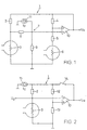
- the device according to FIG. 1 comprises a Wheatstone bridge 1 with a first branch, the first one in series Bridge resistance 2 and in the vessel to be monitored first resistance element 3, preferably a measuring wire contains.
- first resistance element 3 preferably a measuring wire contains.
- second bridge resistor 4 and a series resistor 5 with a second, in the same vessel, preferably close to that first resistance element 3 arranged second Resistor element 6, also a measuring wire, in series.
- first bridge resistor 2 and the first resistance element 3 there is a tap which is connected to the inverting input of an operational amplifier 10 via a voltage divider 7 consisting of high-resistance resistors 8, 9, while a second tap is connected between the second bridge resistor 4 and the series resistor 5 is connected to its non-inverting input.
- the output of the operational amplifier 10 feeds the Wheatstone bridge 1 and at the same time supplies the output voltage U a .
- a constant current source 11 is connected, which feeds a constant current I 0 .
- the resistance R P1 of the first resistance element 3 and the resistance R P2 of the second resistance element 6 each have a positive temperature coefficient.
- the Wheatstone bridge 1 is kept in the balanced state by the operational amplifier 10.
- the following applies if the values of the first bridge resistor 2 and the second bridge resistor 4 are denoted by R G1 , R G2 , that of the series resistor 5 by R v and the division factor of the voltage divider 7 by k and the constant current I 0 is initially ignored: (2) k ⁇ R P1 / (R P1 + R G1 ) (R V + R P2 ) / (R G2 + R V + R P2 )
- the resistors can now be dimensioned such that for a certain pressure, which is preferably in the upper part of the measuring range and for an average wall temperature, the derivative of the left term in (2) after the temperature T 1 of the first resistance element 3 follows that of the right term corresponds to the temperature T 2 of the second resistance element 6. Since the temperatures T 1 , T 2 of the first resistance element 3 and of the second resistance element 6 change in the same way when the wall temperature T w changes, the equality of the terms remains essentially unchanged. By feeding the constant current I 0 , the left term is shifted slightly, so that both terms match at the same temperature changes at two points and are very close to each other in between. A readjustment of the Wheatstone bridge 1 therefore largely does not occur with the same changes in the temperatures T 1 , T 2 of the resistance elements 3, 6 in the range mentioned, ie the output voltage U a practically does not change when the wall temperature T w changes.
- the resistance elements 3, 6 can each have a cold resistance of 87 ⁇ .
- the resistors 8, 9 of the voltage divider 7 are, as mentioned above, high-impedance, so that they have virtually no influence on the current through the Wheatstone bridge 1. You can e.g. B. 82.2 k ⁇ and 100 k ⁇ can be selected.
- the constant current I 0 can be, for example, 1 ⁇ A.
- the two branches of the Wheatstone bridge 1 are in any case set such that a relatively high current flows through the branch containing the first resistance element 3 and a significantly lower current flows through the branch containing the second resistance element 6.
- the resistance elements 3 and 6 therefore also have different temperatures T 1 , T 2 .
- the temperature changes in the resistors R P1 , R P2 of the resistance elements caused by changes in the pressure and the resulting heat loss are therefore also different and lead to a readjustment of the Wheatstone bridge 1 by the operational amplifier 10, which also results in a change in the output voltage U a precipitates.
- the output signal is essentially evaluated after a recorded calibration curve, since the purely arithmetical Evaluation because of the relatively complicated structure the device would only be possible with greater effort. It can also on the same resistance element of the Resistance at different temperatures are recorded by the temperature z. B. by periodic switching a resistance of one containing the resistance element Wheatstone Bridge is being converted.
- the Wheatstone bridge 1 also comprises a Wheatstone bridge 1 with a first branch, which contains in series a first bridge resistor 2 and a resistance element 3 arranged in the vessel, preferably designed as a measuring wire, and a second branch with a series connection of two basic resistors 12, 13.
- the Wheatstone bridge 1 is in turn balanced by an operational amplifier 10, specifically via a switch 14, for. B. a transistor.
- a constant current source 15 feeds a constant current I 0 into the Wheatstone bridge 1.
- the bridge resistance 2 can have a value of 100 ⁇ , for example, the basic resistances 12, 13 those of 10 k ⁇ or 14 k ⁇ , while the cold resistance of the resistance element 3 is 87 ⁇ .
- the constant current I 0 can be 100 ⁇ A.
- the Wheatstone bridge 1 is adjusted by the operational amplifier 10. After thermal stabilization of the circuit results from the output voltage U a and the constant resistance values in a known manner, the resistance R P on the resistance element 3 and from the known relationship between temperature and resistance R P also the temperature T 1 of the resistance element 3, and the voltage drop the same and thus the pressure-dependent power N (p) emitted by it through radiation and heat conduction, although according to (1) the not exactly known wall temperature T w influences this variable.
- the adjustment of the Wheatstone bridge 1 is now suspended.
- the final value can possibly be determined beforehand from the course of the transient process - a part of the constant current I 0 flows through the resistance element 3, which is preferably dimensioned such that it does not heat it up appreciably.
- the resistance of the resistance element 3 can again be determined and its temperature T 2 can be determined, which now corresponds to the wall temperature T W. After inserting this value in (1), the equation can be solved for p.
- the device according to FIG. 3 in turn comprises a Wheatstone bridge 1 with a bridge resistance 2 of z. B. 100 ⁇ and one connected in series with the same, in Vessel-arranged resistance element 3, preferably one Measuring wire with a cold resistance of 87 ⁇ in a first Branch and two basic resistors 12, 13 of z. B. 10 k ⁇ and 14 k ⁇ in a second branch, which of a Operational amplifier 10 is adjusted.
- Second Basic resistor 13 can be a parallel resistor 13 'from for example 120 k ⁇ by means of a switch 16 can be connected in parallel.
- an amplifier 17 which is connected via a coupling resistor 18 of z. B. 1 M ⁇ is fed back to its non-inverting input and an amplitude controller 19 is connected in parallel.
- the output voltage U a is fed to a frequency measuring device 20, which forwards its measurement result to a microprocessor 21.
- the microprocessor 21 also operates the switch 16.
- a transient is triggered, in which the resistance element 3 adjusts to a temperature T 1 .
- the feedback of the Wheatstone bridge 1, controlled by the amplitude controller 19, via the amplifier 17 stabilizes the oscillation about the rest position corresponding to a complete adjustment, the amplifier 17 being controlled in such a way that the amplitude of the oscillation assumes a fixed, relatively small value.
- the frequency ⁇ 1 of this oscillation which depends on the gas pressure p via the thermal conductivity and the thermal capacity of the gas and also on the wall temperature T W , is recorded by the frequency measuring device 20 and passed on to the microprocessor 21.
- the switch 16 which causes a change in the division ratio and a readjustment of the Wheatstone bridge 1 by setting the resistance element 3 to a lower resistance and thus a lower temperature T. 2 entails.
- An oscillation also arises around this rest position, the frequency ⁇ 2 of which is detected by the frequency measuring device 20 after the device has stabilized and in turn depends on the thermal conductivity and the thermal capacity of the gas on its pressure p and also on the wall temperature T W.
- T W the dimensions given above give frequencies of the order of 50 Hz at 10 -3 mbar and 2 kHz at 1 bar.
- each point corresponds to a pressure-temperature pair (p, T W ).
- the values of ⁇ 1 , ⁇ 2 corresponding to certain pressures and wall temperatures can be determined by calibration measurements and stored in a table in a memory.
- the microprocessor 21 can determine the pressure p and the wall temperature T W from a frequency pair ( ⁇ 1 , ⁇ 2 ) by interpolation from the closest stored values.
- lines of constant wall temperature T W and lines of constant gas pressure p are given.
- the gas pressure p is determined on the basis of electrical quantities that occur in succession on one and the same resistance element 3.
Landscapes
- Physics & Mathematics (AREA)
- General Physics & Mathematics (AREA)
- Measuring Fluid Pressure (AREA)
Claims (11)
- Procédé de mesure de la pression d'un gaz (p) dans un récipient, à l'aide d'au moins un élément résistif (3, 6) traversé par un courant électrique, qui est placé, par l'intermédiaire du gaz, en contact de conductivité thermique avec la paroi du récipient, caractérisé en ce que, pour au moins deux températures de mesure (T1, T2) différentes, chaque fois sur un élément résistif (3, 6) sont appréhendées des grandeurs électriques et la pression de gaz (p) est déterminée sur la base de celles-ci.
- Procédé selon la revendication 1, caractérisé en ce que la détection des grandeurs électriques s'effectue l'une après l'autre sur un élément résistif (3) unique.
- Procédé selon la revendication 1, caractérisé en ce que deux éléments résistifs (3, 6) sont réglés à des températures (T1, T2) différentes et des variations de température identiques de ceux-ci sont compensées.
- Procédé selon la revendication 1 ou 2, caractérisé en ce qu'au moins un élément résistif (3) est exposé, au moins périodiquement, à un courant constant (I0) connu et, à partir de la chute de tension (U0) au passage de l'élément résistif (3), la valeur de sa résistance et, à partir de là, la température de paroi (Tw) sont déterminées.
- Procédé selon la revendication 1 ou 2, caractérisé en ce que le au moins un élément résistif (3) fait partie, pour chacune des températures de mesure (T1, T2), d'un système susceptible d'entrer en oscillation, dont la fréquence (ν1, ν2) dépend de la pression de gaz (p) et de la température de paroi (Tw) et est chaque fois déterminée.
- Dispositif de mise en oeuvre du procédé selon la revendication 3, avec un pont de Wheatstone (1) équilibré par un amplificateur opérationnel (10), pont dans la première branche duquel est situé un élément résistif (3), caractérisé en ce que, dans la deuxième branche de pont de Wheatstone (1), est également placé un élément résistif (6) et que celle-ci est accordée de manière que, en au moins un point de la plage de mesure, les fonctions linéarisées des tensions, prélevées sur le pont de Wheatstone (1) dans le but de l'équilibrage, dont la variable est la température de mesure (T1; T2) de l'élément résistif (3; 6), sont identiques dans chaque branche.
- Dispositif selon la revendication 6, caractérisé en ce que le point de prélèvement, situé entre une première résistance de pont (2) et le premier élément résistif (3), sur le pont de Wheatstone (1) est relié à l'amplificateur opérationnel (10) par un diviseur de tension (7) et une résistance série (5) est branchée directement en amont du deuxième élément résistif (6).
- Dispositif selon la revendication 7, caractérisé en ce que la sortie du diviseur de tension (7) est reliée à une source de courant constant (11).
- Dispositif de mise en oeuvre du procédé selon la revendication 4, avec un pont de Wheatstone (1) susceptible d'être équilibré par un amplificateur opérationnel (10), pont dans la branche duquel est placé un élément résistif (3), caractérisé en ce que la sortie de l'amplificateur opérationnel (10) est retournée, par un élément de commutation (14), au pont de Wheatstone (1) et celui-ci est relié à une source de courant constant (15).
- Dispositif de mise en oeuvre du procédé selon la revendication 5, avec un pont de Wheatstone (1), équilibré par un amplificateur opérationnel (10), pont dans la première branche duquel est placé un élément résistif (3), caractérisé en ce que l'amplificateur opérationnel (10) est muni d'une rétroaction par l'intermédiaire d'un amplificateur (17), réglé par un régulateur d'amplitude (19).
- Dispositif selon la revendication 10, caractérisé en ce qu'au moins une valeur de résistance est susceptible d'être commutée dans l'une des branches du pont de Wheatstone (1), dans le but de modifier son rapport de division.
Applications Claiming Priority (3)
| Application Number | Priority Date | Filing Date | Title |
|---|---|---|---|
| CH02216/97A CH692762A5 (de) | 1997-09-22 | 1997-09-22 | Verfahren zur Messung des Gasdrucks in einem Gefäss sowie Vorrichtungen zur Durchführung des Verfahrens. |
| CH221697 | 1997-09-22 | ||
| PCT/CH1998/000375 WO1999015869A1 (fr) | 1997-09-22 | 1998-09-01 | Procede pour mesurer la pression du gaz dans un recipient, et dispositifs pour sa mise en oeuvre |
Publications (2)
| Publication Number | Publication Date |
|---|---|
| EP1017976A1 EP1017976A1 (fr) | 2000-07-12 |
| EP1017976B1 true EP1017976B1 (fr) | 2001-11-21 |
Family
ID=4228575
Family Applications (1)
| Application Number | Title | Priority Date | Filing Date |
|---|---|---|---|
| EP98939464A Expired - Lifetime EP1017976B1 (fr) | 1997-09-22 | 1998-09-01 | Procede pour mesurer la pression du gaz dans un recipient, et dispositifs pour sa mise en oeuvre |
Country Status (7)
| Country | Link |
|---|---|
| US (1) | US6474172B1 (fr) |
| EP (1) | EP1017976B1 (fr) |
| JP (1) | JP4332296B2 (fr) |
| CH (1) | CH692762A5 (fr) |
| DE (1) | DE59802761D1 (fr) |
| DK (1) | DK1017976T3 (fr) |
| WO (1) | WO1999015869A1 (fr) |
Cited By (1)
| Publication number | Priority date | Publication date | Assignee | Title |
|---|---|---|---|---|
| DE102013219437A1 (de) * | 2013-09-26 | 2015-03-26 | Robert Bosch Gmbh | Verfahren und Vorrichtung zum Bewerten einer Güte eines Vakuums |
Families Citing this family (13)
| Publication number | Priority date | Publication date | Assignee | Title |
|---|---|---|---|---|
| US6658941B1 (en) | 1997-07-21 | 2003-12-09 | Helix Technology Corporation | Apparatus and methods for heat loss pressure measurement |
| US6938493B2 (en) * | 1997-07-21 | 2005-09-06 | Helix Technology Corporation | Apparatus and methods for heat loss pressure measurement |
| US20060021444A1 (en) * | 2004-07-28 | 2006-02-02 | Helix Technology Corporation | Method of operating a resistive heat-loss pressure sensor |
| WO2006020196A1 (fr) | 2004-07-28 | 2006-02-23 | Brooks Automation, Inc. | Procedez de fonctionnement d'un capteur de pression a perte d'energie et a resistance |
| US7249516B2 (en) * | 2004-07-28 | 2007-07-31 | Brooks Automation, Inc. | Method of operating a resistive heat-loss pressure sensor |
| US20060188934A1 (en) * | 2005-02-22 | 2006-08-24 | Ying-Lan Chang | System and method for implementing a high-sensitivity sensor with improved stability |
| US7331237B2 (en) * | 2006-02-01 | 2008-02-19 | Brooks Automation, Inc. | Technique for improving Pirani gauge temperature compensation over its full pressure range |
| JP4831670B2 (ja) * | 2006-02-24 | 2011-12-07 | 富士通株式会社 | 試料抵抗測定装置 |
| DE102007053944A1 (de) | 2007-11-09 | 2009-05-20 | Vacuubrand Gmbh + Co Kg | Wärmeleitungs-Gasdruckmeßanordnung |
| KR101460158B1 (ko) * | 2008-11-20 | 2014-11-10 | 삼성전자주식회사 | 온도 변화에 강인한 휘스톤 브리지 최적화 장치 및 방법 |
| US8171801B2 (en) * | 2008-12-19 | 2012-05-08 | Institut National D'optique | Micro-thermistor gas pressure sensor |
| CN111289173A (zh) * | 2020-03-11 | 2020-06-16 | 无锡物联网创新中心有限公司 | 一种皮拉尼真空计系统 |
| DE102024108521B4 (de) * | 2024-03-26 | 2026-01-08 | Vacom Vakuum Komponenten & Messtechnik Gmbh | Verfahren zum Betreiben eines Pirani-Drucksensors und Vorrichtung |
Family Cites Families (8)
| Publication number | Priority date | Publication date | Assignee | Title |
|---|---|---|---|---|
| DE1029599B (de) * | 1953-11-27 | 1958-05-08 | Heraeus Gmbh W C | Heissleitervakuummeter |
| US3066537A (en) * | 1958-07-24 | 1962-12-04 | New York Air Brake Co | Pressure gauge |
| DE1947211A1 (de) * | 1969-09-18 | 1971-05-06 | Licentia Gmbh | Druckmesseinrichtung |
| GB2105047B (en) * | 1981-08-28 | 1986-04-03 | British Oxygen Co Ltd | Pirani gauges |
| DE3230405A1 (de) * | 1981-08-28 | 1983-03-10 | Boc Ltd., London | Gasdruck-messschaltung |
| DE4308434A1 (de) * | 1993-03-17 | 1994-09-22 | Leybold Ag | Temperaturkompensation bei einem geregelten Wärmeleitungsvakuummeter |
| DE4308433A1 (de) * | 1993-03-17 | 1994-09-22 | Leybold Ag | Wärmeleitungsvakuummeter mit Meßzelle, Meßgerät und Verbindungskabel |
| US5962791A (en) * | 1998-07-16 | 1999-10-05 | Balzers Aktiengellschaft | Pirani+capacitive sensor |
-
1997
- 1997-09-22 CH CH02216/97A patent/CH692762A5/de not_active IP Right Cessation
-
1998
- 1998-09-01 DK DK98939464T patent/DK1017976T3/da active
- 1998-09-01 WO PCT/CH1998/000375 patent/WO1999015869A1/fr not_active Ceased
- 1998-09-01 JP JP2000513120A patent/JP4332296B2/ja not_active Expired - Fee Related
- 1998-09-01 EP EP98939464A patent/EP1017976B1/fr not_active Expired - Lifetime
- 1998-09-01 DE DE59802761T patent/DE59802761D1/de not_active Expired - Lifetime
- 1998-09-01 US US09/508,605 patent/US6474172B1/en not_active Expired - Fee Related
Cited By (2)
| Publication number | Priority date | Publication date | Assignee | Title |
|---|---|---|---|---|
| DE102013219437A1 (de) * | 2013-09-26 | 2015-03-26 | Robert Bosch Gmbh | Verfahren und Vorrichtung zum Bewerten einer Güte eines Vakuums |
| DE102013219437B4 (de) * | 2013-09-26 | 2015-12-10 | Robert Bosch Gmbh | Verfahren und Vorrichtung zum Bewerten einer Güte eines Vakuums |
Also Published As
| Publication number | Publication date |
|---|---|
| DE59802761D1 (de) | 2002-02-21 |
| JP4332296B2 (ja) | 2009-09-16 |
| WO1999015869A1 (fr) | 1999-04-01 |
| DK1017976T3 (da) | 2002-05-21 |
| CH692762A5 (de) | 2002-10-15 |
| JP2001517784A (ja) | 2001-10-09 |
| US6474172B1 (en) | 2002-11-05 |
| EP1017976A1 (fr) | 2000-07-12 |
Similar Documents
| Publication | Publication Date | Title |
|---|---|---|
| DE69015838T2 (de) | Verfahren und Vorrichtung zur Messung der Wärmeleitfähigkeit von Gasen. | |
| DE2917237C2 (fr) | ||
| DE2900382A1 (de) | Spannungsmesser-druckwandlergeraet | |
| EP1017976A1 (fr) | Procede pour mesurer la pression du gaz dans un recipient, et dispositifs pour sa mise en oeuvre | |
| EP0373414A1 (fr) | Méthode et dispositif pour la mesure des paramètres fluidiques ou calorimétriques | |
| DE3115776A1 (de) | Thermoelektrische fuellstandsmesseinrichtung | |
| DE3877518T2 (de) | Detektor fuer brennbare gase mit temperaturstabilisierung. | |
| DE2615139C3 (de) | Verfahren zum Bestimmen eines Magnetfeldes und Anordnung zur Durchführung des Verfahrens | |
| DE69026454T2 (de) | Kompensationsschaltung für Nullpunktabweichung | |
| EP0101956A2 (fr) | Thermomètre à résistance | |
| EP0689670B1 (fr) | Vacuometre a conductibilite thermique avec cellule de mesure, appareil de mesure et cable de connexion | |
| DE1914596A1 (de) | Vorrichtung zur Messung durch Ermittlung der Temperatur eines durch Joule-Effekt geheizten Heizfadens | |
| DE19909469C1 (de) | Vorrichtung und Verfahren zur Messung der Strömungsgeschwindigkeit eines Fluids | |
| DE2524997C3 (de) | Schaltung zum Messen des Effektivwertes eines elektrischen Signals | |
| DE1698249B2 (de) | Schaltung zur kompensation der grundlinienneigung des thermogramms bei zwei gegenpolig in reihe geschalteten thermoelementen eines differential-thermoanalysators | |
| DE2944364C2 (de) | Anordnung zur Messung einer Größe, die einen Feldeffekttransistor beeinflußt | |
| DE2353812C3 (de) | Temperaturmeßschaltung | |
| EP0667509A2 (fr) | Compensation de température pour capteurs du débit massique selon le principe d'anémomètres à fil chaud | |
| DE2519758C2 (de) | Einrichtung zur temperatur-fernmessung | |
| EP0333916A2 (fr) | Procédé de régulation de température de conducteurs chauffants résistifs | |
| DE2839617C2 (de) | Meßanordnung | |
| DE3149990C2 (fr) | ||
| DE3024328A1 (de) | Einrichtung zur messung einer physikalischen groesse | |
| DE2249102C3 (de) | Verfahren und Vorrichtung zur Bestimmung der Materialablagerung auf der Oberfläche einer Sonde | |
| DE550106C (de) | Einrichtung zur Fernmessung von in Abhaengigkeit von Messgroessen sich einstellenden Widerstaenden |
Legal Events
| Date | Code | Title | Description |
|---|---|---|---|
| PUAI | Public reference made under article 153(3) epc to a published international application that has entered the european phase |
Free format text: ORIGINAL CODE: 0009012 |
|
| 17P | Request for examination filed |
Effective date: 20000310 |
|
| AK | Designated contracting states |
Kind code of ref document: A1 Designated state(s): DE DK FR GB IT |
|
| RAP1 | Party data changed (applicant data changed or rights of an application transferred) |
Owner name: UNAXIS BALZERS AKTIENGESELLSCHAFT |
|
| GRAG | Despatch of communication of intention to grant |
Free format text: ORIGINAL CODE: EPIDOS AGRA |
|
| 17Q | First examination report despatched |
Effective date: 20010405 |
|
| GRAG | Despatch of communication of intention to grant |
Free format text: ORIGINAL CODE: EPIDOS AGRA |
|
| GRAH | Despatch of communication of intention to grant a patent |
Free format text: ORIGINAL CODE: EPIDOS IGRA |
|
| GRAH | Despatch of communication of intention to grant a patent |
Free format text: ORIGINAL CODE: EPIDOS IGRA |
|
| GRAA | (expected) grant |
Free format text: ORIGINAL CODE: 0009210 |
|
| AK | Designated contracting states |
Kind code of ref document: B1 Designated state(s): DE DK FR GB IT |
|
| REG | Reference to a national code |
Ref country code: GB Ref legal event code: IF02 |
|
| GBT | Gb: translation of ep patent filed (gb section 77(6)(a)/1977) |
Effective date: 20020122 |
|
| REF | Corresponds to: |
Ref document number: 59802761 Country of ref document: DE Date of ref document: 20020221 |
|
| REG | Reference to a national code |
Ref country code: DK Ref legal event code: T3 |
|
| PLBE | No opposition filed within time limit |
Free format text: ORIGINAL CODE: 0009261 |
|
| STAA | Information on the status of an ep patent application or granted ep patent |
Free format text: STATUS: NO OPPOSITION FILED WITHIN TIME LIMIT |
|
| 26N | No opposition filed | ||
| PGFP | Annual fee paid to national office [announced via postgrant information from national office to epo] |
Ref country code: DK Payment date: 20030915 Year of fee payment: 6 |
|
| PG25 | Lapsed in a contracting state [announced via postgrant information from national office to epo] |
Ref country code: DK Free format text: LAPSE BECAUSE OF NON-PAYMENT OF DUE FEES Effective date: 20040930 |
|
| REG | Reference to a national code |
Ref country code: DK Ref legal event code: EBP |
|
| PG25 | Lapsed in a contracting state [announced via postgrant information from national office to epo] |
Ref country code: IT Free format text: LAPSE BECAUSE OF NON-PAYMENT OF DUE FEES;WARNING: LAPSES OF ITALIAN PATENTS WITH EFFECTIVE DATE BEFORE 2007 MAY HAVE OCCURRED AT ANY TIME BEFORE 2007. THE CORRECT EFFECTIVE DATE MAY BE DIFFERENT FROM THE ONE RECORDED. Effective date: 20050901 |
|
| PGFP | Annual fee paid to national office [announced via postgrant information from national office to epo] |
Ref country code: FR Payment date: 20130910 Year of fee payment: 16 Ref country code: GB Payment date: 20130828 Year of fee payment: 16 |
|
| GBPC | Gb: european patent ceased through non-payment of renewal fee |
Effective date: 20140901 |
|
| REG | Reference to a national code |
Ref country code: FR Ref legal event code: ST Effective date: 20150529 |
|
| PG25 | Lapsed in a contracting state [announced via postgrant information from national office to epo] |
Ref country code: GB Free format text: LAPSE BECAUSE OF NON-PAYMENT OF DUE FEES Effective date: 20140901 |
|
| PG25 | Lapsed in a contracting state [announced via postgrant information from national office to epo] |
Ref country code: FR Free format text: LAPSE BECAUSE OF NON-PAYMENT OF DUE FEES Effective date: 20140930 |
|
| PGFP | Annual fee paid to national office [announced via postgrant information from national office to epo] |
Ref country code: DE Payment date: 20150825 Year of fee payment: 18 |
|
| REG | Reference to a national code |
Ref country code: DE Ref legal event code: R119 Ref document number: 59802761 Country of ref document: DE |
|
| PG25 | Lapsed in a contracting state [announced via postgrant information from national office to epo] |
Ref country code: DE Free format text: LAPSE BECAUSE OF NON-PAYMENT OF DUE FEES Effective date: 20170401 |