EP1018330A2 - Maschine zum Dosieren von flüssigen pharmazeutischen Produkten - Google Patents
Maschine zum Dosieren von flüssigen pharmazeutischen Produkten Download PDFInfo
- Publication number
- EP1018330A2 EP1018330A2 EP99125943A EP99125943A EP1018330A2 EP 1018330 A2 EP1018330 A2 EP 1018330A2 EP 99125943 A EP99125943 A EP 99125943A EP 99125943 A EP99125943 A EP 99125943A EP 1018330 A2 EP1018330 A2 EP 1018330A2
- Authority
- EP
- European Patent Office
- Prior art keywords
- hole
- valve
- machine
- along
- channel
- Prior art date
- Legal status (The legal status is an assumption and is not a legal conclusion. Google has not performed a legal analysis and makes no representation as to the accuracy of the status listed.)
- Withdrawn
Links
- 239000007788 liquid Substances 0.000 title claims abstract description 50
- 239000000825 pharmaceutical preparation Substances 0.000 title claims abstract description 12
- 229940127557 pharmaceutical product Drugs 0.000 title claims abstract description 12
- 239000002775 capsule Substances 0.000 description 20
- 239000002245 particle Substances 0.000 description 2
- 239000000047 product Substances 0.000 description 2
- 239000000725 suspension Substances 0.000 description 2
- 241000237983 Trochidae Species 0.000 description 1
- 230000005465 channeling Effects 0.000 description 1
- 238000002347 injection Methods 0.000 description 1
- 239000007924 injection Substances 0.000 description 1
- 239000012263 liquid product Substances 0.000 description 1
- 238000004806 packaging method and process Methods 0.000 description 1
- 230000002093 peripheral effect Effects 0.000 description 1
- 230000009974 thixotropic effect Effects 0.000 description 1
Images


Classifications
-
- A—HUMAN NECESSITIES
- A61—MEDICAL OR VETERINARY SCIENCE; HYGIENE
- A61J—CONTAINERS SPECIALLY ADAPTED FOR MEDICAL OR PHARMACEUTICAL PURPOSES; DEVICES OR METHODS SPECIALLY ADAPTED FOR BRINGING PHARMACEUTICAL PRODUCTS INTO PARTICULAR PHYSICAL OR ADMINISTERING FORMS; DEVICES FOR ADMINISTERING FOOD OR MEDICINES ORALLY; BABY COMFORTERS; DEVICES FOR RECEIVING SPITTLE
- A61J3/00—Devices or methods specially adapted for bringing pharmaceutical products into particular physical or administering forms
- A61J3/07—Devices or methods specially adapted for bringing pharmaceutical products into particular physical or administering forms into the form of capsules or similar small containers for oral use
- A61J3/071—Devices or methods specially adapted for bringing pharmaceutical products into particular physical or administering forms into the form of capsules or similar small containers for oral use into the form of telescopically engaged two-piece capsules
- A61J3/074—Filling capsules; Related operations
-
- B—PERFORMING OPERATIONS; TRANSPORTING
- B65—CONVEYING; PACKING; STORING; HANDLING THIN OR FILAMENTARY MATERIAL
- B65B—MACHINES, APPARATUS OR DEVICES FOR, OR METHODS OF, PACKAGING ARTICLES OR MATERIALS; UNPACKING
- B65B3/00—Packaging plastic material, semiliquids, liquids or mixed solids and liquids, in individual containers or receptacles, e.g. bags, sacks, boxes, cartons, cans, or jars
- B65B3/26—Methods or devices for controlling the quantity of the material fed or filled
- B65B3/30—Methods or devices for controlling the quantity of the material fed or filled by volumetric measurement
- B65B3/32—Methods or devices for controlling the quantity of the material fed or filled by volumetric measurement by pistons co-operating with measuring chambers
- B65B3/323—Methods or devices for controlling the quantity of the material fed or filled by volumetric measurement by pistons co-operating with measuring chambers with measuring chambers travelling in an endless path
Definitions
- the present invention relates to a machine for metering liquid pharmaceutical products into capsules or phials.
- reciprocating machines substantially comprise a first body operating in steps and supporting a number of capsules in a spoke arrangement; a second body with internal channels and which rotates between two positions; a hopper full of liquid; and a number of hydraulic pistons.
- the second body in a first position, connects the hopper hydraulically to the pistons into which a predetermined quantity of liquid is drawn, and, in a second position, connects the pistons hydraulically to respective capsules, which are arrested, for a predetermined time beneath the second body, pending injection of the liquid by the pistons into the capsules.
- a continuously operating machine as described in European Patent Application nr 91105443.5 filed on 5 April 1991, and which comprises a rotary vessel full of liquid; a body having a number of hydraulic pistons; and a number of valves for channeling the liquid from the vessel to the pistons, and from the pistons to the capsules.
- the valves are slide types and are movable, along respective longitudinal axes, between a first position hydraulically connecting the vessel to the pistons, and a second position hydraulically connecting each piston to a corresponding capsule.
- a machine for metering liquid pharmaceutical products into bottom shells comprising:
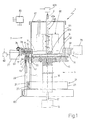
- Number 1 in Figure 1 indicates as a whole a machine for metering liquid pharmaceutical products into capsules, and more specifically into bottom shells 2 of the capsules.
- liquid products is intended to mean liquids proper, thixotropic liquids, heat-melt liquids (inserted in the form of paste or very dense liquids) and liquids with particles in suspension.
- Machine 1 may be divided schematically along its vertical longitudinal axis X into three substantially cylindrical rotary parts 3, 4, 5 coaxial and angularly integral with one another.
- the top part, indicated 3 comprises a cylindrical vessel 6 supplied with liquid from a known hopper (not shown) at the top;
- the central part, indicated 4 comprises a number of valves 8 which rotate, about respective horizontal longitudinal axes Y, between a first position in which a predetermined quantity of liquid is drawn from vessel 6, and a second position in which said quantity is channeled into a bottom shell 2 of a capsule;
- the bottom part, indicated 5, comprises a number of hydraulic pistons 11, one for each valve 8, for providing the thrust by which to channel the liquid into bottom shell 2.
- Bottom part 5 also comprises a cylindrical, externally toothed portion 12 which rotates about axis X and with which meshes a belt 13 having a number of bushes 14 engaged by respective bottom shells 2.
- Machine 1 normally forms part of a system comprising a number of known machines for performing various functions, such as a machine for supplying the capsules; a machine for orienting the capsules and separating the top shells from bottom shells 2; other machines for metering pharmaceutical products of various types and/or in other possible forms; a machine for closing the capsules; and a capsule packaging machine. All these machines are normally powered by the same drive means, e.g. belts, pulleys, or mesh directly with one another, have respective toothed portions similar to portion 12 and with which belt 13 meshes, and are substantially tangent to one another so that belt 13 travels along the whole system.
- drive means e.g. belts, pulleys, or mesh directly with one another, have respective toothed portions similar to portion 12 and with which belt 13 meshes, and are substantially tangent to one another so that belt 13 travels along the whole system.
- Bottom part 5 is rotated about axis X by a shaft 16 coaxial with axis X and connected to the output shaft 17 of a motor 18 in known manner, as stated, on machines of this sort and therefore shown only schematically.
- Portion 12 is in the form of a rotary drum having, along an intermediate ring, a number of equally spaced vertical through holes 22, along each of which a respective piston 11, associated with each valve 8, slides in reciprocating manner.
- Machine 1 also comprises a device 21 for controlling translation of pistons 11, and which comprises a fixed cylindrical cam 23 in which is formed an annular track 24 engaged by a wheel 25 carried by a bottom end portion of each piston 11.
- the above translation control system is only shown schematically, by being known and also used on other machines of this sort, though normally for translating pins performing different functions from those of pistons 11.
- central part 4 comprises a cup-shaped body 31 carried by portion 12 and in turn comprising a circular bottom wall 32 and an annular lateral wall 33 extending upwards from the peripheral edge of wall 32.
- Wall 33 is low in height, is decidedly thicker than wall 32, and has a number of equally spaced radial through holes 34, each housing a corresponding valve 8.
- Each hole 34 also houses a cylindrical sleeve 35 integral with wall 33; the end, inside machine 1, of sleeve 35 is substantially flush with the end, inside machine 1, of hole 34; sleeve 35 has two vertical through holes 36, 37, each for connecting the inside of hole 34 to a respective vertical through hole 38, 41 formed close to the rim of bottom wall 32; hole 38 is coaxial with bottom shell 2 underneath; and hole 41 is coaxial with a corresponding hole 22 underneath.
- machine 1 comprises, for each piston 11, a cylindrical bush 42 inside which piston 11 translates, and which comprises a bottom portion 43 housed inside hole 22, and a top portion 44 housed inside hole 41.
- Machine 1 also comprises, for each hole 38, a further bush 45 in turn comprising a top portion 46 housed inside hole 36, a central portion 47 housed inside hole 38, and a bottom portion 48 outside hole 38 and beneath wall 32.
- Each bush 45 is fitted inside with an on-off valve 51 comprising a ball 53, and a spring 54 for pushing ball 53 upwards and against a shoulder formed along the inner hole of bush 45.
- each bush 14 is associated with a vertical pin 59 movable axially, by means of a device 60 similar to device 21, between a first position in which the top tip of pin 59 is outside bush 14, and a second position, assumed when metering the liquid into bottom shell 2, in which the top tip of pin 59 penetrates bush 14 to move bottom shell 2 up to bush 45.
- each valve 8 comprises a substantially cylindrical valve body 61 having and free to rotate about a longitudinal axis Y, and in turn comprising a portion 62 housed inside sleeve 35, and a portion 63 outside sleeve 35 and hole 34.
- Annular seals 69 are fitted between sleeve 35 and the inside of hole 34, and between portion 62 and the inside of sleeve 35; the end, inside machine 1, of portion 62 is substantially flush with the end, inside machine 1, of sleeve 35; and portion 62 comprises a first channel, which, in a first angular position of valve 8, hydraulically connects the inside of vessel 6 to the inside of bush 42, and a second channel, separate from the first, which, in a second angular position of valve 8, hydraulically connects the inside of bush 42 to the inside of bush 45.
- vessel 6 is defined at the bottom by the upper face of wall 32, and laterally by the inner face of wall 33 and by the inner face of a tall, thin, hollow cylinder 64 integral with wall 33 and extending upwards, coaxially with axis X, from the upper face of wall 33.
- Vessel 6 is fitted inside with a known mixing device 65 and a known heat exchanger 66;
- cylinder 64 is closed at the top by a fixed cover 67 supporting devices 65 and 66;
- device 65 comprises a rotary shaft 65a of axis X, drive means 65b for driving shaft 65a, and an appendix 65c extending from the bottom end portion of shaft 65a and for mixing the liquid inside vessel 6.
- the first channel of portion 62 is defined by a slot 68 formed, along a horizontal axis parallel to axis Y, on the outer face of portion 62, at the end of portion 62 inside machine 1, and which is of such a length as to face hole 37 in a given angular position of portion 62. That is, in said given angular position of portion 62, slot 68 hydraulically connects the inside of vessel 6 to the inside of hole 37 and, via hole 37 and hole 41, to the inside of bush 42.
- the second channel is defined by a dead hole 71 formed along axis Y, and by two holes 72 and 73 extending radially from hole 71; the axis of hole 72 lies in the same plane as the axis of hole 36; the axis of hole 73 lies in the same plane as the axis of hole 37; hole 71 extends from portion 63 up to a portion of portion 62 corresponding to the inner end of slot 68; at portion 63 and an adjacent portion of portion 62, hole 71 is closed by a plug 74, so that the second channel is longitudinally U-shaped; and, in a given angular position of portion 62, the second channel hydraulically connects holes 37 and 36 to each other, and therefore the inside of bush 42 to the inside of bush 45.
- portion 63 of valve body 61 supports a pin 75 extending from the vertical face, outside machine 1, of portion 63, and fitted with an idle wheel 76.
- Machine 1 ( Figure 1) comprises two fixed cams 77 and 78, which cooperate with wheel 76 to rotate valve body 61, about respective axis Y, between a first position permitting withdrawal from vessel 6 of a predetermined quantity of liquid stored inside bush 42, and a second position enabling said quantity to be channeled into a bottom shell 2 of a capsule, and vice versa.
- Cams 77 and 78 are defined by respective wedges fitted outside machine 1 at a given angular distance from each other; and the wedges have respective faces on which wheel 76 rests, and which extend in an oblique plane with respect to the horizontal plane of axes Y of valves 8.
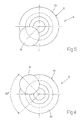
- valve 8 As of the angular position of valve 8 shown in Figures 2 and 5, wheel 76, as parts 3, 4 and 5 rotate, comes into contact with cam 77 so as to rotate valve 8 (90° in the embodiment shown) from said first angular position to said second angular position.
- wheel 76 is detached from cam 77, valve 8 remains in said second position until wheel 76 - again, as parts 3, 4 and 5 rotate - comes into contact with cam 78 so as to rotate valve 8 (again by 90°) from said second angular position to said first angular position.
- machine 1 also comprises a sensor 81 for detecting the presence of bottom shells 2 inside respective bushes 14 on belt 13; and means 82 for moving cam 77 between a work position, in which, for each turn of rotary parts 3, 4 and 5, cam 77 comes into contact with wheels 76 of valves 8, and an extracted position in which cam 77 is moved clear of and not contacted by wheel 76.
- the operation of machine 1 is controlled by an electronic central control unit 83.
- wheel 76 comes into contact with cam 77 to rotate portion 62 of valve 8 into such an angular position as to hydraulically connect chamber 42a to bush 45 for a predetermined length of time, and to hydraulically disconnect vessel 6 and chamber 42a for the same length of time.
- a bottom shell 2 is positioned coaxially beneath bush 45, ready to receive a predetermined quantity of liquid, and the corresponding piston 11 is raised to expel the liquid from chamber 42a; which liquid, via the second channel formed in portion 62, is forced into bush 45 and from bush 45 into bottom shell 2, by the pressure exerted by piston 11 overcoming the action of spring 54 and so freeing the flow passage along bush 45.
- the quantity of liquid fed into bottom shell 2 is directly proportional to the travel of piston 11 and, hence, to the volume of chamber 42a. Obviously, not all the liquid fed into valve 8 drops into bottom shell 2, since, there being no thrust or pressure on the liquid at the end of the up-stroke of piston 11, part of the liquid remains inside the second channel, also during the next rotation of valve 8, so that, at each turn, piston 11 only actually draws the quantity to fill chamber 42a and which is subsequently fed into bottom shell 2.
- Central control unit 83 controls operation of machine 1, and in particular device 66, to determine the temperature of the liquid inside vessel 6, especially in the case of products such as heat-melt liquids for which, as is known, a predetermined temperature must be maintained during the metering operation.
- Central control unit 83 also controls device 65, which provides for homogenizing the product (as in the case of liquids with particles in suspension) and for achieving uniform temperature.
- central control unit 83 moves cam 77 from the work to the extracted position, so that wheel 76 of the valve 8 corresponding to the missing bottom shell 2 clears cam 77, and valve 8 remains in the first angular position hydraulically connecting vessel 6 and chamber 42a. This therefore prevents leakage, by the second channel being closed, while at the same time, seeing as respective piston 11 still performs the up-stroke, enabling the liquid to be fed back into vessel 6.
- machine 1 provides for a continuously operating machine permitting a high output rate per hour and a considerable reduction in vibration and, hence, in wear of machine components. Reducing vibration also prevents spillage on machine 1 and ensures precise metering of the liquid into bottom shell 2. It should be stressed that vibration is also reduced by the type of movement (rotary) of valves 8; which movement permits the use of annular seals 69, which, as is known, perform better and have a longer working life when fitted to cylindrical rotary elements.
- machine 1 comprises a series of devices (valve 51, pins 59, sensor 81) preventing spillage from bottom shell 2.
- machine 1 according to the teachings of the present invention provides for a high degree of reliability.
Landscapes
- Health & Medical Sciences (AREA)
- General Health & Medical Sciences (AREA)
- Veterinary Medicine (AREA)
- Pharmacology & Pharmacy (AREA)
- Life Sciences & Earth Sciences (AREA)
- Animal Behavior & Ethology (AREA)
- Chemical & Material Sciences (AREA)
- Public Health (AREA)
- Medicinal Chemistry (AREA)
- Engineering & Computer Science (AREA)
- Mechanical Engineering (AREA)
- Basic Packing Technique (AREA)
- Medical Preparation Storing Or Oral Administration Devices (AREA)
- Loading And Unloading Of Fuel Tanks Or Ships (AREA)
- Containers And Packaging Bodies Having A Special Means To Remove Contents (AREA)
Applications Claiming Priority (2)
| Application Number | Priority Date | Filing Date | Title |
|---|---|---|---|
| IT1999BO000004A IT1308969B1 (it) | 1999-01-05 | 1999-01-05 | Macchina per il dosaggio di prodotti farmaceutici liquidi. |
| ITBO990004 | 1999-01-05 |
Publications (2)
| Publication Number | Publication Date |
|---|---|
| EP1018330A2 true EP1018330A2 (de) | 2000-07-12 |
| EP1018330A3 EP1018330A3 (de) | 2001-01-17 |
Family
ID=11343592
Family Applications (1)
| Application Number | Title | Priority Date | Filing Date |
|---|---|---|---|
| EP99125943A Withdrawn EP1018330A3 (de) | 1999-01-05 | 1999-12-27 | Maschine zum Dosieren von flüssigen pharmazeutischen Produkten |
Country Status (3)
| Country | Link |
|---|---|
| US (1) | US6237650B1 (de) |
| EP (1) | EP1018330A3 (de) |
| IT (1) | IT1308969B1 (de) |
Cited By (2)
| Publication number | Priority date | Publication date | Assignee | Title |
|---|---|---|---|---|
| DE10348183B3 (de) * | 2003-10-16 | 2005-05-19 | Maier Packaging Gmbh | Vorrichtung zum Dosieren und Abfüllen von flüssigen oder pastösen Mischprodukten in ein Behältnis |
| WO2019213768A1 (en) | 2018-05-10 | 2019-11-14 | Acasti Pharma, Inc. | Apparatus for metering and dispensing viscous substance |
Families Citing this family (12)
| Publication number | Priority date | Publication date | Assignee | Title |
|---|---|---|---|---|
| WO2002086427A1 (en) * | 2001-04-20 | 2002-10-31 | Glaxo Group Limited | Metering method for particulate material |
| EP1663787B1 (de) * | 2003-09-22 | 2010-06-30 | Battelle Memorial Institute | Behälterfüllanordnung |
| CN101111217A (zh) * | 2005-02-04 | 2008-01-23 | 荷兰联合利华有限公司 | 牙膏组合物 |
| IT1394023B1 (it) * | 2009-05-08 | 2012-05-25 | Ima Life Srl | Unita' di dosaggio per cip/sip |
| IT1394021B1 (it) * | 2009-05-08 | 2012-05-25 | Ima Life Srl | Apparato di dosaggio con mezzi a giunto |
| CN102422132B (zh) * | 2009-05-08 | 2013-11-06 | Ima生命有限公司 | 配料设备 |
| US8413847B2 (en) * | 2010-05-27 | 2013-04-09 | Fluid Management Operations Llc | Rotary nozzle recirculation systems |
| IT1402461B1 (it) * | 2010-11-03 | 2013-09-13 | Mg 2 Srl | Metodo e macchina per il riempimento di capsule o simili con almeno due prodotti, in particolare prodotti farmaceutici in granuli |
| DE102010053201A1 (de) * | 2010-12-03 | 2012-06-06 | Krones Aktiengesellschaft | Vorrichtung und Verfahren zum Befüllen von Behältnissen |
| CN102556421A (zh) * | 2010-12-27 | 2012-07-11 | 薛海盛 | 全自动灌装机及其罐装方法 |
| DE102015014231A1 (de) * | 2015-11-04 | 2017-05-04 | Holmatec Maschinenbau GmbH & Co. KG | Dosieraggregat mit Speicherbehälter |
| US11800890B2 (en) * | 2020-03-02 | 2023-10-31 | Sorting Robotics, Inc. | Automated deposition of highly viscous fluids into thin-walled cylinders |
Family Cites Families (6)
| Publication number | Priority date | Publication date | Assignee | Title |
|---|---|---|---|---|
| US3580302A (en) * | 1968-05-27 | 1971-05-25 | Consolidated Packaging Machine | Container filling machine |
| GB1383346A (en) * | 1972-04-05 | 1974-02-12 | Mather & Platt Ltd | Filling devices |
| US4060109A (en) * | 1976-05-14 | 1977-11-29 | Kewpie Kabushiki Kaisha | Filling quantity regulating system in container filling apparatus |
| EP0074418B1 (de) * | 1981-09-11 | 1986-04-09 | Vercon Inc. | Flüssigkeits-Ausgabevorrichtung |
| US4508148A (en) * | 1983-05-06 | 1985-04-02 | Tl Systems Corporation | Pharmaceutical filler apparatus |
| IT1238551B (it) * | 1990-04-12 | 1993-08-18 | Mg 2 Spa | Macchina per il dosaggio di prodotti farmaceutici particolarmente in capsule. |
-
1999
- 1999-01-05 IT IT1999BO000004A patent/IT1308969B1/it active
- 1999-12-27 EP EP99125943A patent/EP1018330A3/de not_active Withdrawn
- 1999-12-30 US US09/475,059 patent/US6237650B1/en not_active Expired - Fee Related
Cited By (4)
| Publication number | Priority date | Publication date | Assignee | Title |
|---|---|---|---|---|
| DE10348183B3 (de) * | 2003-10-16 | 2005-05-19 | Maier Packaging Gmbh | Vorrichtung zum Dosieren und Abfüllen von flüssigen oder pastösen Mischprodukten in ein Behältnis |
| WO2019213768A1 (en) | 2018-05-10 | 2019-11-14 | Acasti Pharma, Inc. | Apparatus for metering and dispensing viscous substance |
| EP3791142A4 (de) * | 2018-05-10 | 2022-02-23 | Acasti Pharma, Inc. | Vorrichtung zur dosierung und ausgabe einer viskosen substanz |
| US11326922B2 (en) | 2018-05-10 | 2022-05-10 | Acasti Pharma, Inc. | Apparatus for metering and dispensing viscous substance |
Also Published As
| Publication number | Publication date |
|---|---|
| US6237650B1 (en) | 2001-05-29 |
| ITBO990004A1 (it) | 2000-07-05 |
| EP1018330A3 (de) | 2001-01-17 |
| ITBO990004A0 (it) | 1999-01-05 |
| IT1308969B1 (it) | 2002-01-15 |
Similar Documents
| Publication | Publication Date | Title |
|---|---|---|
| US6237650B1 (en) | Machine for metering liquid pharmaceutical products | |
| CN101543462B (zh) | 用于给包装壳填充至少一种制品的机器 | |
| US3837378A (en) | Device for the transport and filling of ampoules | |
| CN106163935B (zh) | 用于填充形成萃取或浸泡饮料的一次性使用囊体的容器的单元和方法 | |
| CN106660647B (zh) | 用于填充形成萃取或浸泡饮料的一次性使用囊体的容纳件的单元和方法 | |
| US12378018B2 (en) | Cartridge filler and capping machine for filling and capping cartridges with consumable fluids | |
| KR20110111405A (ko) | 용기 본체와 커버체와의 결합 방법 | |
| CN104310295A (zh) | 一次性注射器灌装加塞机 | |
| CN101543463A (zh) | 用于以至少一种粉状产品填充容器的设备 | |
| EP1803432B1 (de) | Vorrichtung zum Befüllen von Kapseln mit einem Produkt | |
| CN109099300A (zh) | 一种用于单线集中润滑系统润滑剂供给装置 | |
| US4489769A (en) | Continuous-cycle aseptic filling machine | |
| CN106604868B (zh) | 填充一次性囊体的容纳元件的单元和方法 | |
| CN105173147B (zh) | 预填充注射器灌装机 | |
| KR20050027273A (ko) | 캡슐 충전 장치 | |
| US6585013B2 (en) | Machine for filling capsules with at least one product | |
| US3351250A (en) | Valve for viscous fluids | |
| EP3755629B1 (de) | Vorrichtung zum füllen von behältern mit dosierten mengen pulverförmigen materials | |
| US4648313A (en) | Beverage brewing apparatus for a vending machine | |
| CN115279231B (zh) | 用于通过冲泡来制作饮品的单元及生产机器 | |
| US2028266A (en) | Apparatus for filling receptacles | |
| EP0382388A1 (de) | Brennstoffeinspritzpumpe | |
| CN106715270B (zh) | 填充用于提取或浸泡饮料的一次性囊体的容纳元件的单元和方法 | |
| EP0486438B1 (de) | Verfahren und Vorrichtung zum Befüllen von Behältern mit Flüssigkeiten | |
| US2220707A (en) | Receptacle filling machine |
Legal Events
| Date | Code | Title | Description |
|---|---|---|---|
| PUAI | Public reference made under article 153(3) epc to a published international application that has entered the european phase |
Free format text: ORIGINAL CODE: 0009012 |
|
| AK | Designated contracting states |
Kind code of ref document: A2 Designated state(s): CH DE LI |
|
| AX | Request for extension of the european patent |
Free format text: AL;LT;LV;MK;RO;SI |
|
| PUAL | Search report despatched |
Free format text: ORIGINAL CODE: 0009013 |
|
| AK | Designated contracting states |
Kind code of ref document: A3 Designated state(s): AT BE CH CY DE DK ES FI FR GB GR IE IT LI LU MC NL PT SE |
|
| AX | Request for extension of the european patent |
Free format text: AL;LT;LV;MK;RO;SI |
|
| 17P | Request for examination filed |
Effective date: 20010612 |
|
| AKX | Designation fees paid |
Free format text: CH DE LI |
|
| RAP1 | Party data changed (applicant data changed or rights of an application transferred) |
Owner name: H.P.F. S.R.L. |
|
| STAA | Information on the status of an ep patent application or granted ep patent |
Free format text: STATUS: THE APPLICATION IS DEEMED TO BE WITHDRAWN |
|
| 18D | Application deemed to be withdrawn |
Effective date: 20040701 |