EP1018657A1 - Element optique du type a distribution de l'indice de refraction et ensemble lentille barreau du type a distribution de l'indice de refraction - Google Patents
Element optique du type a distribution de l'indice de refraction et ensemble lentille barreau du type a distribution de l'indice de refraction Download PDFInfo
- Publication number
- EP1018657A1 EP1018657A1 EP99929789A EP99929789A EP1018657A1 EP 1018657 A1 EP1018657 A1 EP 1018657A1 EP 99929789 A EP99929789 A EP 99929789A EP 99929789 A EP99929789 A EP 99929789A EP 1018657 A1 EP1018657 A1 EP 1018657A1
- Authority
- EP
- European Patent Office
- Prior art keywords
- glass
- refractive index
- distribution type
- index distribution
- cladding
- Prior art date
- Legal status (The legal status is an assumption and is not a legal conclusion. Google has not performed a legal analysis and makes no representation as to the accuracy of the status listed.)
- Withdrawn
Links
- 230000003287 optical effect Effects 0.000 title claims abstract description 56
- 239000011521 glass Substances 0.000 claims abstract description 123
- 238000005253 cladding Methods 0.000 claims abstract description 90
- 239000003086 colorant Substances 0.000 claims abstract description 44
- JEIPFZHSYJVQDO-UHFFFAOYSA-N iron(III) oxide Inorganic materials O=[Fe]O[Fe]=O JEIPFZHSYJVQDO-UHFFFAOYSA-N 0.000 claims abstract description 34
- 239000006121 base glass Substances 0.000 claims abstract description 32
- 238000005342 ion exchange Methods 0.000 claims abstract description 21
- QDOXWKRWXJOMAK-UHFFFAOYSA-N dichromium trioxide Chemical compound O=[Cr]O[Cr]=O QDOXWKRWXJOMAK-UHFFFAOYSA-N 0.000 claims abstract description 20
- 229910044991 metal oxide Inorganic materials 0.000 claims abstract description 14
- 150000004706 metal oxides Chemical class 0.000 claims abstract description 14
- 238000000034 method Methods 0.000 claims abstract description 9
- 238000002834 transmittance Methods 0.000 claims description 14
- VYPSYNLAJGMNEJ-UHFFFAOYSA-N Silicium dioxide Chemical compound O=[Si]=O VYPSYNLAJGMNEJ-UHFFFAOYSA-N 0.000 claims description 12
- GWEVSGVZZGPLCZ-UHFFFAOYSA-N Titan oxide Chemical compound O=[Ti]=O GWEVSGVZZGPLCZ-UHFFFAOYSA-N 0.000 claims description 12
- FUJCRWPEOMXPAD-UHFFFAOYSA-N Li2O Inorganic materials [Li+].[Li+].[O-2] FUJCRWPEOMXPAD-UHFFFAOYSA-N 0.000 claims description 11
- KKCBUQHMOMHUOY-UHFFFAOYSA-N Na2O Inorganic materials [O-2].[Na+].[Na+] KKCBUQHMOMHUOY-UHFFFAOYSA-N 0.000 claims description 11
- XUCJHNOBJLKZNU-UHFFFAOYSA-M dilithium;hydroxide Chemical compound [Li+].[Li+].[OH-] XUCJHNOBJLKZNU-UHFFFAOYSA-M 0.000 claims description 11
- 229910052681 coesite Inorganic materials 0.000 claims description 6
- 229910052906 cristobalite Inorganic materials 0.000 claims description 6
- 239000000377 silicon dioxide Substances 0.000 claims description 6
- 229910052682 stishovite Inorganic materials 0.000 claims description 6
- 229910052905 tridymite Inorganic materials 0.000 claims description 6
- 230000006866 deterioration Effects 0.000 abstract description 4
- 239000000203 mixture Substances 0.000 description 20
- 230000000052 comparative effect Effects 0.000 description 12
- 230000003595 spectral effect Effects 0.000 description 12
- 150000003839 salts Chemical class 0.000 description 11
- 238000004031 devitrification Methods 0.000 description 9
- VWDWKYIASSYTQR-UHFFFAOYSA-N sodium nitrate Chemical compound [Na+].[O-][N+]([O-])=O VWDWKYIASSYTQR-UHFFFAOYSA-N 0.000 description 8
- -1 Li+ Chemical class 0.000 description 6
- 229910001416 lithium ion Inorganic materials 0.000 description 5
- FKNQFGJONOIPTF-UHFFFAOYSA-N Sodium cation Chemical compound [Na+] FKNQFGJONOIPTF-UHFFFAOYSA-N 0.000 description 4
- 238000010521 absorption reaction Methods 0.000 description 4
- 150000001768 cations Chemical class 0.000 description 4
- 229910001415 sodium ion Inorganic materials 0.000 description 4
- 235000010344 sodium nitrate Nutrition 0.000 description 4
- 239000004317 sodium nitrate Substances 0.000 description 4
- HBBGRARXTFLTSG-UHFFFAOYSA-N Lithium ion Chemical compound [Li+] HBBGRARXTFLTSG-UHFFFAOYSA-N 0.000 description 3
- 229910052804 chromium Inorganic materials 0.000 description 3
- 229910052742 iron Inorganic materials 0.000 description 3
- 229910052748 manganese Inorganic materials 0.000 description 3
- 238000002791 soaking Methods 0.000 description 3
- 238000009987 spinning Methods 0.000 description 3
- 230000002745 absorbent Effects 0.000 description 2
- 239000002250 absorbent Substances 0.000 description 2
- 238000003384 imaging method Methods 0.000 description 2
- 238000002844 melting Methods 0.000 description 2
- 230000008018 melting Effects 0.000 description 2
- 229910021645 metal ion Inorganic materials 0.000 description 2
- 229910052759 nickel Inorganic materials 0.000 description 2
- FGIUAXJPYTZDNR-UHFFFAOYSA-N potassium nitrate Chemical compound [K+].[O-][N+]([O-])=O FGIUAXJPYTZDNR-UHFFFAOYSA-N 0.000 description 2
- WHXSMMKQMYFTQS-UHFFFAOYSA-N Lithium Chemical compound [Li] WHXSMMKQMYFTQS-UHFFFAOYSA-N 0.000 description 1
- NPYPAHLBTDXSSS-UHFFFAOYSA-N Potassium ion Chemical compound [K+] NPYPAHLBTDXSSS-UHFFFAOYSA-N 0.000 description 1
- 239000000654 additive Substances 0.000 description 1
- 230000000996 additive effect Effects 0.000 description 1
- 239000000853 adhesive Substances 0.000 description 1
- 230000001070 adhesive effect Effects 0.000 description 1
- 230000004075 alteration Effects 0.000 description 1
- 238000013459 approach Methods 0.000 description 1
- 238000007796 conventional method Methods 0.000 description 1
- 229910052802 copper Inorganic materials 0.000 description 1
- 239000006063 cullet Substances 0.000 description 1
- 230000003247 decreasing effect Effects 0.000 description 1
- 239000006185 dispersion Substances 0.000 description 1
- 239000000835 fiber Substances 0.000 description 1
- 238000010438 heat treatment Methods 0.000 description 1
- 150000002500 ions Chemical class 0.000 description 1
- 229910052744 lithium Inorganic materials 0.000 description 1
- 239000000463 material Substances 0.000 description 1
- 238000012986 modification Methods 0.000 description 1
- 230000004048 modification Effects 0.000 description 1
- 229910052750 molybdenum Inorganic materials 0.000 description 1
- 230000002093 peripheral effect Effects 0.000 description 1
- 229910001414 potassium ion Inorganic materials 0.000 description 1
- 235000010333 potassium nitrate Nutrition 0.000 description 1
- 239000004323 potassium nitrate Substances 0.000 description 1
- 229910052709 silver Inorganic materials 0.000 description 1
- 238000012546 transfer Methods 0.000 description 1
- 229910052720 vanadium Inorganic materials 0.000 description 1
Images


Classifications
-
- G—PHYSICS
- G02—OPTICS
- G02B—OPTICAL ELEMENTS, SYSTEMS OR APPARATUS
- G02B3/00—Simple or compound lenses
- G02B3/0087—Simple or compound lenses with index gradient
-
- C—CHEMISTRY; METALLURGY
- C03—GLASS; MINERAL OR SLAG WOOL
- C03C—CHEMICAL COMPOSITION OF GLASSES, GLAZES OR VITREOUS ENAMELS; SURFACE TREATMENT OF GLASS; SURFACE TREATMENT OF FIBRES OR FILAMENTS MADE FROM GLASS, MINERALS OR SLAGS; JOINING GLASS TO GLASS OR OTHER MATERIALS
- C03C13/00—Fibre or filament compositions
- C03C13/04—Fibre optics, e.g. core and clad fibre compositions
- C03C13/045—Silica-containing oxide glass compositions
- C03C13/046—Multicomponent glass compositions
-
- C—CHEMISTRY; METALLURGY
- C03—GLASS; MINERAL OR SLAG WOOL
- C03C—CHEMICAL COMPOSITION OF GLASSES, GLAZES OR VITREOUS ENAMELS; SURFACE TREATMENT OF GLASS; SURFACE TREATMENT OF FIBRES OR FILAMENTS MADE FROM GLASS, MINERALS OR SLAGS; JOINING GLASS TO GLASS OR OTHER MATERIALS
- C03C21/00—Treatment of glass, not in the form of fibres or filaments, by diffusing ions or metals in the surface
-
- C—CHEMISTRY; METALLURGY
- C03—GLASS; MINERAL OR SLAG WOOL
- C03C—CHEMICAL COMPOSITION OF GLASSES, GLAZES OR VITREOUS ENAMELS; SURFACE TREATMENT OF GLASS; SURFACE TREATMENT OF FIBRES OR FILAMENTS MADE FROM GLASS, MINERALS OR SLAGS; JOINING GLASS TO GLASS OR OTHER MATERIALS
- C03C3/00—Glass compositions
- C03C3/04—Glass compositions containing silica
- C03C3/076—Glass compositions containing silica with 40% to 90% silica, by weight
- C03C3/078—Glass compositions containing silica with 40% to 90% silica, by weight containing an oxide of a divalent metal, e.g. an oxide of zinc
-
- C—CHEMISTRY; METALLURGY
- C03—GLASS; MINERAL OR SLAG WOOL
- C03C—CHEMICAL COMPOSITION OF GLASSES, GLAZES OR VITREOUS ENAMELS; SURFACE TREATMENT OF GLASS; SURFACE TREATMENT OF FIBRES OR FILAMENTS MADE FROM GLASS, MINERALS OR SLAGS; JOINING GLASS TO GLASS OR OTHER MATERIALS
- C03C3/00—Glass compositions
- C03C3/04—Glass compositions containing silica
- C03C3/076—Glass compositions containing silica with 40% to 90% silica, by weight
- C03C3/102—Glass compositions containing silica with 40% to 90% silica, by weight containing lead
-
- C—CHEMISTRY; METALLURGY
- C03—GLASS; MINERAL OR SLAG WOOL
- C03C—CHEMICAL COMPOSITION OF GLASSES, GLAZES OR VITREOUS ENAMELS; SURFACE TREATMENT OF GLASS; SURFACE TREATMENT OF FIBRES OR FILAMENTS MADE FROM GLASS, MINERALS OR SLAGS; JOINING GLASS TO GLASS OR OTHER MATERIALS
- C03C4/00—Compositions for glass with special properties
- C03C4/02—Compositions for glass with special properties for coloured glass
-
- G—PHYSICS
- G02—OPTICS
- G02B—OPTICAL ELEMENTS, SYSTEMS OR APPARATUS
- G02B6/00—Light guides; Structural details of arrangements comprising light guides and other optical elements, e.g. couplings
- G02B6/10—Light guides; Structural details of arrangements comprising light guides and other optical elements, e.g. couplings of the optical waveguide type
- G02B6/12—Light guides; Structural details of arrangements comprising light guides and other optical elements, e.g. couplings of the optical waveguide type of the integrated circuit kind
- G02B2006/12166—Manufacturing methods
- G02B2006/12183—Ion-exchange
Definitions
- the present invention relates to a refractive index distribution type optical element containing a core/cladding structure having a refractive index distributed in a radial direction and a refractive index distribution type rod lens array, especially to modification the glass composition for the cladding.
- the optical device has an advantage that it is easy to produce a lens having an extremely small diameter and a single focus.
- the refractive index distribution type optical element is widely applied far an optical head of an optical device including an optical printer, a facsimile, a laser printer, and the like.
- Such refractive index distribution type optical elements include a refractive index distribution type rod lens, a refractive index distribution type fiber and the like.
- a rod lens having distribution of the refractive index can be produced by soaking a glass rod containing cations including Li + , Tl + , Cs + , Ag + and the like into the molten salt including sodium nitrate and potassium nitrate and the like to exchange the cations contained in the glass for those in the molten salt.
- a rod lens containing the core/cladding structure having distribution of the refractive index can be produced by heating it to exchange the cations between the rod glass and the layer of the cladding glass while or after forming the core/cladding rod lens which is formed due to covering the aforementioned glass rod with a layer of the cladding glass containing sodium ion or potassium ion.
- the core/cladding rod lens can be produced with the double crucible method, pipe rod method and the like.
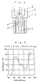
- Fig. 1 shows the sectional view of the core/cladding rod lens and the distribution of the refractive index thereof.
- the lens has a circular cross section and the lens contains the core in the center portion thereof and the coaxial cladding surrounding the core.
- a curve of distribution of the refractive index is shown below the sectional view of the lens.
- the abscissa r expresses the radial distance from the center of the core and the ordinate n expresses the refractive index.
- the glass composition of the core and the cladding before the ion exchange treatment is determined so that the refractive index continuously varies at the boundary between the core and the cladding after ion exchange treatment especially when the thickness of the layer of the cladding is made relatively larger in comparison with the diameter of the core.
- the Japanese Patent Publication S63-301901A makes disclosure of a method of preventing the entrance of the flare light in that a light absorbent layer of the glass including colorants consisting of metal ion including Mn, Cr, Co, Ni, Fe, Cu, Ag, Ti, Pb, Ru, Cd, V, Mo and the like to prevent the entrance of the flare light is formed in the cladding while producing the refractive index distribution type optical element by soaking the core/cladding glass rod respectively containing the cation of Li + and the like into the molten salt, for example the molten salt comprising the sodium nitrate, for the determined periods to exchange the lithium ion contained in the core/cladding glass rod for the sodium ion existing in the molten salt.
- a light absorbent layer of the glass including colorants consisting of metal ion including Mn, Cr, Co, Ni, Fe, Cu, Ag, Ti, Pb, Ru, Cd, V, Mo and the like to prevent the entrance of the flare light is formed in the cladding while
- the colorant used in an example of the invention of the Japanese Patent Publication S63-301901A which includes MnO, CoO or a combination of CoO and MnO is available for the optical device employing the monochromatic light for the illuminant, while it is insufficiently provided with the resolution when used for the optical device employing the white light for the illuminant.
- a refractive index distribution type optical element having a cladding glass layer consisting of a light absorbent glass including CoO, MnO and Cr 2 O 3 as the colorant, e.g. 1.5 wt. % CoO, 1.0 wt. % MnO and 0.4 wt. % Cr 2 O 3 , so as to prevent the entrance of the flare light and to improve the external diameter precision.
- the colorant easily causes devitrification to the core and the cladding glass, and it has limited applications for the glass composition of the core and the cladding glass.
- the refractive index distribution type optical element of the present invention has a core/cladding structure produced with the ion exchange method.
- the element includes colorant of metal oxides, in cladding glass.
- the cladding glass consists of base glass and the colorants of the metal oxides including:
- the refractive index distribution type rod lens array of the present invention is produced in such a manner that the plural refractive index distribution type optical elements as described above are arranged so that all optical axes thereof are mutually parallel and, then, adhered.
- the colorant of the metal oxides (hereinafter, it may simply called as the colorant) contained in the cladding glass is added to the base glass composition (the composition of the basic glass materials except for the colorant) as an extra component amount of which is expressed by weight percentage based on the total amount of the base glass of the cladding, that is, weight percentage of the colorant taking the total amount of the base glass as 100 wt. % (hereinafter, it may simply called as an " additive amount").
- the refractive index distribution type optical element of the present invention prevents the deterioration of the optical properties occurring at the portion having the refractive index departing from the regular parabolic distribution, and it also prevents the entrance of the flare light. Especially, since the light having a wavelength over the entire visible range can be effectively removed by adding CoO, Fe 2 O 3 and, if needed, NiO and/ or Cr 2 O 3 in the determined amount, the refractive index distribution type optical element containing the core/cladding structure which is provided with the good resolution even when used in the optical devices employing the white light for the illuminant can be produced.
- the metal oxide contained in the cladding glass as the colorant is selected which is in principle free of suffering the ion exchange.
- the glass varies in the density, viscosity, thermal expansivity and the like as the rise of the content of the colorant.
- a large content of the colorant easily causes devitrification while forming the core/cladding glass rod, for example during the spinning process using a double crucible.
- the content of the colorant is preferable to be possibly lowered within such a range as not to lose the absorption of the light having a determined wavelength.
- the colorant is preferable to be reduced so as to let the refractive index which is developed with the ion exchange possibly close to the parabolic distribution. From this point of view, CoO is suitable for the colorant.
- the glass When including CoO, the glass becomes liable to strongly absorb the light having a wavelength of 520 to 680 nm because of Co 2+ ion. Since the strength of the absorption depends on the content of CoO, as the content of CoO becomes large, the glass can effectively remove the light which enters the cladding layer to make no contribution to imaging.
- the content of CoO is in a range of 0.3 to 4.0 wt. %, preferably in a range 0.4 to 2.5 wt. %, more preferably in a range of 0.5 to 1.5 wt %.
- Fe 2 O 3 is preferable to be added in an amount of 1.0 to 4.0 wt. % in case that the content of MgO is equal to or higher than 5 wt. % when the total amount of the base glass is taken as 100 wt. %.
- the content of Fe 2 O 3 is preferably in a range of 1.0 to 2.5 wt. %. While, when the colorant does not include NiO, the content of Fe 2 O 3 is preferably in a range of 1.5 to 4.0 wt. %.
- Fe 2 O 3 has less absorptivity than CoO, the content of Fe 2 O 3 is preferable to be made as large as possible so that absorption of the light having a wavelength of 380 to 460 nm is developed to improve the resolution over this wavelength range.
- Fe 2 O 3 can be added in an amount up to 12.0 wt. %.
- Fe 2 O 3 is preferable to be added in an amount of 6.0 to 12.0 wt. %.
- Co 2+ ion and Fe 3+ ion are particularly incorporated in the cladding glass to effectively remove the light having wavelengths over the entire visible range.
- NiO which is not essential component, is preferable to be added because NiO absorbs the light having a wavelength in a visible range of 420 to 500 nm which extends between ranges absorbed by CoO and by Fe 2 O 3 when incorporated with CoO and Fe 2 O 3 .
- the content of NiO is preferable to be made as small as possible.
- NiO is included in an amount of 0.0 to 2.0 wt. %, preferably in an amount of 0.2 to 2.0 wt. %, more preferably 0.2 to 1.0 wt. %.
- the other metal oxide absorbing the light having a short wavelength within the visible range is known as Cr and Mn.
- Mn and Cr respectively can be added as extra complements to Co, Fe and Ni in the manner given as follows.
- Cr 2 O 3 which is not an essential component, strongly absorbs the light having a wavelength of 380 to 430 like as Fe 2 O 3 , and its absorptivity is higher than that of Fe 2 O 3 . While, Cr 2 O 3 is liable to cause devitrification to the cladding glass especially to the glass including lithium. Cr 2 O 3 can be added in an amount up to 0.2 wt. % without causing the devitrification to the glass.
- MnO which is not an essential component, strongly absorbs the light having a wavelength of 440 to 500 nm when existing in the form of Mn 3+ ion in the glass. While, when coexisting with Fe 2 O 3 , MnO exists in the form of Mn 2+ and has little or no absorptivity of the light. Therefore, though safely added in an amount up to 1.0 wt. %, MnO is not suitable for the colorant.
- the desirable composition of the base glass of the cladding containing the aforementioned colorant before ion exchange is shown as follows, provided the total amount of the base glass before the ion exchange treatment is taken as 100 wt %.
- composition of the base glass of the cladding glass (before ion exchange treatment)]
- the desirable composition of the core glass before ion exchange treatment is shown as follows, provided the total amount is taken as 100 wt. %.
- composition of the core glass (before ion exchange treatment)]
- the composition of the cladding glass and the core glass is distributed not uniformly but heterogeneously in the radial direction, particularly in respect to Li 2 O and Na 2 O.
- the base glass of the cladding and the core glass of the refractive index distribution type optical element produced with the ion exchange treatment have the "average" composition given as follows respectively. (It should be noted that a total % thereof is 100 wt. %.) It is preferable that the content of Na 2 O in the cladding glass is larger than that in the core glass and the content of Li 2 O in the core glass is more than that in the cladding glass.
- "average" means a state where the composition in the cladding glass and the core glass given as follows is supposed to be distributed uniformly.
- the refractive index distribution type optical element of the present invention can be produced in such a manner that the core/cladding glass rod is firstly produced in accordance with the conventional method using the raw cladding glass having the determined composition prepared due to adding the colorant into the base glass and the raw core glass, and then, it is exposed to the melting salt, e.g. sodium nitrate, for determined periods so as to exchange the lithium ion existing in the core/cladding glass for the sodium ion existing in the melting salt.
- the melting salt e.g. sodium nitrate
- the refractive index distribution type optical element of the present invention is preferable to consist of the core glass having a diameter of 100 to 1000 ⁇ m and the cladding glass layer having a thickness of 1 to 100 ⁇ m, provided the thickness of the cladding glass layer is preferably 1 to 25 % of the diameter of the core glass, and which has a constant of the refractive index (g) of 0.1 to 4, and the glass of the cladding glass layer having a thickness of 100 ⁇ m has transmittance of equal to or less than 75 % against the entire light having a wavelength of 380 to 680 nm.
- the refractive index distribution type rod lens array of the present invention is produced in such a manner that 50 to 1000 pieces of aforementioned refractive index distribution type optical element of the present invention are arranged in a single column or in two to four columns to form a zigzag configuration, in which the optical axes of every pieces are mutually parallel and the both ends of each piece respectively form a flat surface, and mutually adhered.
- the cladding glass having the composition shown in Table 1 and 3, which is in form of a hollow cylindrical shape having a thickness of 0.5 mm and an internal diameter of 30.5 mm, and the core glass rod having a diameter of 30 mm which is inserted thereinto are heated in the electric furnace at 650 °C and drawn by the drawing roller so that the cladding glass having a hollow cylindrical shape and the core glass rod are welded and integrated each other to form a core/cladding glass rod having an external diameter of 300 ⁇ m and a diameter of the core of 295 ⁇ m (a layer of the cladding is to have a thickness of 2.5 ⁇ m).
- the amount of the colorant is expressed as percent by weight taking the total amount of the base glass except for the colorant as 100 wt. %
- the glass rod After being cut into a piece having a length of about 1 m, the glass rod is soaked to the molten salt of sodium nitrate maintained at about 445 °C for about 24 hours in a bath so as to exchange the lithium ion existing in the glass rod and the sodium ion existing in the molten salt. After that, the rod lens is taken out of the bath to be cut and polished in the both ends thereof so as to form a rod lens having a length of 4.13 or 4.01 mm which has distribution of the refractive index.
- the refractive index exhibits a continuous variation at the boundaries between the core and the cladding.
- the rod lens array is measured in the value of MTF (Modulation Transfer Function) over the wavelength of 470 nm, 530 nm and 660 nm taking the spacial frequency of the grid pattern as 12 Lp/mm and using the white light as the illuminant.
- MTF Modulation Transfer Function
- Table 4 MTF expresses the ratio of contrast between an object and an image thereof as a function of the spacial frequency. As MTF approaches 100 %, the origin is faithfully reproduced on the image with a high resolution.
- Double structured glass rods of which the core and the cladding contain the composition of shown in Table 1 and 2 are produced by spinning process using a double crucible in the manner as follows.
- the double crucible 1 comprises an inner crucible 2 and an outer crucible 3.
- the glass cullet for the core glass is fed into the inner crucible 2 and that for the cladding glass is fed into the outer crucible 3, and which are heated and melted respectively in the crucible 1.
- the core glass 4 is pulled out of the inner crucible 2 and the cladding glass 5 containing the colorant is pulled out of the outer crucible 3 respectively from a lower nozzle 6 to make the core/cladding glass rod by using the drawing roller (not shown) so that the core glass and the cladding glass are welded each other to be integrated.
- Each of the resulted glass rods is treated with the ion exchange process in the same manner as Example 1 to produce the rod lens and the rod lens array thereof and the optical properties thereof are measured and shown in Table 4.
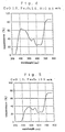
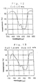
- the spectral transmittance characteristics of the cladding glass of Example 1 (containing 1.0 wt. % CoO and 3.0 wt. % Fe 2 O 3 ) is shown in Fig. 3 (in which the thickness of the glass is expressed as 0.1 mm)
- Example 3 (containing 1.0 wt. % CoO, 2.0 wt. % Fe 2 O 3 and 0.5 wt. % NiO) is shown in Fig. 4 (in which the thickness of the glass is expressed as 0.1 mm)
- Example 4 (containing 1.0 wt. % CoO and 10.0 wt. % Fe 2 O 3 ) is shown in Fig.
- Example 5 (in which the thickness of the glass is expressed as 0.1 mm), Example 5 (containing 1.0 wt. % CoO, 6.0 wt. % Fe 2 O 3 and 1.0 wt. % NiO) is shown in Fig. 6 (in which the thickness of the glass is expressed as 0.1 mm), Example 6 (containing 2.0 wt. % CoO and 6.0 wt. % Fe 2 O 3 ) is shown in Fig. 7 (in which the thickness of the glass is expressed as 0.1 mm), Example 7 (containing 3.5 wt. % CoO and 3.0 wt. % Fe 2 O 3 ) is shown in Fig. 8 (in which the thickness of the glass is expressed as 0.1 mm), Example 8 (containing 3.5 wt.
- Fig. 9 in which the thickness of the glass is expressed as 0.1 mm
- Example 9 containing 1.0 wt. % CoO, 3.0 wt. % Fe 2 O 3 and 1.75 wt. % NiO
- Fig. 10 in which the thickness of the glass is expressed as 0.1 mm
- Example 10 containing 1.0 wt. % CoO, 10.0 wt. % Fe 2 O 3 and 1.75 wt. % NiO
- Fig. 11 in which the thickness of the glass is expressed as 0.1 mm
- Comparative Example 1 containing 1.0 wt. % CoO is shown in Fig.
- Comparative Example 3 (containing 1.0 wt. % CoO and 0.5 wt. % NiO) is shown in Fig. 13 (in which the thickness of the glass is expressed as 1 mm).
- Examples 1 through 10 are provided with high values of MTF over wavelengths of 470 nm, 530 mm and 660 nm respectively.
- Comparative Examples 1, 3 and 4 have low values of MTF at a wavelength of 470 nm, and it exhibits that these Comparative Examples are lowered in resolution when the white light is employed for the illuminant.
- Examples 1 and 2 While being identical to each other in the composition of the colorant and different from each other in that of the base glass of the core and the cladding, Examples 1 and 2 are free of devitrification. In contrast, despite the same composition of the base glass of the core and the cladding as Example 1, devitrification occurs in Comparative Example 2.
- a refractive index distribution type rod lens which has the exceedingly high external diameter precision, and which is less or not affected by the light passing through the peripheral portion where the refractive index is disorderly distributed, and prevents the entrance of the flare light so as to provide the good resolution even when used in the optical device employing the white light for the illuminant, and a rod lens array thereof can be provided by treating a double glass rod, which has the core/cladding structure and contains the colorant comprising at least Co and Fe in the cladding glass, with the ion exchange process.
Landscapes
- Chemical & Material Sciences (AREA)
- Life Sciences & Earth Sciences (AREA)
- Engineering & Computer Science (AREA)
- Chemical Kinetics & Catalysis (AREA)
- General Chemical & Material Sciences (AREA)
- Geochemistry & Mineralogy (AREA)
- Materials Engineering (AREA)
- Organic Chemistry (AREA)
- Physics & Mathematics (AREA)
- Optics & Photonics (AREA)
- General Physics & Mathematics (AREA)
- Glass Compositions (AREA)
Applications Claiming Priority (5)
| Application Number | Priority Date | Filing Date | Title |
|---|---|---|---|
| JP20211398 | 1998-07-16 | ||
| JP20211398 | 1998-07-16 | ||
| JP7075799 | 1999-03-16 | ||
| JP7075799 | 1999-03-16 | ||
| PCT/JP1999/003748 WO2000004409A1 (fr) | 1998-07-16 | 1999-07-12 | Element optique du type a distribution de l'indice de refraction et ensemble lentille barreau du type a distribution de l'indice de refraction |
Publications (2)
| Publication Number | Publication Date |
|---|---|
| EP1018657A1 true EP1018657A1 (fr) | 2000-07-12 |
| EP1018657A4 EP1018657A4 (fr) | 2007-06-27 |
Family
ID=26411892
Family Applications (1)
| Application Number | Title | Priority Date | Filing Date |
|---|---|---|---|
| EP99929789A Withdrawn EP1018657A4 (fr) | 1998-07-16 | 1999-07-12 | Element optique du type a distribution de l'indice de refraction et ensemble lentille barreau du type a distribution de l'indice de refraction |
Country Status (5)
| Country | Link |
|---|---|
| US (1) | US6141155A (fr) |
| EP (1) | EP1018657A4 (fr) |
| CN (1) | CN1135411C (fr) |
| TW (1) | TW405045B (fr) |
| WO (1) | WO2000004409A1 (fr) |
Cited By (3)
| Publication number | Priority date | Publication date | Assignee | Title |
|---|---|---|---|---|
| US8193108B2 (en) | 2004-07-23 | 2012-06-05 | Nippon Sheet Glass Company, Limited | Clad glass composition and mother glass rod for gradient-index rod lens formed using the same, gradient-index rod lens and method of manufacturing the same, rod lens array, and image processor |
| EP1925951A4 (fr) * | 2005-08-08 | 2013-07-17 | Isuzu Glass Co Ltd | Procédé de fabrication d un élément optique à indice de gradient ayant une capacité d absorption de l infrarouge |
| CN103570248A (zh) * | 2012-07-20 | 2014-02-12 | 中国科学院理化技术研究所 | 增透的防雾玻璃及其制备方法 |
Families Citing this family (6)
| Publication number | Priority date | Publication date | Assignee | Title |
|---|---|---|---|---|
| JP3781404B2 (ja) * | 2000-03-31 | 2006-05-31 | キヤノン株式会社 | 画像形成装置 |
| JP2002121048A (ja) * | 2000-10-11 | 2002-04-23 | Nippon Sheet Glass Co Ltd | 屈折率分布型レンズ用母材ガラス組成物 |
| TW200405139A (en) * | 2002-09-04 | 2004-04-01 | Nippon Sheet Glass Co Ltd | Glass composition for graded-index rod lens cover, graded-index rod lens, and method for manufacturing the same |
| FR2871796B1 (fr) * | 2004-06-21 | 2006-09-15 | Alcatel Sa | Procede et installation de fabrication d'un element fibre a filtre de lumiere selectif |
| JP2006106324A (ja) | 2004-10-05 | 2006-04-20 | Nippon Sheet Glass Co Ltd | 屈折率分布型ロッドレンズ、およびその製造方法 |
| CN109633813B (zh) * | 2018-12-21 | 2020-05-22 | 中国建筑材料科学研究总院有限公司 | 一种光纤传像元件及其制备方法 |
Family Cites Families (4)
| Publication number | Priority date | Publication date | Assignee | Title |
|---|---|---|---|---|
| JP2557388B2 (ja) * | 1987-06-02 | 1996-11-27 | キヤノン株式会社 | 屈折率分布型光学素子およびその製造方法 |
| FR2672884B1 (fr) * | 1991-02-20 | 1993-09-10 | Saint Gobain Vitrage Int | Couche protectrice sur un substrat conducteur. |
| JP3396118B2 (ja) * | 1995-11-02 | 2003-04-14 | オリンパス光学工業株式会社 | 屈折率分布型光学素子及び屈折率分布型光学素子を用いた光学機器 |
| JPH10139472A (ja) * | 1996-11-06 | 1998-05-26 | Nippon Sheet Glass Co Ltd | コア/クラッド構造の屈折率分布型光学素子のクラッド用ガラス組成物 |
-
1999
- 1999-07-12 WO PCT/JP1999/003748 patent/WO2000004409A1/fr not_active Ceased
- 1999-07-12 CN CNB998011592A patent/CN1135411C/zh not_active Expired - Lifetime
- 1999-07-12 EP EP99929789A patent/EP1018657A4/fr not_active Withdrawn
- 1999-07-13 TW TW088111883A patent/TW405045B/zh not_active IP Right Cessation
-
2000
- 2000-02-22 US US09/511,639 patent/US6141155A/en not_active Expired - Lifetime
Non-Patent Citations (2)
| Title |
|---|
| No further relevant documents disclosed * |
| See also references of WO0004409A1 * |
Cited By (4)
| Publication number | Priority date | Publication date | Assignee | Title |
|---|---|---|---|---|
| US8193108B2 (en) | 2004-07-23 | 2012-06-05 | Nippon Sheet Glass Company, Limited | Clad glass composition and mother glass rod for gradient-index rod lens formed using the same, gradient-index rod lens and method of manufacturing the same, rod lens array, and image processor |
| EP1925951A4 (fr) * | 2005-08-08 | 2013-07-17 | Isuzu Glass Co Ltd | Procédé de fabrication d un élément optique à indice de gradient ayant une capacité d absorption de l infrarouge |
| CN103570248A (zh) * | 2012-07-20 | 2014-02-12 | 中国科学院理化技术研究所 | 增透的防雾玻璃及其制备方法 |
| CN103570248B (zh) * | 2012-07-20 | 2016-04-06 | 中国科学院理化技术研究所 | 增透的防雾玻璃及其制备方法 |
Also Published As
| Publication number | Publication date |
|---|---|
| US6141155A (en) | 2000-10-31 |
| WO2000004409A1 (fr) | 2000-01-27 |
| CN1135411C (zh) | 2004-01-21 |
| EP1018657A4 (fr) | 2007-06-27 |
| CN1274428A (zh) | 2000-11-22 |
| TW405045B (en) | 2000-09-11 |
Similar Documents
| Publication | Publication Date | Title |
|---|---|---|
| KR101514086B1 (ko) | 파이버 옵틱 | |
| EP1452495B1 (fr) | Verre aluminosilicaté | |
| JP4464162B2 (ja) | ホウ素アルミノシリケートガラス | |
| TWI407135B (zh) | 結構體及其製造方法 | |
| JP3488483B2 (ja) | 影像伝達用光ファイバアレイと導波管像伝達アレイおよびその端面の処理法 | |
| US6141155A (en) | Refractive index distribution type optical element and refractive index distribution type rod lens array | |
| JP2006056768A (ja) | 屈折率分布型ロッドレンズ用クラッドガラス組成物、およびそれを用いた屈折率分布型ロッドレンズ母ガラスロッド、ならびに屈折率分布型ロッドレンズ、およびその製造方法 | |
| US4971423A (en) | Gradient-index-type optical device | |
| EP0927705B1 (fr) | Plaque de verre optique | |
| EP0248564B1 (fr) | Guides d'ondes optiques et leur fabrication | |
| JP4013913B2 (ja) | 鉛フリーの屈折率分布型レンズ用母材ガラス組成物、屈折率分布型レンズ、屈折率分布型レンズの製造方法、光学製品及び光学機器 | |
| US5076825A (en) | Method of producing optical multiple fiber | |
| JP4046786B2 (ja) | ファイバオプティックプレート | |
| US5259057A (en) | Waveguide array and method for contrast enhancement | |
| CN119414516A (zh) | 一种对比度增强型光纤倒像器及其制备方法 | |
| JPH10139472A (ja) | コア/クラッド構造の屈折率分布型光学素子のクラッド用ガラス組成物 | |
| JPH0971436A5 (fr) | ||
| JP2001255406A (ja) | 屈折率分布型光学素子および屈折率分布型ロッドレンズアレイ | |
| JPWO2000004409A1 (ja) | 屈折率分布型光学素子および屈折率分布型ロッドレンズアレイ | |
| JP4060568B2 (ja) | 吸収体ガラス及びファイバオプティックプレート | |
| JPH0335642B2 (fr) | ||
| JPH07174923A (ja) | 耐放射線性石英系イメージファイバ |
Legal Events
| Date | Code | Title | Description |
|---|---|---|---|
| PUAI | Public reference made under article 153(3) epc to a published international application that has entered the european phase |
Free format text: ORIGINAL CODE: 0009012 |
|
| 17P | Request for examination filed |
Effective date: 20000315 |
|
| AK | Designated contracting states |
Kind code of ref document: A1 Designated state(s): DE FR GB |
|
| A4 | Supplementary search report drawn up and despatched |
Effective date: 20070531 |
|
| STAA | Information on the status of an ep patent application or granted ep patent |
Free format text: STATUS: THE APPLICATION IS DEEMED TO BE WITHDRAWN |
|
| 18D | Application deemed to be withdrawn |
Effective date: 20070830 |