EP1018677A1 - Virtuelles Teach-In-System - Google Patents
Virtuelles Teach-In-System Download PDFInfo
- Publication number
- EP1018677A1 EP1018677A1 EP99121530A EP99121530A EP1018677A1 EP 1018677 A1 EP1018677 A1 EP 1018677A1 EP 99121530 A EP99121530 A EP 99121530A EP 99121530 A EP99121530 A EP 99121530A EP 1018677 A1 EP1018677 A1 EP 1018677A1
- Authority
- EP
- European Patent Office
- Prior art keywords
- workpiece
- tool
- program
- machine
- data
- Prior art date
- Legal status (The legal status is an assumption and is not a legal conclusion. Google has not performed a legal analysis and makes no representation as to the accuracy of the status listed.)
- Granted
Links
Images






Classifications
-
- G—PHYSICS
- G05—CONTROLLING; REGULATING
- G05B—CONTROL OR REGULATING SYSTEMS IN GENERAL; FUNCTIONAL ELEMENTS OF SUCH SYSTEMS; MONITORING OR TESTING ARRANGEMENTS FOR SUCH SYSTEMS OR ELEMENTS
- G05B19/00—Program-control systems
- G05B19/02—Program-control systems electric
- G05B19/18—Numerical control [NC], i.e. automatically operating machines, in particular machine tools, e.g. in a manufacturing environment, so as to execute positioning, movement or co-ordinated operations by means of program data in numerical form
-
- G—PHYSICS
- G05—CONTROLLING; REGULATING
- G05B—CONTROL OR REGULATING SYSTEMS IN GENERAL; FUNCTIONAL ELEMENTS OF SUCH SYSTEMS; MONITORING OR TESTING ARRANGEMENTS FOR SUCH SYSTEMS OR ELEMENTS
- G05B19/00—Program-control systems
- G05B19/02—Program-control systems electric
- G05B19/18—Numerical control [NC], i.e. automatically operating machines, in particular machine tools, e.g. in a manufacturing environment, so as to execute positioning, movement or co-ordinated operations by means of program data in numerical form
- G05B19/4093—Numerical control [NC], i.e. automatically operating machines, in particular machine tools, e.g. in a manufacturing environment, so as to execute positioning, movement or co-ordinated operations by means of program data in numerical form characterised by part programming, e.g. entry of geometrical information as taken from a technical drawing, combining this with machining and material information to obtain control information, named part program, for the NC machine
- G05B19/40937—Numerical control [NC], i.e. automatically operating machines, in particular machine tools, e.g. in a manufacturing environment, so as to execute positioning, movement or co-ordinated operations by means of program data in numerical form characterised by part programming, e.g. entry of geometrical information as taken from a technical drawing, combining this with machining and material information to obtain control information, named part program, for the NC machine concerning programming of machining or material parameters, pocket machining
-
- Y—GENERAL TAGGING OF NEW TECHNOLOGICAL DEVELOPMENTS; GENERAL TAGGING OF CROSS-SECTIONAL TECHNOLOGIES SPANNING OVER SEVERAL SECTIONS OF THE IPC; TECHNICAL SUBJECTS COVERED BY FORMER USPC CROSS-REFERENCE ART COLLECTIONS [XRACs] AND DIGESTS
- Y02—TECHNOLOGIES OR APPLICATIONS FOR MITIGATION OR ADAPTATION AGAINST CLIMATE CHANGE
- Y02P—CLIMATE CHANGE MITIGATION TECHNOLOGIES IN THE PRODUCTION OR PROCESSING OF GOODS
- Y02P90/00—Enabling technologies with a potential contribution to greenhouse gas [GHG] emissions mitigation
- Y02P90/02—Total factory control, e.g. smart factories, flexible manufacturing systems [FMS] or integrated manufacturing systems [IMS]
Definitions
- the invention relates generally to a system for generating, Change and / or visualization of programs for machine control.
- the Invention a system for creating, changing and / or Visualization of programs for the control of Grinding machines.
- Machine tools are usually program-controlled, i.e. machining operations to be carried out on a workpiece run programmatically.
- program-controlled i.e. machining operations to be carried out on a workpiece run programmatically.
- NC axes are provided.
- NC-controlled drive numerically controlled.
- By actuation one or more of these axes creates an infeed movement.
- grinding spiral grooves on drilling tools is an overlay of several motion components required a suitable relative movement between the workpiece and the tool.
- EP 0530364 A1 an interactive numerical control, which on a monitor is a representation of a workpiece based on existing NC data.
- An interactive one Changes to the NC data can be displayed immediately to be brought. This will impact data changes immediately visible.
- the system includes storage means, Computing means, display means and input means. Based on the representation of the machining process on one Monitor, the NC data can be corrected directly on the screen become.
- NC machines require in the Usually certain knowledge of both the programming language used as well as the special circumstances when machining certain surfaces of the workpiece.
- the invention System has a teach-in module, for example. through a program running on suitable hardware can be formed.
- the teach-in module allows a visual, preferably three-dimensional representation of a Workpiece and a tool. This is also possible if no machine control program is yet available is. It is then used as a workpiece, for example or a tool that has not been fully machined.
- the blank or the partially machined tool can For example kept in a library and this be taken.
- the teach-in module can be used with appropriate Scaling functions are provided to the visual Representation of the tools, blanks or basic body too a desired size and a required dimensional ratio bring to.
- the teach-in module is set up for this purpose manual entries a user-specified Relative movement of the workpiece and the tool in relation visually on top of each other.
- E.g. can the movements as single movement steps or as a given
- the following movements can be entered.
- the default One way can be, for example, in a library prepared typical paths, e.g. straight lines, helical lines or similar ways.
- a scaling function can be provided.
- you can use smoothing functions over a manually entered route become.
- One component of the teach-in module is that based on the relative movement entered in the teach-in module between a representation of the tool and one Representation of the workpiece in a machine control program is created or modified.
- the teach-in module caused by the relative movement between the workpiece resulting processing progress, i.e. on the blank, For example, by means of a grinding wheel, generated virtually Displays recesses, the machine control data at the same time generated that correspond to such processing.
- virtual teach-in the machine control program are generated. Is the machine control program already exists, it can be done through the virtual teach-in procedures can be modified. In order to the operation of a corresponding numerical is simplified controlled machine tool considerably.
- machine control programs In a simple way, which are both the sequence of movements and the Speeds of the axes of a grinding machine as also state changes at the inputs of a control unit, e.g. describe a PLC control unit (e.g. the Switching the coolant valves on or off Grinding wheel spindle).
- PLC control unit e.g. the Switching the coolant valves on or off Grinding wheel spindle
- Such machine control programs usually consist of a series of individual commands about individual movements of the machine axes as well from PLC control commands.
- Program lines and from several Program blocks formed by program lines control the Movement of one or more axes between two points in the room.
- the virtual teach-in module now allows e.g. the change of existing program lines or existing, blocks composed of several program lines, the addition of new program lines or blocks as well as the Deletion of existing program lines or blocks.
- the virtual teach-in module preferably has a storage device that is used to store workpiece data, for storing tool data and for storing of work instructions on the relative movements between tool and workpiece.
- a storage device that is used to store workpiece data, for storing tool data and for storing of work instructions on the relative movements between tool and workpiece.
- a hardware-related memory under the Management of a corresponding program or program section provided that processed on a suitable computer becomes.
- This also contains a computing device for which a corresponding program section as well as the Program or hardware executing the program section heard.
- the computing means processes those in the storage means existing and provided work instructions, the workpiece data and / or the tool data to change according to the work instructions or to complete how it is machining the workpiece through the tool according to the through the work instructions fixed relative movement corresponds. In this way can, for example, material removal and / or tool wear be modeled.
- Display means for which a display device and include the appropriate program that serves To make data on the display device graphically visible.
- An input means is used to record the desired ones Relative movements between tool and workpiece, the are implemented in corresponding work instructions that again stored or buffered by the storage means become.
- Input devices can be used for the input means as well as a playback device on which virtual input buttons belong or the like can be represented.
- the input means for example by a special Input device or an input device in connection with input fields shown on a screen can be assigned to individual machine axes Control panels as well as control panels for configurable Contain axes that do not match machine axes. This further simplifies operation.
- the teach-in module can be in a simulation module contained or connected to one that the Presentation of the entered processing in the manner of a Films allowed.
- the simulation can also be carried out step by step as well as in slow motion or fast motion.
- the Simulation can be interrupted and with the teach-in module be corrected if necessary.
- Such Means can be formed, for example, by a cursor, with points of the workpiece can be selected at will, d. H. are responsive, the means then dimensional relationships determined between the points.
- the display provided by the display means is preferably a 3D representation that unites the viewer gives a spatial impression of the virtually created workpiece.
- the system according to the invention can, for example, on a operated separately or in the control of one NC-controlled machine can be integrated.
- NC programs for NC controlled machines can be interactive be created, after which the program thus created transferred to the otherwise conventional NC machine becomes. Data carriers or data lines can be used for this.
- the system 1 illustrates a teach-in system 1 which is used to generate, change and visualize programs for machine control.
- the system 1 has a teach-in module 2, which is used for the interactive creation of machine control programs.
- the teach-in module 2 is formed by a computer program and the underlying hardware. It has a program part 4 which is set up to act on data schematically identified in FIG. 1 by a block 5 and on a machine control program.
- the teach-in module has a collision module 2a as shown in FIG. 3 and a time calculation module 2b.
- the collision module 2a serves to prevent undesirable collisions between Determine tool and workpiece that are not touching in the sense of (machining) workpiece machining.
- the time calculation module 2b is used to determine the machining time that will result when the machine control program is actually processed.
- the data can have been fed to the teach-in module 2 from a block 6, which can, for example, contain data that represent an unprocessed workpiece. If the output data are transferred from block 6 to block 5, these are transferred from block 5 to the teach-in module 2 for the display and manipulation of the display. On the basis of the manipulation of the representation, the data and the machine program in block 5 are again acted upon until the desired data record and the desired machine program have been generated. This is then output as a machine control program, as illustrated by a block 7 in FIG. 1.
- the teach-in module 2 includes a computer with a control and processing unit, which forms a computing unit 11 Memory 12, a monitor 14 and an input device 15.
- memory 12 forms one on the computing unit 11 running program 16 a storage unit 17 for storing workpiece data, tool data and Instructions that have a relative movement between tool and mark the workpiece.
- Another section of the Program 16 forms a display means with the monitor 14 18 for the visualization of the workpiece, the tool and the relative position of workpiece and tool to each other.
- the teach-in system is operated via another Section of program 16 in connection with the Input device 15 and the monitor 14.
- the one in question Program section forms with the input device 15 and the Monitor 14 an input means 19.
- the so far described Teach-in system 2 works as follows:
- step 5 is created in block 5 a machine control program. If workpiece and tool have gone through all the required positions is the Teach-in process ended, and in block 7 the finished Machine control program issued, so to speak through the track of the relative movement of workpiece display and tool display is defined.
- the machine control program can now be directly connected to a machine tool transferred, which it then processes.
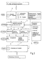
- the teach-in system in FIG. 3 is the data flow of the Systems illustrated schematically. It is only a program section illustrates.
- the communication the virtual teach-in system with other system components and the system start is controlled by a higher-level, program not illustrated further perceived. This includes, for example, the transfer of the generated Machine control program to the machine.
- Machine control program are in a processing module Traverse paths generated by machine axes. In figure 3 this is for five different axes X, Y, Z, A and C illustrated.
- the processing module also receives Data on machine geometry and kinematics that Washer geometry, clamping device and the workpiece geometry. It is also connected to the input means with which the user make an operation, the processing interrupt or continue and, if necessary, program lines or add, delete or change blocks specifically can.
- the processing module creates from this data Workpiece model, carries out a collision analysis and calculates the processing time required. This as well as the collision analysis and the workpiece model are visualized by the display means. The generated Travel paths are transferred to the storage medium and thus recorded on the hard disk. You can as Transfer machine control program to the machine or in transformed a machine control program and then on the machine will be transferred.
- the machine is shown schematically in Figure 5 in plan view illustrated. It has a machine bed 21 a workpiece carrier 22 about a vertical axis C is pivotally mounted.
- the workpiece carrier 22 is also by means of another NC axis X in a horizontal direction adjustable. He also wears a cradle 24 for a workpiece 25, for example a drilling tool. If necessary, a rotary positioning device can be mounted on the receiving device 24 be provided which is another Represents NC axis A.
- a grinding head 26 is also provided in the vicinity of the workpiece carrier 22 and carries one or more grinding wheels 27, 28, 29. If necessary, the grinding head 26 can be adjusted in a direction coinciding with the axis of rotation of the grinding spindle by means of an NC axis Z and linearly in a direction parallel to the C axis (NC axis Y).
- the workpiece 25 is not linearly adjustable with respect to the workpiece carrier 22.
- An axial movement (from the point of view of the grinding wheels 27, 28, 29) of the workpiece 25 in the direction X ' can be achieved by superimposing movements in the Z direction (grinding head movement) and in the X direction (workpiece carrier movement).
- the virtual teach-in module whose user interface is illustrated in FIG. 6, is used for interactive teach-in programming of this NC machine.
- the illustration illustrates a control panel 31 for display by the display means 14 on a monitor.
- the control panel 31 contains several control key fields 32 and display fields 33.
- the control key fields include key fields X, Y, Z, A, C for selecting NC axes of the grinding machine. Keys -" and + “as well E "for rapid traverse are used to control the movement.
- the current feed increment can be set in linear steps or angular steps.
- a repeat button ReDo restores the previously deleted step.
- control button field K which identifies a configurable axis, which can differ from the actually existing NC axes and can be assembled by superimposing the movement of the various actually existing machine axes X, Y, Z, A, C.
- All movements are understood and carried out as linear movements between two points in space. Changes in angular coordinates are represented by linear changes in angle.
- the movements of the machine axes can either be carried out as one axis or the simultaneous movement of several axes. An axis is selected for the individual movement and moves according to the selected feed and the number of repetitions of the incremental movements by the associated distance.
- the simultaneous movement of several axes can be described by the series connection of single axis movements.
- the mode Multi-axis movement "is switched on and the axes are moved one after the other to the desired end point. The mode is then activated Multi-axis movement "switched off and all (linear) movements since switching on Multi-axis movement "combined into a simultaneous movement of all axes involved.
- configurable axis This is composed of the machine axes.
- the configurable axis does not exist as a real axis. The movement along this axis must be generated by simultaneous movement of one or more machine axes. In most cases, it is advisable to use a configurable axis Axis in the center axis of the workpiece. This means that the tool (grinding wheel) can move parallel to the workpiece axes. Movement of the grinding wheel along this axis is therefore always parallel to the longitudinal axis of the workpiece and no longer has to be programmed as a combination movement of two machine axes. 5.
- the configurable axis is operated like a machine axis, but in the machine control program (NC program) this movement is composed of the existing machine axes.
- the configurable axes are defined by given a configuration file.
- the configuration file can be modified via a menu. So you can the configurable axes easily to different Machine configurations or also to the needs of special ones Tools or workpieces can be adjusted.
- Here defines how the respective configurable axis in the Space is aligned and like this with the machine axes is coupled.
- FIGS. 6 to 14 The recording of desired workpiece movements can be seen in FIGS. 6 to 14.
- an existing machine control program is assumed. This can be visualized using a simulation run.
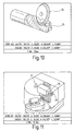
- the result of the simulation can, for example, be a workpiece view illustrated in FIG. 10.
- the NC program can remain unchanged.
- the simulation run can be interrupted at a desired point and switched to the virtual teach-in mode. This is illustrated in Figures 13 and 14.
- the PLC status is influenced accordingly. For example, the grinding wheel spindle or the coolant valves are switched on and off.
- This Responses can be illustrated in a PLC status monitor as shown in FIG. 15.
- the condition monitor illustrates the current status of the PLC inputs and outputs. The state of the outputs can be changed by appropriate controls, whereby these changes are then transferred to the current NC program become.
- the workpiece model as well as the machine and that Disk models can be measured at any time with the mouse become. Points in space are clicked on Surface or edge selected, their distance or angle to each other on the screen.
- a two-dimensional Sectional view of the workpiece are generated, which is then can be measured.
- the level can either any or according to a boundary condition e.g. parallel be selected for the X axis.
- a boundary condition e.g. parallel be selected for the X axis.
- a section perpendicular to the longitudinal axis of the workpiece Stud width or the rake angle of the chip space measured become.
- the modeling may be useful the desired workpiece by manipulating one generated by the movement of the grinding wheel through the room to allow (swept) area.
- the track the grinding wheel (swept surface) gives a volume that can be moved and rotated as required.
- the restriction the shifts and rotations due to boundary conditions, For example, the displacement of the volume a coordinate axis, until this at least the workpiece Touching a point can simplify modeling.
- Other contact surfaces for example levels, are possible.
- the desired machine control program completely created or completed.
- a virtual teach-in module for programming Contains grinding machines or other machine tools a graphical user interface. This includes the visual representation of blanks, workpieces and / or tools. The elements shown are through corresponding controls arbitrarily in relation to each other slidable. The resulting shifts are recorded by the virtual teach-in module and translated into a machine control program or it becomes a existing machine control program based on the displacements changed.
Landscapes
- Engineering & Computer Science (AREA)
- Physics & Mathematics (AREA)
- Human Computer Interaction (AREA)
- Manufacturing & Machinery (AREA)
- General Physics & Mathematics (AREA)
- Automation & Control Theory (AREA)
- Geometry (AREA)
- Numerical Control (AREA)
- Surgical Instruments (AREA)
- Electrical Discharge Machining, Electrochemical Machining, And Combined Machining (AREA)
Abstract
Description
- Fig. 1
- ein System zur Erzeugung, Veränderung und/oder Visualisierung von Maschinensteuerungsprogrammen, in einer groben Übersichtsdarstellung;
- Fig. 2
- eine Veranschaulichung einzelner zu dem Teach-In-Modul gehörender Elemente, in grober Übersichtsdarstellung;
- Fig. 3
- den Datenfluß des Teach-In-Moduls als Blockschaltbild;
- Fig. 4
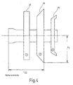
- ein Element des Werkzeugsatzes, in schematisierter bildlicher Darstellung;
- Fig. 5
- eine Schleifmaschine und deren reale sowie konfigurierbare Achse in einer schematisierten Draufsicht;
- Fig. 6
- ein Bedienpanel zur Eingabe von gewünschten Relativbewegungen zwischen dem virtuellen Werkzeug und dem virtuellen Werkstück;
- Fig. 7 bis 9
- jeweils eine Bildschirmdarstellung des virtuellen Werkzeugs und des virtuellen Werkstücks bei der Bewegungseingabe;
- Fig. 10
- eine Bildschirmdarstellung des Werkzeugs und des Werkstücks bei der Eingabe gewünschter Bearbeitungsoperationen;
- Fig. 11
- eine Bildschirmdarstellung der Maschine zur Durchführung der Bearbeitungsoperationen nach Fig. 7 bis 10;
- Fig. 12
- ein Bedienpanel für das Simulationsmodul;
- Fig. 13
- eine Bildschirmdarstellung während des Simulationslaufs;
- Fig. 14
- einen Ausschnitt aus der Bildschirmdarstellung nach Fig. 13 und
- Fig. 15
- die Bildschirmdarstellung eines SPS-Monitors.
Werkzeug und Werkstück, die keine Berührung im Sinne einer (spanenden) Werkstückbearbeitung darstellen, zu ermitteln. Das Zeitberechnungsmodul 2b dient der Bestimmung der Bearbeitungszeit, die sich bei tatsächlicher Abarbeitung des Maschinensteuerprogramms ergeben wird. Die Daten können dem Teach-In-Modul 2 aus einem Block 6 zugeführt worden sein, der bspw. Daten enthalten kann, die ein unbearbeitetes Werkstück abbilden. Sind die Ausgangsdaten von dem Block 6 an den Block 5 übergeben, werden diese von dem Block 5 dem Teach-In-Modul 2 zur Darstellung und Manipulation der Darstellung übergeben. Anhand der Manipulation der Darstellung wird wiederum auf die Daten und das Maschinenprogramm in Block 5 zurückgewirkt bis der gewünschte Datensatz und das gewünschte Maschinenprogramm erzeugt ist. Dieses wird dann als Maschinensteuerprogramm ausgegeben wie in Fig. 1 durch einen Block 7 veranschaulicht ist.

Claims (23)
- System (1) zur Erzeugung, Veränderung und/oder Visualisierung von Programmen zur Maschinensteuerung, insbesondere zur Steuerung von Schleifmaschinen,mit einem Teach-In-Modul (2), das eine visuelle Darstellung eines Werkstücks (25) und eines Werkzeugs (27, 28, 29) erbringt, die Manipulation der Darstellung durch Bewegung des dargestellten Werkstücks (25) und des dargestellten Werkzeugs (27, 28, 29) zueinander gestattet und anhand der Manipulation ein Maschinensteuerprogramm (NC-Programm) erzeugt oder verändert.
- System nach Anspruch 1, dadurch gekennzeichnet, dass das Teach-In-Modul folgende Elemente aufweist:ein Speichermittel (17),das zur Speicherung von Werkstückdaten eingerichtet ist, die ein Werkstück in einem Bearbeitungszustand kennzeichnen,das außerdem zur Speicherung von Werkzeugdaten eingerichtet ist, die ein Werkzeug kennzeichnen, unddas zur Speicherung von Anweisungen eingerichtet ist, die ein oder mehrere Relativbewegungen zwischen Werkzeug und Werkstück kennzeichnen,ein Rechenmittel (16), das dazu eingerichtet ist, anhand der Anweisungen die Werkstückdaten und/oder die Werkzeugdaten und/oder Daten über die Position von Werkstück und Werkzeug in einer Weise zu verändern, die einer Bearbeitung des Werkstücks (25) durch das Werkzeug (27) gemäß der Relativbewegung entspricht,ein Anzeigemittel (18), das dazu eingerichtet ist, anhand der Werkstückdaten und der Werkzeugdaten eine visuelle Darstellung des Werkzeugs und des Werkstücks sowie seiner Relativbewegung zu geben, undein Eingabemittel (19), das dazu eingerichtet ist, die von dem Anzeigemittel darzustellende Relativbewegung zwischen Werkzeug (27) und Werkstück (25) und dementsprechend die Anweisungen zu ändern, die die Relativbewegungen kennzeichnen.
- System nach Anspruch 2, dadurch gekennzeichnet, dass ein Transformationsmittel zur Umwandlung der Anweisungen in das Maschinensteuerprogramm (NC-Programm) vorgesehen ist.
- System nach Anspruch 2, dadurch gekennzeichnet, dass die Anweisungen durch eine Folge von Programmbefehlen gebildet sind, die das Maschinensteuerprogramm bilden.
- System nach Anspruch 1, dadurch gekennzeichnet, dass bei der Manipulation der Darstellung das Maschinensteuerprogramm verändert wird.
- System nach Anspruch 5, dadurch gekennzeichnet, dass bei der Veränderung des Maschinensteuerprogramms Informationen oder Daten über die Richtung, den Weg und/oder die Geschwindigkeit einer Bewegung des Werkstücks und/oder des Werkzeugs geändert werden.
- System nach Anspruch 2 und 3, dadurch gekennzeichnet, dass das Transformationsmittel Teil des Rechenmittels (16) ist.
- System nach Anspruch 2, dadurch gekennzeichnet, dass das Speichermittel (17), das Rechenmittel (16), das Anzeigemittel (18) und das Eingabemittel (19) jeweils ein Programm oder ein Programmabschnitt in Verbindung mit dem von ihm genutzten Teil eines Rechners ist.
- System nach Anspruch 2, dadurch gekennzeichnet, dass das Eingabemittel (19) ein als manuelle Eingabeschnittstelle eingerichtetes Gerät (15) und ein Bedienfeld sowie ein Programm oder einen Programmabschnitt zum Betrieb des Geräts (15) und des Bedienfelds aufweist, wobei das Bedienfeld vorzugsweise eine von einer Anzeigeeinrichtung (14) wiederzugebende Darstellung mit Bedientastenfeldern (32) und bedarfsweise mit Anzeigefeldern (23) ist.
- System nach Anspruch 9, dadurch gekennzeichnet, dass einzelnen Bedientastenfeldern Maschinenachsen (X, X', Z, C) zugeordnet sind.
- System nach Anspruch 9, dadurch gekennzeichnet, dass Bedientastenfelder (32) vorgesehen sind, denen konfigurierbare Achsen (K) zugeordnet werden können, die eine aus mehreren Maschinenachsbewegungen zusammengesetzte Bewegung bestimmen.
- System nach Anspruch 2, dadurch gekennzeichnet, dass das Speichermittel (17) eine Bibliothek enthält, die Daten eines oder mehrerer Rohlinge sowie Daten, die ein oder mehrere Werkzeuge kennzeichnen, enthält.
- System nach Anspruch 2, dadurch gekennzeichnet, dass das Anzeigemittel einen SPS-Zustandsmonitor enthält, der den aktuellen Zustand aller Eingänge und Ausgänge des Maschinensteuerprogramms (SPS) visualisiert.
- System nach Anspruch 1, dadurch gekennzeichnet, dass das System zusätzlich ein Simulationsmodul enthält, das eine visuelle Darstellung eines Bearbeitungsvorgangs erbringt, der einem vorhandenen Maschinensteuerprogramm entspricht und der durch einen Materialabtrag an dem Werkstück charakterisiert ist.
- System nach Anspruch 14, dadurch gekennzeichnet, dass das Simulationsmodul Teil des Teach-In-Moduls ist.
- System nach Anspruch 14, dadurch gekennzeichnet, dass das Simulationsmodul ein Bedienfeld (Fig. 12) aufweist, das vorzugsweise eine von einer Anzeigeeinrichtung (14) wiederzugebende Darstellung mit Bedientastenfeldern und bedarfsweise mit Anzeigefeldern ist.
- System nach Anspruch 14, dadurch gekennzeichnet, dass das Simulationsmodul die Simulationsunterbrechung, -Wiederholung, -Beschleunigung, -Verlangsamung oder die schrittweise Darstellung gestattet.
- System nach Anspruch 1 oder 14, dadurch gekennzeichnet, dass die visuelle Darstellung auf das Werkzeug und das Werkstück beschränkt ist oder der Maschinenraum einbezogen ist.
- System nach Anspruch 1 oder 14, dadurch gekennzeichnet, dass die visuelle Darstellung ausmessbar ist und dass zur Vermessungen interaktiv nutzbare Marker vorgesehen sind.
- System nach Anspruch 1, dadurch gekennzeichnet, dass das System ein Kollisionsberechnungsmodul enthält.
- System nach Anspruch 1, dadurch gekennzeichnet, dass das System ein Zeitberechnungsmodul (2b) enthält.
- System nach Anspruch 1 oder 14, dadurch gekennzeichnet, dass die Werkzeuge Schleifwerkzeuge sind.
- System nach Anspruch 1 oder 14, dadurch gekennzeichnet, dass das System Teil einer Schleifmaschine ist.
Applications Claiming Priority (2)
| Application Number | Priority Date | Filing Date | Title |
|---|---|---|---|
| DE19900117 | 1999-01-05 | ||
| DE19900117A DE19900117A1 (de) | 1999-01-05 | 1999-01-05 | Virtuelles Teach-In-System |
Publications (2)
| Publication Number | Publication Date |
|---|---|
| EP1018677A1 true EP1018677A1 (de) | 2000-07-12 |
| EP1018677B1 EP1018677B1 (de) | 2006-03-08 |
Family
ID=7893599
Family Applications (1)
| Application Number | Title | Priority Date | Filing Date |
|---|---|---|---|
| EP99121530A Expired - Lifetime EP1018677B1 (de) | 1999-01-05 | 1999-10-29 | Virtuelles Teach-In-System |
Country Status (11)
| Country | Link |
|---|---|
| US (1) | US6290571B1 (de) |
| EP (1) | EP1018677B1 (de) |
| JP (1) | JP2000207008A (de) |
| KR (1) | KR100752061B1 (de) |
| CN (1) | CN1149456C (de) |
| AT (1) | ATE320032T1 (de) |
| AU (1) | AU769460B2 (de) |
| CZ (1) | CZ301434B6 (de) |
| DE (2) | DE19900117A1 (de) |
| ES (1) | ES2259465T3 (de) |
| TW (1) | TW457411B (de) |
Cited By (3)
| Publication number | Priority date | Publication date | Assignee | Title |
|---|---|---|---|---|
| EP1431851A1 (de) * | 2002-12-20 | 2004-06-23 | Walter Ag | Integrierte Werkzeugfertigung und -vermessung |
| EP2435884B1 (de) | 2009-05-26 | 2018-01-31 | Index-Werke GmbH & Co. KG Hahn & Tessky | Virtuelle werkzeugmaschine zur darstellung von aktionen von bearbeitungseinheiten und erzeugung von betriebsdaten aus benutzereingaben |
| EP2138914B1 (de) | 2008-06-27 | 2020-12-30 | Robert Bosch GmbH | Verfahren und Vorrichtung zur Optimierung, Überwachung oder Analyse eines Prozesses |
Families Citing this family (33)
| Publication number | Priority date | Publication date | Assignee | Title |
|---|---|---|---|---|
| JPH11143511A (ja) * | 1997-11-04 | 1999-05-28 | Fanuc Ltd | 数値制御装置 |
| KR20020016315A (ko) * | 2000-08-25 | 2002-03-04 | 정원지 | 접촉조건을 이용한 좌표변환에 의한 롤러기어캠의 형상설계방법 |
| US6592430B1 (en) * | 2000-09-29 | 2003-07-15 | Mitsubishi Denki Kabushiki Kaisha | High-precision machining system |
| JP3673749B2 (ja) * | 2001-11-12 | 2005-07-20 | ファナック株式会社 | シミュレーション装置 |
| KR100478732B1 (ko) * | 2002-03-20 | 2005-03-24 | 학교법인 포항공과대학교 | 지능형 스텝-수치 제어기 |
| JP3986354B2 (ja) * | 2002-04-24 | 2007-10-03 | 株式会社イシダ | 組み合せ計量装置または包装装置 |
| KR100959280B1 (ko) * | 2002-05-17 | 2010-05-26 | 오쿠마 가부시키가이샤 | Nc데이터의 공구궤적 표시방법 및 nc데이터 해석방법 |
| CN100351805C (zh) * | 2002-12-26 | 2007-11-28 | 三菱电机株式会社 | 加工程序编制装置 |
| DE10307261A1 (de) * | 2003-02-20 | 2004-09-09 | Siemens Ag | Programmierplattform zur Erstellung von Teileprogrammen bei Werkzeug- oder Produktionsmaschinen |
| DE10347169A1 (de) * | 2003-10-07 | 2005-05-12 | Traub Drehmaschinen Gmbh | Verfahren zur Steuerung einer Werkzeugmaschine und Werkzeugmaschinensteuerung |
| US20050123892A1 (en) * | 2003-12-05 | 2005-06-09 | Cornelius William A. | Method, system and program product for developing and utilizing interactive simulation based training products |
| DE102004012742A1 (de) * | 2004-03-15 | 2005-10-06 | Walter Maschinenbau Gmbh | Schleifeinrichtung und Verfahren zur Erzeugung einer Konturspanfläche mit variablem Axialspanwinkel |
| US7318767B2 (en) * | 2004-10-05 | 2008-01-15 | Ruger, Barthelt & Abel | Device and method for machine control |
| KR100738344B1 (ko) * | 2005-01-28 | 2007-07-12 | 임창영 | Cad 데이터 입력에 의한 전 가공상태 모니터링 cnc세혈방전가공기 |
| DE102005023919A1 (de) * | 2005-05-24 | 2006-11-30 | Krauss-Maffei Kunststofftechnik Gmbh | Verfahren zur Ablaufprogrammierung eines Spritzgießzyklus einer Spritzgießmaschine |
| DE102005024822A1 (de) * | 2005-05-27 | 2006-11-30 | Müller Weingarten AG | Verfahren zur Optimierung der Transportbewegung von Werkstücken in Transferpressen |
| JP2007048083A (ja) * | 2005-08-10 | 2007-02-22 | Univ Of Electro-Communications | 加工シミュレーション装置及び加工シミュレーション方法 |
| DE102005047489A1 (de) * | 2005-10-04 | 2007-04-05 | Ford Global Technologies, LLC, Dearborn | Verfahren und System zur Programmierung von Arbeits- und Bewegungsabläufen von Robotern |
| CN101288032B (zh) * | 2005-12-26 | 2010-06-02 | 三菱电机株式会社 | 数控装置及数控工作机械 |
| DE102006022831A1 (de) * | 2006-05-16 | 2007-11-22 | Siemens Ag | Verfahren zum Steuern einer Schleifmaschine und numerisch gesteuerte Schleifmaschine |
| DE102006055330A1 (de) | 2006-11-23 | 2008-05-29 | Kraussmaffei Technologies Gmbh | Verfahren zur Ablaufprogrammierung eines Spritzgießzyklus einer Spritzgiessmaschine |
| JP4961447B2 (ja) * | 2009-03-06 | 2012-06-27 | 株式会社クロイツ | Nc加工装置 |
| DE102011007183A1 (de) * | 2011-04-12 | 2012-10-18 | Wafios Ag | Verfahren und System zur Programmierung der Steuerung einer mehrachsigen Umformmaschine sowie Umformmaschine |
| DE102011105141A1 (de) * | 2011-06-09 | 2012-12-13 | Dmg Electronics Gmbh | Verfahren und system zur simulation eines arbeitsprozesses an einer werkzeugmaschine |
| TWI500475B (zh) | 2012-12-13 | 2015-09-21 | Ind Tech Res Inst | 幾何定位裝置及其方法 |
| DE102013015234A1 (de) * | 2013-09-13 | 2015-03-19 | Liebherr-Verzahntechnik Gmbh | Verfahren zur Steuerung einer Verzahnmaschine sowie Verzahnmaschine |
| US10744611B2 (en) * | 2015-09-24 | 2020-08-18 | Citizen Watch Co., Ltd. | Machine tool control device and machine tool equipped with said control device |
| DE102017202439B4 (de) * | 2017-02-15 | 2022-03-31 | Festo Se & Co. Kg | Eingabeeinrichtung, Verfahren zur Bereitstellung von Bewegungsbefehlen an einen Aktor und Aktorsystem |
| JP7282685B2 (ja) | 2017-03-31 | 2023-05-29 | オーリス ヘルス インコーポレイテッド | 生理学的ノイズを補償する管腔ネットワークのナビゲーション用ロボットシステム |
| JP6687575B2 (ja) * | 2017-10-05 | 2020-04-22 | ファナック株式会社 | 数値制御装置 |
| CN108406333A (zh) * | 2018-04-18 | 2018-08-17 | 环球工业机械(东莞)有限公司 | 一种动梁式龙门机床的控制系统 |
| JP6816087B2 (ja) | 2018-11-02 | 2021-01-20 | ファナック株式会社 | ロボットのアラーム通知システム |
| DE102022123281A1 (de) | 2022-09-13 | 2024-03-14 | Chiron Group Se | System und Verfahren zur maschinennahen Programmablaufsimulation bei Werkzeugmaschinen |
Citations (8)
| Publication number | Priority date | Publication date | Assignee | Title |
|---|---|---|---|---|
| GB2140937A (en) * | 1983-05-10 | 1984-12-05 | Philips Nv | Simulation of machine tools |
| US5046022A (en) * | 1988-03-10 | 1991-09-03 | The Regents Of The University Of Michigan | Tele-autonomous system and method employing time/position synchrony/desynchrony |
| US5051912A (en) * | 1989-02-07 | 1991-09-24 | Hurco Acquisition Corporation | Vectoring/orbiting control unit for electrical discharge machining |
| EP0513369A1 (de) * | 1990-11-08 | 1992-11-19 | Fanuc Ltd. | Numerische steuerungsvorrichtung mit bearbeitungssimulationsfunktion |
| DE4228702A1 (de) * | 1991-08-30 | 1993-03-04 | Mitsubishi Electric Corp | Programmgesteuerte bearbeitungsvorrichtung und verfahren zur ueberwachung ihres betriebes |
| DE19506204A1 (de) * | 1995-02-23 | 1996-09-05 | Saacke Gmbh & Co Geb | Verfahren und Vorrichtung zur Steuerung von n Achsen einer Werkzeugmaschine, insbesondere einer Werkzeugschleifmaschine |
| DE19625542A1 (de) * | 1996-06-26 | 1998-01-02 | Zoller Gmbh & Co Kg E | Verfahren und Geräteanordnung zur Erstellung von vollautomatischen Meß- und Prüfabläufen |
| WO1998038552A1 (en) * | 1997-02-26 | 1998-09-03 | Amada Company, Limited | Multi-window type nc apparatus and display method |
Family Cites Families (15)
| Publication number | Priority date | Publication date | Assignee | Title |
|---|---|---|---|---|
| US3878983A (en) * | 1973-10-29 | 1975-04-22 | Iii Samuel M Hamill | System for numerical control of a machine tool |
| GB2043300A (en) * | 1979-02-19 | 1980-10-01 | Couzens G H R | Engraving apparatus and method |
| US4280182A (en) * | 1979-05-14 | 1981-07-21 | John Mickowski | Microcomputer control system |
| JPS58163009A (ja) * | 1982-03-23 | 1983-09-27 | Toyoda Mach Works Ltd | 対話式デ−タ入力機能を備えた数値制御装置における加工情報入力方法 |
| JPS5976761A (ja) * | 1982-10-22 | 1984-05-01 | Sugino Mach:Kk | テイ−チング・プレ−バツク自動研削装置 |
| JPH04252307A (ja) | 1991-01-28 | 1992-09-08 | Fanuc Ltd | 対話形数値制御装置 |
| JP3253325B2 (ja) * | 1991-09-30 | 2002-02-04 | ヤマハ株式会社 | ロボットの教示装置 |
| US5569060A (en) * | 1993-05-27 | 1996-10-29 | Hitachi, Ltd. | On-line roll grinding apparatus |
| DE4330218A1 (de) * | 1993-09-07 | 1995-03-09 | Traub Ag | Synchronisationsverfahren und Vorrichtung zum Abgleich von Bearbeitungsabläufen auf einem dialogorientierten Programmiergerät zur Erstellung von Funktions- und Steuerdaten für eine CNC-Maschine mit n-Teilsystemen |
| DE4415659C1 (de) * | 1994-05-04 | 1995-11-30 | Reimond Bernstein | Vorrichtung und Verfahren zur Herstellung von Gegenständen auf der Grundlage von Daten, die aus einer optischen Erfassung eines Objektes ermittelt werden |
| JP3517984B2 (ja) * | 1994-10-11 | 2004-04-12 | 豊田工機株式会社 | 数値制御研削盤 |
| JPH09325804A (ja) * | 1996-06-06 | 1997-12-16 | Toshiba Mach Co Ltd | ロール加工用ncプログラム自動生成装置 |
| KR0182393B1 (ko) * | 1996-09-05 | 1999-04-15 | 김종삼 | 가상의 컴퓨터 수치 제어 공작 시스템 및 방법 |
| JP3687980B2 (ja) * | 1996-11-07 | 2005-08-24 | 株式会社ミツトヨ | Nc加工における測定プログラム作成及びこの測定プログラムを実行した加工管理 |
| DE19739559A1 (de) * | 1997-09-09 | 1999-03-18 | Traub Drehmaschinen Gmbh I L | Verfahren und System zum Erstellen oder Visualisieren von Steuerdatensätzen |
-
1999
- 1999-01-05 DE DE19900117A patent/DE19900117A1/de not_active Withdrawn
- 1999-10-29 ES ES99121530T patent/ES2259465T3/es not_active Expired - Lifetime
- 1999-10-29 DE DE59913197T patent/DE59913197D1/de not_active Expired - Lifetime
- 1999-10-29 AT AT99121530T patent/ATE320032T1/de not_active IP Right Cessation
- 1999-10-29 EP EP99121530A patent/EP1018677B1/de not_active Expired - Lifetime
-
2000
- 2000-01-04 AU AU10010/00A patent/AU769460B2/en not_active Expired
- 2000-01-05 CZ CZ20000021A patent/CZ301434B6/cs not_active IP Right Cessation
- 2000-01-05 JP JP2000000188A patent/JP2000207008A/ja active Pending
- 2000-01-05 KR KR1020000000267A patent/KR100752061B1/ko not_active Expired - Lifetime
- 2000-01-05 US US09/478,186 patent/US6290571B1/en not_active Expired - Lifetime
- 2000-01-05 CN CNB001009087A patent/CN1149456C/zh not_active Expired - Lifetime
- 2000-01-05 TW TW089100080A patent/TW457411B/zh not_active IP Right Cessation
Patent Citations (8)
| Publication number | Priority date | Publication date | Assignee | Title |
|---|---|---|---|---|
| GB2140937A (en) * | 1983-05-10 | 1984-12-05 | Philips Nv | Simulation of machine tools |
| US5046022A (en) * | 1988-03-10 | 1991-09-03 | The Regents Of The University Of Michigan | Tele-autonomous system and method employing time/position synchrony/desynchrony |
| US5051912A (en) * | 1989-02-07 | 1991-09-24 | Hurco Acquisition Corporation | Vectoring/orbiting control unit for electrical discharge machining |
| EP0513369A1 (de) * | 1990-11-08 | 1992-11-19 | Fanuc Ltd. | Numerische steuerungsvorrichtung mit bearbeitungssimulationsfunktion |
| DE4228702A1 (de) * | 1991-08-30 | 1993-03-04 | Mitsubishi Electric Corp | Programmgesteuerte bearbeitungsvorrichtung und verfahren zur ueberwachung ihres betriebes |
| DE19506204A1 (de) * | 1995-02-23 | 1996-09-05 | Saacke Gmbh & Co Geb | Verfahren und Vorrichtung zur Steuerung von n Achsen einer Werkzeugmaschine, insbesondere einer Werkzeugschleifmaschine |
| DE19625542A1 (de) * | 1996-06-26 | 1998-01-02 | Zoller Gmbh & Co Kg E | Verfahren und Geräteanordnung zur Erstellung von vollautomatischen Meß- und Prüfabläufen |
| WO1998038552A1 (en) * | 1997-02-26 | 1998-09-03 | Amada Company, Limited | Multi-window type nc apparatus and display method |
Cited By (4)
| Publication number | Priority date | Publication date | Assignee | Title |
|---|---|---|---|---|
| EP1431851A1 (de) * | 2002-12-20 | 2004-06-23 | Walter Ag | Integrierte Werkzeugfertigung und -vermessung |
| CN100442179C (zh) * | 2002-12-20 | 2008-12-10 | 沃尔特机器制造有限责任公司 | 成套工具的制造设备及方法 |
| EP2138914B1 (de) | 2008-06-27 | 2020-12-30 | Robert Bosch GmbH | Verfahren und Vorrichtung zur Optimierung, Überwachung oder Analyse eines Prozesses |
| EP2435884B1 (de) | 2009-05-26 | 2018-01-31 | Index-Werke GmbH & Co. KG Hahn & Tessky | Virtuelle werkzeugmaschine zur darstellung von aktionen von bearbeitungseinheiten und erzeugung von betriebsdaten aus benutzereingaben |
Also Published As
| Publication number | Publication date |
|---|---|
| ES2259465T3 (es) | 2006-10-01 |
| ATE320032T1 (de) | 2006-03-15 |
| DE19900117A1 (de) | 2000-07-06 |
| DE59913197D1 (de) | 2006-05-04 |
| EP1018677B1 (de) | 2006-03-08 |
| KR20000057715A (ko) | 2000-09-25 |
| CZ200021A3 (cs) | 2000-10-11 |
| KR100752061B1 (ko) | 2007-08-28 |
| JP2000207008A (ja) | 2000-07-28 |
| TW457411B (en) | 2001-10-01 |
| CZ301434B6 (cs) | 2010-03-03 |
| AU769460B2 (en) | 2004-01-29 |
| AU1001000A (en) | 2000-07-06 |
| CN1149456C (zh) | 2004-05-12 |
| US6290571B1 (en) | 2001-09-18 |
| CN1259692A (zh) | 2000-07-12 |
Similar Documents
| Publication | Publication Date | Title |
|---|---|---|
| EP1018677B1 (de) | Virtuelles Teach-In-System | |
| DE102010036499B4 (de) | Werkzeugvektor-Anzeigevorrichtung für eine Werkzeugmaschine mit Drehachse | |
| EP0153556B1 (de) | Verfahren zum grafischen Darstellen eines Gebildes | |
| DE19781968T9 (de) | Werkzeugschleifsimulationssystem | |
| EP1480095B1 (de) | Verfahren und System zum Erstellen oder Visualisieren von Steuerdatensätzen | |
| DE3707579C2 (de) | ||
| DE102007045595A1 (de) | Verfahren und virtuelle Werkzeugmaschine zur Darstellung von Aktionen einer realen Werkzeugmaschine | |
| DE102020124734A1 (de) | Simulationsgerät | |
| EP1947538B1 (de) | Verfahren zum Ansteuern eines verfahrbaren Werkzeugs, Eingabevorrichtung sowie Bearbeitungsmaschine | |
| DE102005027947A1 (de) | Vorrichtung zum Überprüfen einer Störung | |
| DE102017116459B4 (de) | Cad/cam-cnc-integriertes system | |
| DE3687696T2 (de) | Kompilierungsverfahren von numerisch gesteuerten programmen fuer eine vier-achsen-drehbank. | |
| DE102007045593A1 (de) | Virtuelle Werkzeugmaschine zur Darstellung von Aktionen von Bearbeitungseinheiten einer realen Werkzeugmaschine | |
| DE102011108282A1 (de) | Numerische Steuerung für eine Mehrachsenmaschine zum Bearbeiten einer geneigten Bearbeitungsebene | |
| EP2188682B1 (de) | Werkzeugmaschine | |
| EP0372107A1 (de) | Verfahren zur Simulation der Bearbeitung eines Werkstückes und Darstellung desselben, sowie Vorrichtung zur Durchführung des Verfahrens | |
| DE102004019653B4 (de) | Simulationsvorrichtung | |
| DE4105291C2 (de) | Vorrichtung zum Überwachen und Planen von Funktionen einer Funkenerosionsmaschine | |
| WO2005005082A2 (de) | Verfahren und vorrichtung zum fräsen von freiformflächen | |
| EP1431851B1 (de) | Integrierte Werkzeugfertigung und -vermessung | |
| DE112017006457T5 (de) | Bearbeitungsprogrammänderungsvorrichtung und Bearbeitungsprogrammänderungsverfahren | |
| DE102015118431B4 (de) | Autonomes Steuersystem | |
| EP0524934B1 (de) | Vorrichtung zum überwachen und planen von funktionen einer funkenerosionsmaschine | |
| DE10343611A1 (de) | Einrichtung und Verfahren zur Maschinensteuerung | |
| EP4339724A1 (de) | System und verfahren zur maschinennahen programmablaufsimulation bei werkzeugmaschinen |
Legal Events
| Date | Code | Title | Description |
|---|---|---|---|
| PUAI | Public reference made under article 153(3) epc to a published international application that has entered the european phase |
Free format text: ORIGINAL CODE: 0009012 |
|
| AK | Designated contracting states |
Kind code of ref document: A1 Designated state(s): AT BE CH CY DE DK ES FI FR GB GR IE IT LI LU MC NL PT SE |
|
| AX | Request for extension of the european patent |
Free format text: AL;LT;LV;MK;RO;SI |
|
| 17P | Request for examination filed |
Effective date: 20000902 |
|
| AKX | Designation fees paid |
Free format text: AT BE CH CY DE DK ES FI FR GB GR IE IT LI LU MC NL PT SE |
|
| 17Q | First examination report despatched |
Effective date: 20030902 |
|
| RAP1 | Party data changed (applicant data changed or rights of an application transferred) |
Owner name: WALTER MASCHINENBAU GMBH |
|
| GRAP | Despatch of communication of intention to grant a patent |
Free format text: ORIGINAL CODE: EPIDOSNIGR1 |
|
| GRAS | Grant fee paid |
Free format text: ORIGINAL CODE: EPIDOSNIGR3 |
|
| GRAA | (expected) grant |
Free format text: ORIGINAL CODE: 0009210 |
|
| AK | Designated contracting states |
Kind code of ref document: B1 Designated state(s): AT BE CH CY DE DK ES FI FR GB GR IE IT LI LU MC NL PT SE |
|
| PG25 | Lapsed in a contracting state [announced via postgrant information from national office to epo] |
Ref country code: NL Free format text: LAPSE BECAUSE OF FAILURE TO SUBMIT A TRANSLATION OF THE DESCRIPTION OR TO PAY THE FEE WITHIN THE PRESCRIBED TIME-LIMIT Effective date: 20060308 Ref country code: IT Free format text: LAPSE BECAUSE OF FAILURE TO SUBMIT A TRANSLATION OF THE DESCRIPTION OR TO PAY THE FEE WITHIN THE PRESCRIBED TIME-LIMIT;WARNING: LAPSES OF ITALIAN PATENTS WITH EFFECTIVE DATE BEFORE 2007 MAY HAVE OCCURRED AT ANY TIME BEFORE 2007. THE CORRECT EFFECTIVE DATE MAY BE DIFFERENT FROM THE ONE RECORDED. Effective date: 20060308 Ref country code: IE Free format text: LAPSE BECAUSE OF FAILURE TO SUBMIT A TRANSLATION OF THE DESCRIPTION OR TO PAY THE FEE WITHIN THE PRESCRIBED TIME-LIMIT Effective date: 20060308 Ref country code: FI Free format text: LAPSE BECAUSE OF FAILURE TO SUBMIT A TRANSLATION OF THE DESCRIPTION OR TO PAY THE FEE WITHIN THE PRESCRIBED TIME-LIMIT Effective date: 20060308 |
|
| REG | Reference to a national code |
Ref country code: GB Ref legal event code: FG4D Free format text: NOT ENGLISH |
|
| REG | Reference to a national code |
Ref country code: CH Ref legal event code: EP |
|
| REG | Reference to a national code |
Ref country code: IE Ref legal event code: FG4D Free format text: LANGUAGE OF EP DOCUMENT: GERMAN |
|
| GBT | Gb: translation of ep patent filed (gb section 77(6)(a)/1977) |
Effective date: 20060323 |
|
| REF | Corresponds to: |
Ref document number: 59913197 Country of ref document: DE Date of ref document: 20060504 Kind code of ref document: P |
|
| REG | Reference to a national code |
Ref country code: SE Ref legal event code: TRGR |
|
| REG | Reference to a national code |
Ref country code: CH Ref legal event code: NV Representative=s name: SCHNEIDER FELDMANN AG PATENT- UND MARKENANWAELTE |
|
| PG25 | Lapsed in a contracting state [announced via postgrant information from national office to epo] |
Ref country code: DK Free format text: LAPSE BECAUSE OF FAILURE TO SUBMIT A TRANSLATION OF THE DESCRIPTION OR TO PAY THE FEE WITHIN THE PRESCRIBED TIME-LIMIT Effective date: 20060608 |
|
| PG25 | Lapsed in a contracting state [announced via postgrant information from national office to epo] |
Ref country code: PT Free format text: LAPSE BECAUSE OF FAILURE TO SUBMIT A TRANSLATION OF THE DESCRIPTION OR TO PAY THE FEE WITHIN THE PRESCRIBED TIME-LIMIT Effective date: 20060808 |
|
| NLV1 | Nl: lapsed or annulled due to failure to fulfill the requirements of art. 29p and 29m of the patents act | ||
| ET | Fr: translation filed | ||
| REG | Reference to a national code |
Ref country code: ES Ref legal event code: FG2A Ref document number: 2259465 Country of ref document: ES Kind code of ref document: T3 |
|
| PG25 | Lapsed in a contracting state [announced via postgrant information from national office to epo] |
Ref country code: MC Free format text: LAPSE BECAUSE OF NON-PAYMENT OF DUE FEES Effective date: 20061031 |
|
| REG | Reference to a national code |
Ref country code: IE Ref legal event code: FD4D |
|
| PLBE | No opposition filed within time limit |
Free format text: ORIGINAL CODE: 0009261 |
|
| STAA | Information on the status of an ep patent application or granted ep patent |
Free format text: STATUS: NO OPPOSITION FILED WITHIN TIME LIMIT |
|
| 26N | No opposition filed |
Effective date: 20061211 |
|
| BERE | Be: lapsed |
Owner name: WALTER MASCHINENBAU G.M.B.H. Effective date: 20061031 |
|
| PG25 | Lapsed in a contracting state [announced via postgrant information from national office to epo] |
Ref country code: AT Free format text: LAPSE BECAUSE OF NON-PAYMENT OF DUE FEES Effective date: 20061029 |
|
| PG25 | Lapsed in a contracting state [announced via postgrant information from national office to epo] |
Ref country code: GR Free format text: LAPSE BECAUSE OF FAILURE TO SUBMIT A TRANSLATION OF THE DESCRIPTION OR TO PAY THE FEE WITHIN THE PRESCRIBED TIME-LIMIT Effective date: 20060609 |
|
| PG25 | Lapsed in a contracting state [announced via postgrant information from national office to epo] |
Ref country code: LU Free format text: LAPSE BECAUSE OF NON-PAYMENT OF DUE FEES Effective date: 20061029 |
|
| PG25 | Lapsed in a contracting state [announced via postgrant information from national office to epo] |
Ref country code: CY Free format text: LAPSE BECAUSE OF FAILURE TO SUBMIT A TRANSLATION OF THE DESCRIPTION OR TO PAY THE FEE WITHIN THE PRESCRIBED TIME-LIMIT Effective date: 20060308 |
|
| PG25 | Lapsed in a contracting state [announced via postgrant information from national office to epo] |
Ref country code: BE Free format text: LAPSE BECAUSE OF FAILURE TO SUBMIT A TRANSLATION OF THE DESCRIPTION OR TO PAY THE FEE WITHIN THE PRESCRIBED TIME-LIMIT Effective date: 20061031 |
|
| REG | Reference to a national code |
Ref country code: FR Ref legal event code: PLFP Year of fee payment: 17 |
|
| PGFP | Annual fee paid to national office [announced via postgrant information from national office to epo] |
Ref country code: ES Payment date: 20151028 Year of fee payment: 17 Ref country code: FR Payment date: 20151023 Year of fee payment: 17 |
|
| REG | Reference to a national code |
Ref country code: FR Ref legal event code: ST Effective date: 20170630 |
|
| PG25 | Lapsed in a contracting state [announced via postgrant information from national office to epo] |
Ref country code: FR Free format text: LAPSE BECAUSE OF NON-PAYMENT OF DUE FEES Effective date: 20161102 |
|
| REG | Reference to a national code |
Ref country code: ES Ref legal event code: FD2A Effective date: 20180507 |
|
| PG25 | Lapsed in a contracting state [announced via postgrant information from national office to epo] |
Ref country code: ES Free format text: LAPSE BECAUSE OF FAILURE TO SUBMIT A TRANSLATION OF THE DESCRIPTION OR TO PAY THE FEE WITHIN THE PRESCRIBED TIME-LIMIT Effective date: 20060308 |
|
| PG25 | Lapsed in a contracting state [announced via postgrant information from national office to epo] |
Ref country code: ES Free format text: LAPSE BECAUSE OF FAILURE TO SUBMIT A TRANSLATION OF THE DESCRIPTION OR TO PAY THE FEE WITHIN THE PRESCRIBED TIME-LIMIT Effective date: 20161030 |
|
| PGFP | Annual fee paid to national office [announced via postgrant information from national office to epo] |
Ref country code: DE Payment date: 20181031 Year of fee payment: 20 Ref country code: SE Payment date: 20181019 Year of fee payment: 20 |
|
| PGFP | Annual fee paid to national office [announced via postgrant information from national office to epo] |
Ref country code: GB Payment date: 20181019 Year of fee payment: 20 Ref country code: IT Payment date: 20181024 Year of fee payment: 20 Ref country code: CH Payment date: 20181019 Year of fee payment: 20 |
|
| REG | Reference to a national code |
Ref country code: DE Ref legal event code: R071 Ref document number: 59913197 Country of ref document: DE |
|
| REG | Reference to a national code |
Ref country code: CH Ref legal event code: PL |
|
| REG | Reference to a national code |
Ref country code: GB Ref legal event code: PE20 Expiry date: 20191028 |
|
| REG | Reference to a national code |
Ref country code: SE Ref legal event code: EUG |
|
| PG25 | Lapsed in a contracting state [announced via postgrant information from national office to epo] |
Ref country code: GB Free format text: LAPSE BECAUSE OF EXPIRATION OF PROTECTION Effective date: 20191028 |