EP1018756A2 - Mittle oder Hochspannungsschaltvorrichtung - Google Patents
Mittle oder Hochspannungsschaltvorrichtung Download PDFInfo
- Publication number
- EP1018756A2 EP1018756A2 EP99403046A EP99403046A EP1018756A2 EP 1018756 A2 EP1018756 A2 EP 1018756A2 EP 99403046 A EP99403046 A EP 99403046A EP 99403046 A EP99403046 A EP 99403046A EP 1018756 A2 EP1018756 A2 EP 1018756A2
- Authority
- EP
- European Patent Office
- Prior art keywords
- housing
- transformer
- fact
- cut
- box
- Prior art date
- Legal status (The legal status is an assumption and is not a legal conclusion. Google has not performed a legal analysis and makes no representation as to the accuracy of the status listed.)
- Granted
Links
- 239000004020 conductor Substances 0.000 claims abstract description 30
- 229910052751 metal Inorganic materials 0.000 claims abstract description 8
- 239000002184 metal Substances 0.000 claims abstract description 8
- 230000007935 neutral effect Effects 0.000 claims abstract description 4
- 239000000463 material Substances 0.000 claims description 14
- 229920001296 polysiloxane Polymers 0.000 claims description 13
- 239000003822 epoxy resin Substances 0.000 claims description 6
- 229920000647 polyepoxide Polymers 0.000 claims description 6
- 229920002994 synthetic fiber Polymers 0.000 claims description 4
- 230000002441 reversible effect Effects 0.000 claims description 3
- 239000000853 adhesive Substances 0.000 claims description 2
- 230000001070 adhesive effect Effects 0.000 claims description 2
- 238000010891 electric arc Methods 0.000 claims description 2
- 239000002210 silicon-based material Substances 0.000 abstract 1
- 239000004593 Epoxy Substances 0.000 description 4
- 238000005259 measurement Methods 0.000 description 4
- 239000007789 gas Substances 0.000 description 3
- 229910052782 aluminium Inorganic materials 0.000 description 2
- XAGFODPZIPBFFR-UHFFFAOYSA-N aluminium Chemical compound [Al] XAGFODPZIPBFFR-UHFFFAOYSA-N 0.000 description 2
- 230000000670 limiting effect Effects 0.000 description 2
- 239000012528 membrane Substances 0.000 description 2
- 229910001220 stainless steel Inorganic materials 0.000 description 2
- 239000010935 stainless steel Substances 0.000 description 2
- 208000031968 Cadaver Diseases 0.000 description 1
- 230000004323 axial length Effects 0.000 description 1
- DGLFSNZWRYADFC-UHFFFAOYSA-N chembl2334586 Chemical compound C1CCC2=CN=C(N)N=C2C2=C1NC1=CC=C(C#CC(C)(O)C)C=C12 DGLFSNZWRYADFC-UHFFFAOYSA-N 0.000 description 1
- 239000003795 chemical substances by application Substances 0.000 description 1
- 230000000295 complement effect Effects 0.000 description 1
- 230000000694 effects Effects 0.000 description 1
- 229940082150 encore Drugs 0.000 description 1
- 238000010438 heat treatment Methods 0.000 description 1
- 230000007257 malfunction Effects 0.000 description 1
- 230000036961 partial effect Effects 0.000 description 1
- 230000037452 priming Effects 0.000 description 1
- 230000002829 reductive effect Effects 0.000 description 1
- 229920005989 resin Polymers 0.000 description 1
- 239000011347 resin Substances 0.000 description 1
- 230000000284 resting effect Effects 0.000 description 1
- 239000007787 solid Substances 0.000 description 1
- 239000000725 suspension Substances 0.000 description 1
- 229920003002 synthetic resin Polymers 0.000 description 1
- 239000000057 synthetic resin Substances 0.000 description 1
Images



Classifications
-
- H—ELECTRICITY
- H01—ELECTRIC ELEMENTS
- H01F—MAGNETS; INDUCTANCES; TRANSFORMERS; SELECTION OF MATERIALS FOR THEIR MAGNETIC PROPERTIES
- H01F27/00—Details of transformers or inductances, in general
- H01F27/02—Casings
- H01F27/04—Leading of conductors or axles through casings, e.g. for tap-changing arrangements
-
- H—ELECTRICITY
- H02—GENERATION; CONVERSION OR DISTRIBUTION OF ELECTRIC POWER
- H02B—BOARDS, SUBSTATIONS OR SWITCHING ARRANGEMENTS FOR THE SUPPLY OR DISTRIBUTION OF ELECTRIC POWER
- H02B5/00—Non-enclosed substations; Substations with enclosed and non-enclosed equipment
- H02B5/02—Non-enclosed substations; Substations with enclosed and non-enclosed equipment mounted on pole, e.g. pole transformer substation
-
- H—ELECTRICITY
- H01—ELECTRIC ELEMENTS
- H01B—CABLES; CONDUCTORS; INSULATORS; SELECTION OF MATERIALS FOR THEIR CONDUCTIVE, INSULATING OR DIELECTRIC PROPERTIES
- H01B17/00—Insulators or insulating bodies characterised by their form
- H01B17/26—Lead-in insulators; Lead-through insulators
Definitions
- the present invention relates to electrical cut-off devices for outdoor use, especially for an assembly installed at the top of posts, medium and / or high voltage shutdown.
- the present invention therefore aims to perfect the electrical cut-off devices for medium / high voltage.
- a device comprising a housing which houses electrical cut-off means, characterized by the fact that the housing is equipped, on its upper wall, with a valve capable of opening automatically when the pressure inside the case exceeds one determined threshold, and a voltage transformer interposed between the means electrical cutoff and valve, so that the transformer forms a screen preventing any risk of projection of a part coming from electrical cut-off means, towards the outside of the case, through the valve.
- the transformer is placed in a position substantially central of the case considered in its horizontal section.
- the housing is made of metal.
- the metal housing has truncated wall angles.
- this object is achieved through a device comprising a housing which houses means of electrical cutoff and means ensuring an electrical connection through at least one wall of the housing, which crossing means comprise a central conductor surrounded by an electrically insulating element, characterized in that the electrically insulating element comprises a rigid body of synthetic material surrounded by a sheath of material silicone.
- the rigid body of synthetic material is made of resin epoxy.
- an adhesive means is provided between the rigid body of material synthetic and the sheath in silicone material.
- the sheath made of silicone material is provided with annular fins.
- a device comprising a housing which houses electrical cut-off means and housing attachment means on a support characterized by the fact that the attachment means include a reversible console on the housing to allow to selectively hang the box on the support in two positions 180 ° symmetrical to each other, depending on whether the power source voltage is located on one side or the other of the case.
- the electric cut-off device 700 itself can make the subject of numerous variant embodiments and will therefore not be described in detail later.
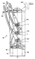
- These electrical cutoff means 700 placed in the housing 100 are preferably controlled mechanically using a rigid rod T which runs along the pole P from the base of the housing 100 and which ends at the bottom of the post with a manual or mechanized control system schematized under the reference Sc.
- the electrical switching means 700 are placed between two sections Li1 and Li2 of a medium power line or high voltage, by way of non-limiting example at 20,000 volts.
- phase conductors of a first section Li1 are connected respective T1 means passing through a first vertical face of the housing 100.
- the phase conductors of the second section Li2 are connected from symmetrically to respective T2 means crossing a second vertical face of the housing 100, opposite the first aforementioned.
- the system is completed by means suitable for limit any overvoltage at the phase lines.
- surge limiter means can be formed from surge arrester based on varistors, inserted for example between phase lines and neutral or the mass as shown diagrammatically under the reference Pa in FIG. 1.
- the cutting means electric proper 700 are interposed between the crossing means T1 and the crossing means T2.
- these switching means 700 comprise a set capable of rotation relative to a vertical axis O-O and comprising 3 pairs of knives or conductors 702 associated respectively with each phases, more precisely to clamps 402 provided respectively in end of each of the crossings T1, T2 corresponding to the various phases.
- each pair of knives 702 In a closed position of the device, each pair of knives 702 is electrically connected to clamps 402 and therefore to sections Li1 and Li2 of a given phase, via the means of crossing T1, T2.
- the knives 702 are pivoted in a position such that they are separated said crossing means T1, T2 and consequently sections of associated lines Li1 and Li2.
- step-down transformer tension located outside the housing 100, preferably at the top of the post P.
- the housing 100 is preferably made of folded and welded sheet metal.
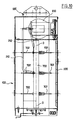
- the housing 100 has a polygon type section octagon. Thanks to this arrangement (in particular removal of any angle classic right on known boxes), we obtain a box with a optimal mechanical resistance.
- the housing 100 is formed of a waterproof structure and houses a neutral gas or self-extinguishing electric arc, for example SF6.
- the reference 210, 212 has illustrated the large-input transformer 200 conductors connected to high voltage phase sections and under reference 220 the conductors lower caliber output, corresponding to low voltage (240/300 Volts) and directed to the electronic cut-off management system, to the supply thereof, housed for example in an auxiliary box B in bottom of post.
- this minimum distance is preferably set at 61 mm.
- this distance can be reduced by placing sheaths electrically insulating heat shrink tubing, at least high voltage conductors, associated with transformer 200.
- the two conductors 200, 212 of large gauge essentially have a section horizontal for connection to transformer 200 and a section vertical ensuring the connection on the internal end to the housing 100 of a respective crossing T1.
- the housing 100 is equipped, on its upper wall, a valve 600 capable of opening automatically when the pressure at the interior of the housing 100 exceeds a determined threshold.
- An increase in pressure inside the housing 100 can be due in particular to a generation of gas resulting from a fault in operation of the device and / or untimely heating.
- the valve 600 can be the subject of numerous embodiments. It may, for example, be a box confining a circular membrane of stainless steel, for example with a thickness of the order of 2/10 th , resting against an O-ring seal. In normal operation, the housing is sealed by the O-ring. In the event of overpressure, the membrane can be moved away from the joint, or even be ejected, to allow evacuation of the gases.
- transformer voltage 200 is interposed between the electrical breaking means 700 and the valve 600, as seen in the attached figures.
- the transformer 200 forms a screen preventing any risk of projection of a part from the electrical switching means, towards the outside of the case, through the valve 600.
- valve 600 capable of constituting a mechanically weak zone on the upper wall of the case, it guarantees the protection of goods and people avoiding any risk of projection outside the case. he in this regard it should be noted that in certain circumstances, malfunctions of the switching means can lead to projections of molten parts at high temperature.
- the transformer 200 is preferably placed in a substantially central position of the housing 100, considered in its horizontal section, above the cutting means 700.
- T1, T2 we will now describe the structure of the means of crossing T1, T2, in accordance with the present invention. These means are on the one hand, preferably identical, between the T1 inlet crossings and the T2 output crossings and between phases on the other hand.
- each of these crossings T1, T2 includes a central electrical conductor 300, a rigid body of material electrically insulating 330 and an outer sheath with fins made of material silicone 360.
- the central electrical conductor 300 is made of all metal suitable known to those skilled in the art (aluminum for example). He introduces preferably a constant section. If applicable, this driver central electric 300 can be curved over part of its length, preferably external to the housing 100, to ensure connection to the sections of lines Li1 and Li2 optimally.
- the section of electrical conductor central 300 located on the outside of the housing 100 and adjacent respectively to one of the walls 110, 112 is straight and coaxial with the conductor section central electric 300 located inside the housing 100.
- the electrical connection on the ends of the conductor central electric 300, respectively inside the housing 100 (for cooperate with the mechanical cut-off means) and outside the housing 100 (to ensure connection to line sections Li1 and Li2) may be the subject of numerous variant embodiments.
- the end of the conductor 300 located inside the housing 100 has a tapped blind bore 302 for the connection of clamp 400 or equivalent means belonging to the electrical cut-off system.
- the end of the conductor 300 located outside the housing 100 can be flattened in the form of a blade 304 with 306 holes for electrical connection.
- the conductor 300 may, over part of his length inside the electrically insulating rigid body 330, have a zone equipped with a knurling 310 in order to ensure a connection satisfactory mechanics between the conductor 300 and the rigid body 330 which surrounds him.
- it may be a straight knurling. in steps of 1mm.
- the body electrically insulating 330 is made of rigid synthetic resin. It's about preferably an epoxy resin.
- this body 330 of epoxy resin can be overmolded on at least one frame 332 capable of forming a capacity in cooperation with conductor 300 to allow measurement voltage on each phase line.
- This voltage measurement device can also be supplemented by a current measurement system, based on committed toroids on the outside of each crossing T1 and / or T2 as illustrated on the Figure 6 under reference 334.
- the geometry of the rigid electrically insulating body 330 in epoxy resin can be the subject of many variants.
- the epoxy body 330 has an element 336 designed to be placed inside the housing 100 and which has a flat face 338 in the shape of a crown centered on the axis O-O of the conductor 300 and perpendicular to this axis O-O.
- This flat face 338 is intended for come to rest against the internal face of one of the walls 110, 112.
- element 336 has inserts 339, such as inserts threaded which open onto the bearing face 338 to ensure the fixing of a crossing T1 or T2 on said wall 110, 112 of the housing 100 using additional screwing means.
- Element 336 preferably has a cross-section convergent, i.e. reducing, away from the support phase 338 towards the inside of the housing 100.
- the element 336 illustrated in FIGS. 3 and 4 has a first section 3360 of cylindrical envelope of revolution adjacent to the support phase 338 and a tapered section 3364 tapered in direction of the free end of the body 330, connected together by a section intermediate 3362 in the shape of an O-ring.
- the axial length of element 336 can be of the order of 77.5 mm, and the internal diameter of the bearing surface 338 of the order of 70mm, while the external diameter of this bearing surface is of the order of 100mm.
- the element 340 of the body 330 located outside the housing 100 preferably has a symmetrical envelope of revolution around the axis O-O and tapered away from the surface 338.
- connection zones 343 and 345 defined between the pairs of adjacent sections 342/344 and 344/346 are preferably formed rounding, for example with an average radius of around 5mm, to avoid any peak effect.
- the mean diameter of the area of link 345 between the two sections 344 and 346 is of the order of 34mm.
- each crossing T1, T2 is completed by a 360 silicone sheath with fins.
- the 360 silicone sheath covers the entire element 340 of the body 330 outside the housing 100 and is extends on the conductor 300 clearly beyond the epoxy resin body 330.
- the sheath 360 does not extend inside the housing 100.
- the silicone sheath extends outside the body in epoxy resin 330 on conductor 300 over a distance of the order of 270mm.
- the fins 362 provided on the sheath 360 are formed of structures annulars generally perpendicular to the axis O-O. These fins can be the subject of numerous variant embodiments. They are part of preferably in an outer envelope of appreciably diameter constant to allow the passage of toroids 334.
- these fins 362 arise on the portion of the sheath 360 which covers the body 330, by having a progressively increasing height away from the wall 338. In this portion of sheath 360 the fins 362 have advantageously a pitch of the order of 25mm.
- the fins 362 In the sheath portion 260 located beyond the epoxy body 330, on the central conductor 300, the fins 362 have a larger diameter important, for example of the order of 840mm, and a lower pitch, for example of the order of 12.5mm (with where appropriate as seen on the Figure 3, an alternation of two diameters of fins 362).
- the minimum thickness of the 360 silicone sheath over most of its extent covering the conductor central 300 is 3mm, while the minimum thickness of this sheath silicone 360 on its extent covering sections 346, 344, and the portion adjacent section 342 is at least 5mm.
- the fins 362 extend at least over a length of 75mm on the portion directly covering the central conductor 300. It is thus provided at this level for example seven fins.
- a layer of a material ensuring an intimate adhesion between the respectively external faces of the body of epoxy material 330 and the adjacent internal surface of the sheath made of silicone material 360. This agent allows both to seal, strengthen the system on the plan climate (waterproof against pollution and rain) and perfect the behavior dielectric.
- crossing structure which has just been described allows in particular thanks to the geometry of the body 330 and to its fixing direct on the housing wall 100 to provide mechanical support for fixed contacts 400 participating in the cut.
- the housing 100 is provided with means for attaching the housing to the post P, comprising a reversible console 500 on the housing 100 to allow hanging selectively the housing 100 on the support P in two positions 180 ° symmetrical to each other, depending on whether the power source station is located on one side or the other of the housing.
- the console 500 comprises in the upper part an arch 510 in a general U shape, the cross section is complementary to that of the housing 100.
- the arch 510 includes a flat 512 core intended to rest against one of the secondary faces 114 or 116 of the housing 100 and two lateral branches 514, 516 orthogonal to the core 512 and intended to be joined against the outer surface of the main walls 110, 112 of the housing.
- branches 514, 516 are connected to the ends of the core 512 by oblique facets 513, 515 counterparts of the walls of connection 120, 122, 124, 126 of the housing.
- the core 512 is provided with holes 5120 for fixing on one of the secondary walls 114, 116.
- the lateral branches 514, 516 are provided with holes 5140, 5160 to ensure the fixing of the console 500 on the upper part of the main walls 110, 112 and secure the hooks, as illustrated under the reference 550 on the Figure 10 intended to ensure the suspension of the housing 100 at the top of the post P.
- the lateral branches 514, 516 can also be used for fixing means for supporting line link sections as shown schematically under the reference 560 in FIG. 6.
- the console 500 also has a support leg 520 formed a generally straight blade that projects downward from the middle of the core 512.
- this leg 520 has 522 structures folded outwards, i.e. opposite the branches 514, 516, intended to rest against the P post to provide support vertical of the housing 100.
- the console 500 is preferably made of stainless steel.
Landscapes
- Power Engineering (AREA)
- Engineering & Computer Science (AREA)
- Electronic Switches (AREA)
- Housings And Mounting Of Transformers (AREA)
- Insulators (AREA)
- Patch Boards (AREA)
- Connector Housings Or Holding Contact Members (AREA)
- Processing Of Stones Or Stones Resemblance Materials (AREA)
- Mechanical Treatment Of Semiconductor (AREA)
- Casings For Electric Apparatus (AREA)
- Gas-Insulated Switchgears (AREA)
- Treatments Of Macromolecular Shaped Articles (AREA)
- Organic Insulating Materials (AREA)
Applications Claiming Priority (2)
| Application Number | Priority Date | Filing Date | Title |
|---|---|---|---|
| FR9815435A FR2786944B1 (fr) | 1998-12-07 | 1998-12-07 | Perfectionnements aux dispositifs de coupure electrique pour moyenne et haute tension |
| FR9815435 | 1998-12-07 |
Publications (3)
| Publication Number | Publication Date |
|---|---|
| EP1018756A2 true EP1018756A2 (de) | 2000-07-12 |
| EP1018756A3 EP1018756A3 (de) | 2000-11-15 |
| EP1018756B1 EP1018756B1 (de) | 2003-03-26 |
Family
ID=9533678
Family Applications (1)
| Application Number | Title | Priority Date | Filing Date |
|---|---|---|---|
| EP99403046A Expired - Lifetime EP1018756B1 (de) | 1998-12-07 | 1999-12-07 | Mittle oder Hochspannungsschaltvorrichtung |
Country Status (6)
| Country | Link |
|---|---|
| EP (1) | EP1018756B1 (de) |
| AT (1) | ATE235738T1 (de) |
| DE (1) | DE69906238T2 (de) |
| ES (1) | ES2190183T3 (de) |
| FR (1) | FR2786944B1 (de) |
| PT (1) | PT1018756E (de) |
Cited By (1)
| Publication number | Priority date | Publication date | Assignee | Title |
|---|---|---|---|---|
| EP1865517A2 (de) * | 2006-06-05 | 2007-12-12 | COMEM S.p.A. | Durchführungsisolator für elektrische Wandler |
Families Citing this family (2)
| Publication number | Priority date | Publication date | Assignee | Title |
|---|---|---|---|---|
| CN109861118B (zh) * | 2018-12-21 | 2020-04-07 | 广东东捷实业有限公司 | 一种户外紧凑型智能变电站 |
| EP3745547B1 (de) | 2019-05-31 | 2023-02-15 | Hitachi Energy Switzerland AG | Anordnung mit einer turmmontierte hochspannungs-schaltanlage und einem hochspannungs-turm |
Family Cites Families (6)
| Publication number | Priority date | Publication date | Assignee | Title |
|---|---|---|---|---|
| JP2549170B2 (ja) * | 1989-04-24 | 1996-10-30 | 株式会社日立製作所 | 柱上用開閉器 |
| FR2651603B1 (fr) * | 1989-09-07 | 1991-11-08 | Merlin Gerin | Mecanisme de commande d'un interrupteur multipolaire a haute tension. |
| GB2252671B (en) * | 1991-02-07 | 1994-08-03 | Long & Crawford Limited | High power switching arrangement |
| DE29507391U1 (de) * | 1995-04-28 | 1995-06-29 | Siemens AG, 80333 München | An einem Tragmast montierbare mehrpolige Schalteinheit |
| FR2735898B1 (fr) * | 1995-06-20 | 1997-08-01 | Gec Alsthom T & D Sa | Procede de fabrication d'un isolateur en materiau composite |
| FR2747500B1 (fr) * | 1996-04-12 | 1998-06-26 | Soule Materiel Electr | Parafoudre perfectionne a base de varistances |
-
1998
- 1998-12-07 FR FR9815435A patent/FR2786944B1/fr not_active Expired - Fee Related
-
1999
- 1999-12-07 ES ES99403046T patent/ES2190183T3/es not_active Expired - Lifetime
- 1999-12-07 DE DE69906238T patent/DE69906238T2/de not_active Expired - Lifetime
- 1999-12-07 PT PT99403046T patent/PT1018756E/pt unknown
- 1999-12-07 EP EP99403046A patent/EP1018756B1/de not_active Expired - Lifetime
- 1999-12-07 AT AT99403046T patent/ATE235738T1/de not_active IP Right Cessation
Cited By (1)
| Publication number | Priority date | Publication date | Assignee | Title |
|---|---|---|---|---|
| EP1865517A2 (de) * | 2006-06-05 | 2007-12-12 | COMEM S.p.A. | Durchführungsisolator für elektrische Wandler |
Also Published As
| Publication number | Publication date |
|---|---|
| DE69906238D1 (de) | 2003-04-30 |
| PT1018756E (pt) | 2003-07-31 |
| EP1018756A3 (de) | 2000-11-15 |
| ES2190183T3 (es) | 2003-07-16 |
| DE69906238T2 (de) | 2003-10-30 |
| FR2786944B1 (fr) | 2003-09-19 |
| FR2786944A1 (fr) | 2000-06-09 |
| ATE235738T1 (de) | 2003-04-15 |
| EP1018756B1 (de) | 2003-03-26 |
Similar Documents
| Publication | Publication Date | Title |
|---|---|---|
| CA2138634C (fr) | Ligne a haute tension a isolation gazeuse pour longue distance | |
| FR2752089A1 (fr) | Generateur electrochimique cylindrique | |
| FR2574589A1 (fr) | Dispositif de mise en court-circuit exterieur de faible encombrement | |
| EP1018756B1 (de) | Mittle oder Hochspannungsschaltvorrichtung | |
| FR2668851A1 (fr) | Interrupteur rotatif multipolaire. | |
| EP1009002A1 (de) | Mittel-und Hochspannungsschaltanlage | |
| FR2834138A1 (fr) | Element de poste blinde articule au sol | |
| EP0923785A1 (de) | Hochspannungs-/niederspannungstransformator mit thermoplastischer trockenisolation | |
| FR2811134A1 (fr) | Traversee de haute tension en plein air et appareil de commutation a haute tension equipe d'une telle traversee | |
| EP0393182B1 (de) | Schutzanordnung für elektrische leistungswiderstände und anti-überdrucksystem | |
| FR2786945A1 (fr) | Dispositif de coupure electrique perfectionne pour moyenne et haute tension | |
| CH621653A5 (de) | ||
| FR2996353A1 (fr) | Boitier a fusible pour moteur electrique, notamment de vehicule automobile | |
| EP2633538B1 (de) | Elektrische vorrichtung in einem metallgehäuse, besagte vorrichtung mit mindestens einer abschirmhaube zur sicherstellung von konvektivem austausch | |
| CA2286416C (fr) | Montage de resistance de fermeture pour appareillage electrique a haute tension | |
| CA1162260A (fr) | Dispositif de securite contre les arcs electriques | |
| EP1612823B1 (de) | Passive Kühlvorrichtung für ein elektrisches Gerät und elektrisches Gerät mit einer solchen Vorrichtung | |
| EP1337018A1 (de) | Gasisolierte Stromdurchführung | |
| FR2745960A1 (fr) | Dispositif de raccordement electrique permettant de connecter plusieurs cables de derivation a partir d'un cable d'arrivee | |
| FR2537791A1 (fr) | Dispositif de derivation pour cables electriques | |
| FR2736461A1 (fr) | Traversee dielectriquement etanche | |
| FR2566101A1 (fr) | Chauffe-eau electrique | |
| EP1225672B1 (de) | Gerät zur Kontrolle eines internen Fehlerlichtbogens für einen Anschlussmodul in einer gasisolierten Hochspannungsleitung | |
| FR2854001A1 (fr) | Traversee isolante pour interrupteur de ligne electrique a moyenne tension | |
| FR2597664A1 (fr) | Dispositif de connexion electrique du type a perforation d'isolant |
Legal Events
| Date | Code | Title | Description |
|---|---|---|---|
| PUAI | Public reference made under article 153(3) epc to a published international application that has entered the european phase |
Free format text: ORIGINAL CODE: 0009012 |
|
| AK | Designated contracting states |
Kind code of ref document: A2 Designated state(s): AT BE CH CY DE DK ES FI FR GB GR IE IT LI LU MC NL PT SE |
|
| AX | Request for extension of the european patent |
Free format text: AL;LT;LV;MK;RO;SI |
|
| PUAL | Search report despatched |
Free format text: ORIGINAL CODE: 0009013 |
|
| AK | Designated contracting states |
Kind code of ref document: A3 Designated state(s): AT BE CH CY DE DK ES FI FR GB GR IE IT LI LU MC NL PT SE |
|
| AX | Request for extension of the european patent |
Free format text: AL;LT;LV;MK;RO;SI |
|
| RIC1 | Information provided on ipc code assigned before grant |
Free format text: 7H 01H 33/02 A, 7H 02B 13/025 B |
|
| 17P | Request for examination filed |
Effective date: 20010430 |
|
| AKX | Designation fees paid |
Free format text: AT BE CH CY DE DK ES FI FR GB GR IE IT LI LU MC NL PT SE |
|
| GRAG | Despatch of communication of intention to grant |
Free format text: ORIGINAL CODE: EPIDOS AGRA |
|
| 17Q | First examination report despatched |
Effective date: 20011213 |
|
| GRAG | Despatch of communication of intention to grant |
Free format text: ORIGINAL CODE: EPIDOS AGRA |
|
| GRAH | Despatch of communication of intention to grant a patent |
Free format text: ORIGINAL CODE: EPIDOS IGRA |
|
| GRAH | Despatch of communication of intention to grant a patent |
Free format text: ORIGINAL CODE: EPIDOS IGRA |
|
| GRAA | (expected) grant |
Free format text: ORIGINAL CODE: 0009210 |
|
| AK | Designated contracting states |
Designated state(s): AT BE CH CY DE DK ES FI FR GB GR IE IT LI LU MC NL PT SE |
|
| PG25 | Lapsed in a contracting state [announced via postgrant information from national office to epo] |
Ref country code: NL Free format text: LAPSE BECAUSE OF FAILURE TO SUBMIT A TRANSLATION OF THE DESCRIPTION OR TO PAY THE FEE WITHIN THE PRESCRIBED TIME-LIMIT Effective date: 20030326 Ref country code: FI Free format text: LAPSE BECAUSE OF FAILURE TO SUBMIT A TRANSLATION OF THE DESCRIPTION OR TO PAY THE FEE WITHIN THE PRESCRIBED TIME-LIMIT Effective date: 20030326 Ref country code: AT Free format text: LAPSE BECAUSE OF FAILURE TO SUBMIT A TRANSLATION OF THE DESCRIPTION OR TO PAY THE FEE WITHIN THE PRESCRIBED TIME-LIMIT Effective date: 20030326 |
|
| REG | Reference to a national code |
Ref country code: GB Ref legal event code: FG4D Free format text: NOT ENGLISH |
|
| REG | Reference to a national code |
Ref country code: CH Ref legal event code: EP |
|
| REG | Reference to a national code |
Ref country code: SE Ref legal event code: TRGR |
|
| GBT | Gb: translation of ep patent filed (gb section 77(6)(a)/1977) |
Effective date: 20030401 |
|
| REF | Corresponds to: |
Ref document number: 69906238 Country of ref document: DE Date of ref document: 20030430 Kind code of ref document: P |
|
| REG | Reference to a national code |
Ref country code: IE Ref legal event code: FG4D Free format text: FRENCH |
|
| PG25 | Lapsed in a contracting state [announced via postgrant information from national office to epo] |
Ref country code: DK Free format text: LAPSE BECAUSE OF FAILURE TO SUBMIT A TRANSLATION OF THE DESCRIPTION OR TO PAY THE FEE WITHIN THE PRESCRIBED TIME-LIMIT Effective date: 20030626 |
|
| REG | Reference to a national code |
Ref country code: ES Ref legal event code: FG2A Ref document number: 2190183 Country of ref document: ES Kind code of ref document: T3 Ref country code: GR Ref legal event code: EP Ref document number: 20030402166 Country of ref document: GR |
|
| NLV1 | Nl: lapsed or annulled due to failure to fulfill the requirements of art. 29p and 29m of the patents act | ||
| PG25 | Lapsed in a contracting state [announced via postgrant information from national office to epo] |
Ref country code: LU Free format text: LAPSE BECAUSE OF NON-PAYMENT OF DUE FEES Effective date: 20031207 Ref country code: CY Free format text: LAPSE BECAUSE OF FAILURE TO SUBMIT A TRANSLATION OF THE DESCRIPTION OR TO PAY THE FEE WITHIN THE PRESCRIBED TIME-LIMIT Effective date: 20031207 |
|
| PG25 | Lapsed in a contracting state [announced via postgrant information from national office to epo] |
Ref country code: MC Free format text: LAPSE BECAUSE OF NON-PAYMENT OF DUE FEES Effective date: 20031231 Ref country code: LI Free format text: LAPSE BECAUSE OF NON-PAYMENT OF DUE FEES Effective date: 20031231 Ref country code: CH Free format text: LAPSE BECAUSE OF NON-PAYMENT OF DUE FEES Effective date: 20031231 Ref country code: BE Free format text: LAPSE BECAUSE OF NON-PAYMENT OF DUE FEES Effective date: 20031231 |
|
| PLBE | No opposition filed within time limit |
Free format text: ORIGINAL CODE: 0009261 |
|
| STAA | Information on the status of an ep patent application or granted ep patent |
Free format text: STATUS: NO OPPOSITION FILED WITHIN TIME LIMIT |
|
| 26N | No opposition filed |
Effective date: 20031230 |
|
| BERE | Be: lapsed |
Owner name: *SOULE MATERIEL ELECTRIQUE Effective date: 20031231 |
|
| REG | Reference to a national code |
Ref country code: CH Ref legal event code: PL |
|
| REG | Reference to a national code |
Ref country code: FR Ref legal event code: TP |
|
| REG | Reference to a national code |
Ref country code: FR Ref legal event code: PLFP Year of fee payment: 17 |
|
| REG | Reference to a national code |
Ref country code: FR Ref legal event code: PLFP Year of fee payment: 18 |
|
| REG | Reference to a national code |
Ref country code: FR Ref legal event code: PLFP Year of fee payment: 19 |
|
| PGFP | Annual fee paid to national office [announced via postgrant information from national office to epo] |
Ref country code: DE Payment date: 20181211 Year of fee payment: 20 Ref country code: GR Payment date: 20181120 Year of fee payment: 20 Ref country code: IE Payment date: 20181127 Year of fee payment: 20 Ref country code: SE Payment date: 20181213 Year of fee payment: 20 Ref country code: PT Payment date: 20181116 Year of fee payment: 20 |
|
| PGFP | Annual fee paid to national office [announced via postgrant information from national office to epo] |
Ref country code: FR Payment date: 20181207 Year of fee payment: 20 Ref country code: IT Payment date: 20181207 Year of fee payment: 20 Ref country code: GB Payment date: 20181218 Year of fee payment: 20 |
|
| PGFP | Annual fee paid to national office [announced via postgrant information from national office to epo] |
Ref country code: ES Payment date: 20190125 Year of fee payment: 20 |
|
| REG | Reference to a national code |
Ref country code: DE Ref legal event code: R071 Ref document number: 69906238 Country of ref document: DE |
|
| REG | Reference to a national code |
Ref country code: GB Ref legal event code: PE20 Expiry date: 20191206 |
|
| REG | Reference to a national code |
Ref country code: SE Ref legal event code: EUG |
|
| PG25 | Lapsed in a contracting state [announced via postgrant information from national office to epo] |
Ref country code: PT Free format text: LAPSE BECAUSE OF EXPIRATION OF PROTECTION Effective date: 20191219 Ref country code: GB Free format text: LAPSE BECAUSE OF EXPIRATION OF PROTECTION Effective date: 20191206 |
|
| REG | Reference to a national code |
Ref country code: IE Ref legal event code: MK9A |
|
| PG25 | Lapsed in a contracting state [announced via postgrant information from national office to epo] |
Ref country code: IE Free format text: LAPSE BECAUSE OF EXPIRATION OF PROTECTION Effective date: 20191207 |
|
| REG | Reference to a national code |
Ref country code: ES Ref legal event code: FD2A Effective date: 20201110 |
|
| PG25 | Lapsed in a contracting state [announced via postgrant information from national office to epo] |
Ref country code: ES Free format text: LAPSE BECAUSE OF EXPIRATION OF PROTECTION Effective date: 20191208 |