EP3745547B1 - Anordnung mit einer turmmontierte hochspannungs-schaltanlage und einem hochspannungs-turm - Google Patents
Anordnung mit einer turmmontierte hochspannungs-schaltanlage und einem hochspannungs-turm Download PDFInfo
- Publication number
- EP3745547B1 EP3745547B1 EP19177767.1A EP19177767A EP3745547B1 EP 3745547 B1 EP3745547 B1 EP 3745547B1 EP 19177767 A EP19177767 A EP 19177767A EP 3745547 B1 EP3745547 B1 EP 3745547B1
- Authority
- EP
- European Patent Office
- Prior art keywords
- combined
- high voltage
- disconnection
- interruption
- disconnecting
- Prior art date
- Legal status (The legal status is an assumption and is not a legal conclusion. Google has not performed a legal analysis and makes no representation as to the accuracy of the status listed.)
- Active
Links
Images






Classifications
-
- H—ELECTRICITY
- H02—GENERATION; CONVERSION OR DISTRIBUTION OF ELECTRIC POWER
- H02B—BOARDS, SUBSTATIONS OR SWITCHING ARRANGEMENTS FOR THE SUPPLY OR DISTRIBUTION OF ELECTRIC POWER
- H02B13/00—Arrangement of switchgear in which switches are enclosed in, or structurally associated with, a casing, e.g. cubicle
- H02B13/02—Arrangement of switchgear in which switches are enclosed in, or structurally associated with, a casing, e.g. cubicle with metal casing
- H02B13/035—Gas-insulated switchgear
- H02B13/075—Earthing arrangements
-
- H—ELECTRICITY
- H02—GENERATION; CONVERSION OR DISTRIBUTION OF ELECTRIC POWER
- H02B—BOARDS, SUBSTATIONS OR SWITCHING ARRANGEMENTS FOR THE SUPPLY OR DISTRIBUTION OF ELECTRIC POWER
- H02B3/00—Apparatus specially adapted for the manufacture, assembly, or maintenance of boards or switchgear
-
- H—ELECTRICITY
- H02—GENERATION; CONVERSION OR DISTRIBUTION OF ELECTRIC POWER
- H02B—BOARDS, SUBSTATIONS OR SWITCHING ARRANGEMENTS FOR THE SUPPLY OR DISTRIBUTION OF ELECTRIC POWER
- H02B5/00—Non-enclosed substations; Substations with enclosed and non-enclosed equipment
- H02B5/02—Non-enclosed substations; Substations with enclosed and non-enclosed equipment mounted on pole, e.g. pole transformer substation
-
- H—ELECTRICITY
- H02—GENERATION; CONVERSION OR DISTRIBUTION OF ELECTRIC POWER
- H02B—BOARDS, SUBSTATIONS OR SWITCHING ARRANGEMENTS FOR THE SUPPLY OR DISTRIBUTION OF ELECTRIC POWER
- H02B5/00—Non-enclosed substations; Substations with enclosed and non-enclosed equipment
- H02B5/06—Non-enclosed substations; Substations with enclosed and non-enclosed equipment gas-insulated
-
- H—ELECTRICITY
- H02—GENERATION; CONVERSION OR DISTRIBUTION OF ELECTRIC POWER
- H02B—BOARDS, SUBSTATIONS OR SWITCHING ARRANGEMENTS FOR THE SUPPLY OR DISTRIBUTION OF ELECTRIC POWER
- H02B13/00—Arrangement of switchgear in which switches are enclosed in, or structurally associated with, a casing, e.g. cubicle
- H02B13/02—Arrangement of switchgear in which switches are enclosed in, or structurally associated with, a casing, e.g. cubicle with metal casing
- H02B13/035—Gas-insulated switchgear
Definitions
- the present invention relates to an arrangement comprising a tower mounted gas insulated switchgear and a high voltage transmission tower having improved functions and characteristics. It is well known in the art that along the path of a power grid there are provided several electric substations for transmitting and distributing electricity from a power generating source to loads and users connected to the feeding grid; these substations may be configured according to different layouts depending on the applications, and are realized by using a number of electric components, such as disconnectors, circuit breakers, instrument transformers, control systems and similar devices.
- electric substations are realized by using several components which are structurally independent and suitably connected to each other and to the power line when assembling in order to obtain the required layout and to perform each a respective dedicated function;
- these traditional solutions have presented some drawbacks in practical use, mainly due to the large number of components required, even for providing a minimal configuration, and to their structural and functional separation. Indeed, these aspects result in heavy maintenance requirements for each and any of the components used, and to a considerable increase of the overall dimensions of the substation, with a consequent negative impact on installation and maintenance costs, as well as on environmental impact.
- these new devices comprise an external casing on which there are mounted a number of bushings, e.g. two or three bushings, each containing a corresponding electric terminal for input/output connections with a power line and/or other elements of the substation; inside the casing there are normally provided one or more disconnection units and one or more interruption units, which are electrically connected to each other and to the electric terminals, in such a way that electrical disconnection and/or circuit breaker maneuvers are performed in a coordinated way.
- a number of bushings e.g. two or three bushings, each containing a corresponding electric terminal for input/output connections with a power line and/or other elements of the substation
- inside the casing there are normally provided one or more disconnection units and one or more interruption units, which are electrically connected to each other and to the electric terminals, in such a way that electrical disconnection and/or circuit breaker maneuvers are performed in a coordinated way.
- a dedicated area is in general needed for the installation of the high voltage switchgear and in many cases the land needed for the equipment requires a long and expensive process to get the approval from the local authorities. It may also happen frequently that the land needed is not available due, e.g., to permissions denied (for instance in urbanized areas) or to insufficient space (for instance in rural areas, or in areas morphologically not suitable such us mountains). It can therefore happen that utilities are forced to stop the project.
- WO 0150487 A1 describes a disconnector for high-voltage overhead power lines, whose particularity consists of the fact that it comprises: a sealed enclosure which contains a dielectric fluid and inside which a plurality of fixed contacts and a plurality of moving contacts are accommodated, said moving contacts being able to mutually couple/uncouple with respect to the corresponding fixed contacts; an actuation rod which is connected to said moving contacts and lies longitudinally within said enclosure; said moving contacts being moved on a plane which is perpendicular to the longitudinal axis of the enclosure by means of a rotary motion of said actuation rod; a remote-controlled motorized actuation unit which is operatively connected to said actuation rod; and supporting means for installation on a pylon of a high-voltage overhead power line.
- FR 1045034 A describes a shunt switchgear making it possible to isolate a device from a high voltage electrical line which supplies it, without interrupting the line, comprising, on the one hand, two breaking devices arranged respectively upstream and downstream of the device to be isolated, and on the other hand, a rotary device for bypassing the assembly formed by said device and the two switching devices.
- ABB's online news item ABB switchgear provides safe and reliable power to busy streets of Bangkok [19-12-2017]" discloses a high voltage gas insulated switchgear with interruption and disconnection capabilities which is mounted on a gantry platform supported between two concrete poles.
- FR2786944 shows another tower-mounted high voltage gas insulated switchgear.
- the present disclosure is aimed at providing an arrangement comprising a high voltage gas insulated switchgear and a high voltage transmission tower which allows overcoming at least some of the above-mentioned shortcomings.
- the present invention is aimed at providing an arrangement that would avoid the need of requesting approval from local authorities.
- the present invention is aimed at providing an arrangement which would not be affected for its installation by the morphology of the land Moreover, the present invention is aimed at providing an arrangement in which the environmental impact is minimized or eliminated.
- the present invention is aimed at providing an arrangement which is easily adaptable according to needs of the utilities Also, the present invention is aimed at providing an arrangement that is reliable and relatively easy to be manufactured out and at competitive costs.
- the present invention relates to an arrangement which comprises a supporting structure connected to the lattice structure of a high voltage transmission tower, a first and a second gas-insulated combined interruption and disconnection modules respectively comprising, for each phase, a first and a second combined interruption and disconnection units.
- Each of said first and second combined interruption and disconnection units comprises a first and a second gas-tight casing developing along corresponding first and second reference axis, each casing housing: at least a first terminal for input/output connections; a first combined disconnecting and earthing switch having a first fixed contact operatively coupled to said first terminal, a second fixed contact at ground potential and a first movable contact operatively couplable to said first and second fixed contacts for disconnecting and earthing operations; a fast earthing switch interposed between said first fixed contact and said first terminal; a circuit breaker unit electrically connected to said first movable contact of said first combined disconnecting and earthing switch and to a second combined disconnecting and earthing switch; said second combined disconnecting and earthing switch having a third fixed contact operatively coupled to a second terminal for input/output connections, a fourth fixed contact at ground potential and a second movable contact operatively couplable to said third and fourth fixed contacts for disconnecting and earthing operations and electrically connected to said circuit breaker unit.
- Said first terminal of said first combined interruption and disconnection unit is electrically connected to a first electrical line
- said first terminal of said second interruption and disconnection unit is electrically connected to a second electrical line
- the second terminals of said first and second combined interruption and disconnection units are electrically coupled to each other.
- the high voltage gas-insulated switchgear is mounted on said supporting structure within the lattice structure of said high voltage transmission tower, the first and second reference axis of said first and second casings being aligned in the same direction.
- the arrangement as disclosed herein allows avoiding, or at least greatly reducing, the above-mentioned problems.
- the proposed solution consists of placing the high voltage gas-insulated switchgear in the tower of the overhead lines. This solution avoids the request of approval from local authorities as there is no occupation of new land and results in a faster and cheaper solution for the customer.
- the high voltage gas-insulated switchgear can be fully assembled and tested in the factory and then transported at site. Once mounted in the tower, possibly together with the local control cubicle, the high voltage gas-insulated switchgear is ready to be energized. Monitoring and self-diagnostics systems integrated in the equipment allow a remote control of the status of the equipment itself further increasing the reliability of the solution.
- a typical configuration can be a 3 bays system (in-out bays plus user bay) to be mounted in the tower at different height from the ground depending on customer requests. As mentioned before the system must stay in the tower footprint so to avoid the need of permission.
- said first and second combined interruption and disconnection modules are positioned at a height within the lattice structure of said high voltage transmission tower.
- said first and second combined interruption and disconnection modules can also be positioned within the lattice structure of said high voltage transmission tower in correspondence of its base.
- said first and second reference axis of said first and second casings are aligned along a common axis.
- said first and second reference axis of said first and second casings can be parallel to each other.
- the configuration is a 3 bays system (in-out bays plus user bay); in such a case, the tower mounted high voltage switchgear further comprises a third gas-insulated combined interruption and disconnection module having a first terminal operatively connectable to an end user, and a second terminal electrically interposed between and connected to said first and second combined interruption and disconnection modules.
- said third combined interruption and disconnection module comprises, for each phase, a third combined interruption and disconnection unit which in turn comprises a third casing developing along a third reference axis and housing: at least a first terminal operatively connectable to an end user; a first combined disconnecting and earthing switch having a first fixed contact operatively coupled to said first terminal, a second fixed contact at ground potential and a first movable contact operatively couplable to said first and second fixed contacts for disconnecting and earthing operations; a fast earthing switch interposed between said first fixed contact and said first terminal; a circuit breaker unit electrically connected to said first movable contact of said first combined disconnecting and earthing switch and to a second combined disconnecting and earthing switch; said second combined disconnecting and earthing switch having a third fixed contact operatively coupled to a second terminal electrically interposed between and connected to said first and second combined interruption and disconnection modules, a fourth fixed contact at ground potential and a second movable contact operatively couplable to said third and fourth
- the tower mounted high voltage switchgear can have different configurations and layouts according to the needs.
- the third combined interruption and disconnection module can be positioned within the lattice structure of said high voltage transmission tower at the same height of said first and second combined interruption and disconnection modules.
- said third combined interruption and disconnection module can be positioned within the lattice structure of said high voltage transmission tower at a different height with respect to said first and second combined interruption and disconnection modules.
- said first, second and third reference axis of said first, second and third casings are parallel to each other.
- said first and second reference axis of said first and second casings are aligned along a common axis, while said third reference axis of said third casing is substantially perpendicular to said first and second reference axis.
- said third combined interruption and disconnection module can be conveniently positioned within the lattice structure of said high voltage transmission tower at a different height with respect to said first and second combined interruption and disconnection modules.
- said first and second reference axis of said first and second casings are substantially horizontal.
- the third reference axis of said third casing can be substantially vertical.
- said first, second and third reference axis of said first, second and third casings are substantially vertical.
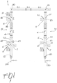
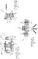
- a tower mounted high voltage switchgear designated with the reference numeral 1 in its more general definition comprises a supporting structure 10 which is connected to the lattice structure 11 of a high voltage transmission tower 12.
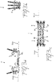
- the high voltage switchgear 1 comprises a first 2 and a second 3 combined interruption and disconnection modules respectively comprising, for each phase, a first 21 and a second 31 combined interruption and disconnection units.
- Each of said first 21 and second 31 combined interruption and disconnection units comprises a first 22 and a second 32 gas-tight casing developing along corresponding first 220 and second 320 reference axis.
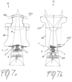
- Said casing 22 and 32 each houses at least a first terminal 50 for input/output connections and a first combined disconnecting and earthing switch 6.
- the combined disconnecting and earthing switch 6 can be of known type and typically has a first fixed contact 61 which is operatively coupled to said first terminal 50, a second fixed 62 contact at ground potential, and a first movable contact 63 which is operatively couplable to said first 61 and second 62 fixed contacts for disconnecting and earthing operations according to known principles.
- each of said casing 22 and 32 there is also positioned a fast earthing switch 7 which is interposed between said first fixed contact 61 and said first terminal 50.
- the fast earthing switch 7 can be of known type and will not be described in further details.
- a circuit breaker unit 4 is also positioned inside each casing 22 and 32 and is electrically connected to the first movable contact 63 of said first combined disconnecting and earthing switch 6 and to a corresponding second combined disconnecting and earthing switch 8, which is also housed inside each of said casings 22 and 32.
- Said second combined disconnecting and earthing switch 8 can be of known type and typically has having a third fixed contact 81 which is operatively coupled to a second terminal 90 for input/output connections, a fourth fixed contact 82 at ground potential, and a second movable contact 83 which is electrically connected to said circuit breaker unit 4 and operatively couplable to said third 81 and fourth 82 fixed contacts for disconnecting and earthing operations according to known principles.
- said first 21 and second 31 combined interruption and disconnection units are structurally and functionally identical to each other.
- the first terminal 50 of said first combined interruption and disconnection unit 21 is electrically connected to a first electrical line 510, while the first terminal 50 of said second interruption and disconnection unit 31 is electrically connected to a second electrical line 520. Moreover, the second terminals 90 of said first 21 and second 31 combined interruption and disconnection units being electrically coupled to each other, thereby realizing a typical two-bays in-out configuration.
- the high voltage switchgear 1 is mounted on said supporting structure 10 within the lattice structure 11 of said high voltage transmission tower 12, thereby avoiding any land occupation outside the footprint of tower 12 itself.
- a further feature of the tower mounted high voltage switchgear is given by the fact that the first 220 and second 320 reference axis of said first 22 and second 32 casings are aligned in the same direction, thereby achieving a very compact structure that can be housed within the lattice structure 11 of the high voltage transmission tower 12.
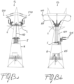
- said first 2 and second 3 combined interruption and disconnection modules can be positioned at different heights within the lattice structure 11 of said high voltage transmission tower 12.
- said first 2 and second 3 combined interruption and disconnection modules can be positioned within the lattice structure 11 of said high voltage transmission tower 12 in correspondence of its base 121.
- a control cubicle 85 can be also mounted at different heights within the lattice structure 11 of said high voltage transmission tower 12.
- said first 220 and second 320 reference axis of said first 22 and second 32 casings are aligned along a common axis, that is preferably substantially horizontal.
- said first 220 and second 320 reference axis of said first 22 and second 32 casings are parallel to each other, preferably in a substantially vertical orientation.
- the layout can be adapted to the available space within the lattice structure 11 of the high voltage transmission tower 12, by maintaining the modules aligned on a same horizontal plane or on different parallel vertical planes.
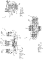
- the configuration can be a 3 bays system (in-out bays plus user bay).
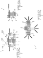
- the tower mounted high voltage switchgear 1 comprises - in addition to the first 2 and second 3 combined interruption and disconnection modules - also a third combined interruption and disconnection module 5 which has a first terminal 50 operatively connectable to an end user, and a second terminal 90 which is electrically interposed between and connected to said first 2 and second 3 combined interruption and disconnection modules.
- said third combined interruption and disconnection module 5 comprises, for each phase, a third combined interruption and disconnection unit 51, which in turn comprises a third casing 52 developing along a third reference axis 530.
- Said casing 52 houses at least a first terminal 50 which is operatively connectable to an end user and a first combined disconnecting and earthing switch 6.
- the combined disconnecting and earthing switch 6 can be of known type and typically has a first fixed contact 61 which is operatively coupled to said first terminal 50, a second fixed 62 contact at ground potential, and a first movable contact 63 which is operatively couplable to said first 61 and second 62 fixed contacts for disconnecting and earthing operations according to known principles.
- a fast earthing switch 7 which is interposed between said first fixed contact 61 and said first terminal 50.
- the fast earthing switch 7 can be of known type and will not be described in further details.
- a circuit breaker unit 4 is also positioned inside said casing 52 and is electrically connected to the first movable contact 63 of said first combined disconnecting and earthing switch 6 and to a corresponding second combined disconnecting and earthing switch 8, which is also housed inside said casing 52.
- Said second combined disconnecting and earthing switch 8 can be of known type and typically has having a third fixed contact 81 which is operatively coupled to a second terminal 90 electrically interposed between and connected to said first 2 and second 3 combined interruption and disconnection modules, a fourth fixed contact 82 at ground potential, and a second movable contact 83 which is electrically connected to said circuit breaker unit 4 and operatively couplable to said third 81 and fourth 82 fixed contacts for disconnecting and earthing operations according to known principles.
- said third combined interruption and disconnection module 5 is positioned within the lattice structure 11 of said high voltage transmission tower 12 at the same height of said first 2 and second 3 combined interruption and disconnection modules.
- said third combined interruption and disconnection module 5 is positioned within the lattice structure 11 of said high voltage transmission tower 12 at a different height with respect to said first 2 and second 3 combined interruption and disconnection modules.
- said said first 220, second 320 and third 530 reference axis of said first 22, second 32 and third 52 casings are parallel to each other.
- said first 220 and second 320 reference axis of said first 22 and second 32 casings are aligned along a common axis while said third reference axis 530 of said third casing 52 is substantially perpendicular to said first 220 and second 320 reference axis.
- the third combined interruption and disconnection module 5 is advantageously positioned within the lattice structure 11 of said high voltage transmission tower 12 at a different height with respect to said first 2 and second 3 combined interruption and disconnection modules.
- the switchgear can be realized according to the needs, having as only constrain to remain within the footprint of the tower.
- the first 220 and second 320 reference axis of said first 22 and second 32 casings are substantially horizontal.
- first 220, second 320 and third 430 reference axis of said first 22, second 32 and third casings 52 are substantially vertical.
- connections with the lines 510, 521 and with the end user(s) 515 can be made with conductors 151, insulated cables 152, or insulated ducts 150.
Landscapes
- Engineering & Computer Science (AREA)
- Power Engineering (AREA)
- Manufacturing & Machinery (AREA)
- Gas-Insulated Switchgears (AREA)
Claims (14)
- Anordnung, eine mastmontierte, gasisolierte Hochspannungs-Schaltanlage (1) und einen Hochspannungs-Fernleitungsmast (12) umfassend, wobei die mastmontierte, gasisolierte Hochspannungs-Schaltanlage (1) eine Stützstruktur (10) umfasst, die mit der Gitterstruktur (11) des Hochspannungs-Fernleitungsmasts (12) verbunden ist, ein erstes (2) und ein zweites (3) gasisoliertes kombiniertes Unterbrechungs- und Trennungsmodul, die für jede Phase eine erste (21) beziehungsweise eine zweite (31) kombinierte Unterbrechungs- und Trennungseinheit umfassen, wobei die erste (21) und die zweite (31) kombinierte Unterbrechungs- und Trennungseinheit jeweils ein erstes (22) und ein zweites (32) gasdichtes Gehäuse umfassen, die sich entlang einer entsprechenden ersten (220) und zweiten (320) Bezugsachse erstrecken, und jeweils Folgendes beherbergen: mindestens einen ersten Anschluss (50) für die Verbindung mit Eingang/Ausgang, einen ersten kombinierten Trennungs- und Erdungsschalter (6) mit einem ersten festen Kontakt (61), der funktionsfähig mit dem ersten Anschluss (50) gekoppelt ist, einem zweiten festen Kontakt (62) am Massepotential und einem ersten beweglichen Kontakt (63), der für Trennungs- und Erdungsoperationen funktionsfähig mit dem ersten (61) und dem zweiten (62) festen Kontakt koppelbar ist, einen schnellen Erdungsschalter (7), der zwischen den ersten Kontakt (61) und den ersten Anschluss (50) geschaltet ist, eine Schutzschaltereinheit (4), die elektrisch mit dem ersten beweglichen Kontakt (63) des ersten kombinierten Trennungs- und Erdungsschalters (6) und einem zweiten kombinierten Trennungs- und Erdungsschalter (8) verbunden ist, wobei der zweite kombinierte Trennungs- und Erdungsschalter (8) einen dritten festen Kontakt (81) aufweist, der für die Verbindung mit Eingang/Ausgang funktionsfähig mit einem zweiten Anschluss (90) gekoppelt ist, einen vierten festen Kontakt (82) am Massepotential und einen zweiten beweglichen Kontakt (83), der für Trennungs- und Erdungsoperationen funktionsfähig mit dem dritten (81) und dem vierten (82) festen Kontakt koppelbar ist und elektrisch mit der Schutzschaltereinheit (4) verbunden ist, wobei der erste Anschluss (50) der ersten kombinierten Unterbrechungs- und Trennungseinheit (21) elektrisch mit einer ersten elektrischen Leitung (510) verbunden ist, wobei der erste Anschluss (50) der zweiten Unterbrechungs- und Trennungseinheit (31) elektrisch mit einer zweiten elektrischen Leitung (520) verbunden ist, wobei die zweiten Anschlüsse (90) der ersten (21) und der zweiten (31) kombinierten Unterbrechungs- und Trennungseinheit elektrisch miteinander gekoppelt sind, wobei die Hochspannungs-Schaltanlage (1) an die Stützstruktur (10) innerhalb der Gitterstruktur (11) des Hochspannungs-Fernleitungsmasts (12) montiert ist, wobei die erste (220) und die zweite (320) Bezugsachse des ersten (22) und des zweiten (32) Gehäuses in der gleichen Richtung ausgerichtet sind.
- Anordnung nach Anspruch 1, wobei das erste (2) und das zweite (3) kombinierte Unterbrechungs- und Trennungsmodul auf einer Höhe in der Gitterstruktur (11) des Hochspannungs-Fernleitungsmasts (12) positioniert sind.
- Anordnung nach Anspruch 1, wobei das erste (2) und das zweite (3) kombinierte Unterbrechungs- und Trennungsmodul in der Gitterstruktur (11) des Hochspannungs-Fernleitungsmasts (12) in Übereinstimmung mit dessen Sockel (121) positioniert sind.
- Anordnung nach einem oder mehreren der vorhergehenden Ansprüche, wobei die erste (220) und die zweite (320) Bezugsachse des ersten (22) und des zweiten (32) Gehäuses an einer gemeinsamen Achse ausgerichtet sind.
- Anordnung nach einem oder mehreren der Ansprüche 1 bis 3, wobei die erste (220) und die zweite (320) Bezugsachse des ersten (22) und des zweiten (32) Gehäuses parallel zueinander liegen.
- Anordnung nach einem oder mehreren der vorhergehenden Ansprüche, wobei sie ein drittes kombiniertes Unterbrechungs- und Trennungsmodul (5) mit einem ersten Anschluss (50) umfasst, der funktionsfähig mit einem Endabnehmer verbindbar ist, und einem zweiten Anschluss (90), der elektrisch zwischen den ersten (2) und den zweiten (3) Unterbrechungs- und Trennungsmodul geschaltet und mit diesen verbunden ist.
- Anordnung nach Anspruch 6, wobei das dritte kombinierte Unterbrechungs- und Trennungsmodul (5) für jede Phase eine dritte kombinierte Unterbrechungs- und Trennungseinheit (51) umfasst, die ein drittes Gehäuse (52) umfasst, das sich entlang einer dritten Bezugsachse (430) erstreckt und Folgendes beherbergt: mindestens einen ersten Anschluss (50), der funktionsfähig mit einem Endabnehmer verbindbar ist, einen ersten kombinierten Trennungs- und Erdungsschalter (6) mit einem ersten festen Kontakt (61), der funktionsfähig mit dem ersten Anschluss (50) gekoppelt ist, einem zweiten festen Kontakt (62) am Massepotential und einem ersten beweglichen Kontakt (63), der für Trennungs- und Erdungsoperationen funktionsfähig mit dem ersten (61) und dem zweiten (62) festen Kontakt koppelbar ist, einen schnellen Erdungsschalter (7), der zwischen den ersten festen Kontakt (61) und den ersten Anschluss (50) geschaltet ist, eine Schutzschaltereinheit (4), die elektrisch mit dem ersten beweglichen Kontakt (63) des ersten kombinierten Trennungs- und Erdungsschalters (6) und einem zweiten kombinierten Trennungs- und Erdungsschalter (8) verbunden ist, wobei der zweite kombinierte Trennungs- und Erdungsschalter (8) einen dritten festen Kontakt (81) aufweist, der funktionsfähig mit einem zweiten Anschluss (90) gekoppelt ist, der elektrisch zwischen das erste (2) und das zweite (3) kombinierte Unterbrechungs- und Trennungsmodul geschaltet ist, einen vierten festen Kontakt (82) am Massepotential und einen zweiten beweglichen Kontakt (83), der für Trennungs- und Erdungsoperationen funktionsfähig mit dem dritten (81) und dem vierten (82) festen Kontakt koppelbar ist und elektrisch mit der Schutzschaltereinheit (4) verbunden ist.
- Anordnung nach Anspruch 6 oder 7, wobei das dritte kombinierte Unterbrechungs- und Trennungsmodul (5) innerhalb der Gitterstruktur (11) des Hochspannungs-Fernleitungsmasts (12) auf der gleichen Höhe wie das erste (2) und das zweite (3) kombinierte Unterbrechungs- und Trennungsmodul positioniert ist.
- Anordnung nach Anspruch 6 oder 7, wobei das dritte kombinierte Unterbrechungs- und Trennungsmodul (5) in der Gitterstruktur (11) des Hochspannungs-Fernleitungsmasts (12) auf einer anderen Höhe als das erste (2) und das zweite (3) kombinierte Unterbrechungs- und Trennungsmodul positioniert ist.
- Anordnung nach einem oder mehreren der Ansprüche 6 bis 9, wobei die erste (220), die zweite (320) und die dritte (430) Bezugsachse des ersten (22), des zweiten (32) und des dritten (52) Gehäuses parallel zueinander liegen.
- Anordnung nach einem oder mehreren der Ansprüche 6 bis 9, wobei die erste (220) und die zweite (320) Bezugsachse des ersten (22) und des zweiten (32) Gehäuses an einer gemeinsamen Achse ausgerichtet sind und die dritte Bezugsachse (430) des dritten Gehäuses (52) im Wesentlichen senkrecht zur ersten (220) und zur zweiten (320) Referenzachse liegt.
- Anordnung nach Anspruch 11, wobei das dritte Unterbrechungs- und Trennungsmodul (5) in der Gitterstruktur (11) des Hochspannungs-Fernleitungsmasts (12) auf einer anderen Höhe als das erste (2) und das zweite (3) kombinierte Unterbrechungs- und Trennungsmodul positioniert ist.
- Anordnung nach einem oder mehreren der vorhergehenden Ansprüche, wobei die erste (220) und die zweite (320) Bezugsachse des ersten (22) und des zweiten (32) Gehäuses im Wesentlichen horizontal liegen.
- Anordnung nach einem oder mehreren der Ansprüche 1 bis 12, wobei die erste (220), die zweite (320) und die dritte (430) Bezugsachse des ersten (22), des zweiten (32) und des dritten Gehäuses (52) im Wesentlichen vertikal liegen.
Priority Applications (4)
| Application Number | Priority Date | Filing Date | Title |
|---|---|---|---|
| EP19177767.1A EP3745547B1 (de) | 2019-05-31 | 2019-05-31 | Anordnung mit einer turmmontierte hochspannungs-schaltanlage und einem hochspannungs-turm |
| US17/614,730 US11799274B2 (en) | 2019-05-31 | 2020-03-25 | Tower mounted high voltage switchgear |
| CN202080046414.1A CN114026755B (zh) | 2019-05-31 | 2020-03-25 | 塔装高压开关设备 |
| PCT/EP2020/058304 WO2020239289A1 (en) | 2019-05-31 | 2020-03-25 | Tower mounted high voltage switchgear |
Applications Claiming Priority (1)
| Application Number | Priority Date | Filing Date | Title |
|---|---|---|---|
| EP19177767.1A EP3745547B1 (de) | 2019-05-31 | 2019-05-31 | Anordnung mit einer turmmontierte hochspannungs-schaltanlage und einem hochspannungs-turm |
Publications (2)
| Publication Number | Publication Date |
|---|---|
| EP3745547A1 EP3745547A1 (de) | 2020-12-02 |
| EP3745547B1 true EP3745547B1 (de) | 2023-02-15 |
Family
ID=66685492
Family Applications (1)
| Application Number | Title | Priority Date | Filing Date |
|---|---|---|---|
| EP19177767.1A Active EP3745547B1 (de) | 2019-05-31 | 2019-05-31 | Anordnung mit einer turmmontierte hochspannungs-schaltanlage und einem hochspannungs-turm |
Country Status (4)
| Country | Link |
|---|---|
| US (1) | US11799274B2 (de) |
| EP (1) | EP3745547B1 (de) |
| CN (1) | CN114026755B (de) |
| WO (1) | WO2020239289A1 (de) |
Families Citing this family (3)
| Publication number | Priority date | Publication date | Assignee | Title |
|---|---|---|---|---|
| WO2021074814A1 (en) * | 2019-10-15 | 2021-04-22 | Terna S.P.A. | Tower, particularly for a high-voltage overhead electric transmission line, equipped with switchgear unit and related protection, command and control system |
| IT201900018818A1 (it) * | 2019-10-15 | 2021-04-15 | Terna S P A | Linea di trasmissione elettrica aerea ad alta tensione equipaggiata con unità di manovra |
| PL4082084T3 (pl) * | 2019-12-23 | 2023-08-28 | Terna S.P.A. | Kompaktowa elektryczna podstacja rozdzielcza zintegrowana z wieżą kratową do przyłączenia aktywnych i pasywnych użytkowników do sieci elektrycznej wysokiego napięcia i zastosowanie wspomnianej podstacji do przyłączenia stacji ładowania pojazdów elektrycznych do sieci elektrycznej wysokiego napięcia |
Citations (3)
| Publication number | Priority date | Publication date | Assignee | Title |
|---|---|---|---|---|
| FR2786944A1 (fr) * | 1998-12-07 | 2000-06-09 | Soule Materiel Electr | Perfectionnements aux dispositifs de coupure electrique pour moyenne et haute tension |
| DE10013232A1 (de) * | 2000-03-13 | 2001-09-20 | Siemens Ag | Mehrphasig gekapselte, gasiolierte Hochspannungsschalteinrichtung in Freiluftausführung |
| EP1218995B1 (de) * | 1999-10-01 | 2003-06-11 | ABB Service S.r.l. | Gasisolierte schaltanlage |
Family Cites Families (19)
| Publication number | Priority date | Publication date | Assignee | Title |
|---|---|---|---|---|
| BE501473A (de) * | 1950-03-10 | Merlin Gerin | ||
| FR1045034A (fr) * | 1951-11-12 | 1953-11-23 | Delle Atel Const Electr | Appareillage de shuntage permettant d'isoler un appareil, d'une ligne électrique à haute tension |
| US3891862A (en) * | 1973-06-26 | 1975-06-24 | Allis Chalmers | Compact unit breaker |
| US4032820A (en) * | 1974-05-06 | 1977-06-28 | Hitachi, Ltd. | Horizontal double plane high voltage switching assembly |
| JPS5493431A (en) * | 1978-01-06 | 1979-07-24 | Hitachi Ltd | Gas insulated switchgear |
| DE19511168A1 (de) | 1995-03-28 | 1996-10-02 | Abb Management Ag | Schaltvorrichtung |
| IT1302224B1 (it) * | 1998-09-17 | 2000-09-05 | Abb Ricerca Spa | Dispositivo di interruzione e selezionamento per applicazioni di altae media tensione. |
| IT1313732B1 (it) | 1999-09-15 | 2002-09-17 | Abb Ricerca Spa | Apparecchiatura di interruzione e sezionamento isolata in gas |
| IT1314361B1 (it) * | 1999-12-31 | 2002-12-09 | Abb Ricerca Spa | Unita' di sezionamento per linee aeree ad alta tensione |
| JP2003189430A (ja) * | 2001-12-18 | 2003-07-04 | Hitachi Ltd | ガス絶縁開閉装置 |
| JP2003230208A (ja) * | 2002-01-31 | 2003-08-15 | Hitachi Ltd | ガス絶縁開閉装置 |
| JP2003274525A (ja) * | 2002-03-19 | 2003-09-26 | Hitachi Ltd | ガス絶縁開閉装置 |
| JP4829021B2 (ja) * | 2006-07-12 | 2011-11-30 | 株式会社東芝 | ガス絶縁開閉装置 |
| CN101641755B (zh) | 2007-03-30 | 2013-07-03 | Abb技术有限公司 | 气体绝缘开关设备 |
| EP2621040B1 (de) * | 2010-09-24 | 2015-03-25 | Mitsubishi Electric Corporation | Gasisolierte schaltvorrichtung |
| CN106058709B (zh) * | 2016-06-29 | 2018-02-02 | 河南平芝高压开关有限公司 | 一种gis预留间隔和一种gis设备 |
| IT201900018788A1 (it) * | 2019-10-15 | 2021-04-15 | Terna S P A | Procedimento di montaggio di unità di manovra su un palo a tralicci per linee elettriche aeree ad alta tensione |
| WO2021074814A1 (en) * | 2019-10-15 | 2021-04-22 | Terna S.P.A. | Tower, particularly for a high-voltage overhead electric transmission line, equipped with switchgear unit and related protection, command and control system |
| PL4082084T3 (pl) * | 2019-12-23 | 2023-08-28 | Terna S.P.A. | Kompaktowa elektryczna podstacja rozdzielcza zintegrowana z wieżą kratową do przyłączenia aktywnych i pasywnych użytkowników do sieci elektrycznej wysokiego napięcia i zastosowanie wspomnianej podstacji do przyłączenia stacji ładowania pojazdów elektrycznych do sieci elektrycznej wysokiego napięcia |
-
2019
- 2019-05-31 EP EP19177767.1A patent/EP3745547B1/de active Active
-
2020
- 2020-03-25 US US17/614,730 patent/US11799274B2/en active Active
- 2020-03-25 WO PCT/EP2020/058304 patent/WO2020239289A1/en not_active Ceased
- 2020-03-25 CN CN202080046414.1A patent/CN114026755B/zh active Active
Patent Citations (3)
| Publication number | Priority date | Publication date | Assignee | Title |
|---|---|---|---|---|
| FR2786944A1 (fr) * | 1998-12-07 | 2000-06-09 | Soule Materiel Electr | Perfectionnements aux dispositifs de coupure electrique pour moyenne et haute tension |
| EP1218995B1 (de) * | 1999-10-01 | 2003-06-11 | ABB Service S.r.l. | Gasisolierte schaltanlage |
| DE10013232A1 (de) * | 2000-03-13 | 2001-09-20 | Siemens Ag | Mehrphasig gekapselte, gasiolierte Hochspannungsschalteinrichtung in Freiluftausführung |
Non-Patent Citations (1)
| Title |
|---|
| ABB: "ABB switchgear provides safe and reliable power to busy streets of Bangkok", 19 December 2017 (2017-12-19), pages 1 - 3, XP055692863, Retrieved from the Internet <URL:https://new.abb.com/news/detail/45846/abb-switchgear-provides-safe-and-reliable-power-to-busy-streets-of-bangkok> [retrieved on 20200507] * |
Also Published As
| Publication number | Publication date |
|---|---|
| CN114026755A (zh) | 2022-02-08 |
| EP3745547A1 (de) | 2020-12-02 |
| US11799274B2 (en) | 2023-10-24 |
| WO2020239289A1 (en) | 2020-12-03 |
| US20220231488A1 (en) | 2022-07-21 |
| CN114026755B (zh) | 2023-11-24 |
Similar Documents
| Publication | Publication Date | Title |
|---|---|---|
| KR101297265B1 (ko) | 스위치 기어 | |
| US9472926B2 (en) | Gas-insulated switchgear arrangement | |
| US11799274B2 (en) | Tower mounted high voltage switchgear | |
| EP0010564A1 (de) | Gasisolierte Schaltanlage | |
| KR101271146B1 (ko) | 기체절연 개폐장치 | |
| MX2008002584A (es) | Cuerpo aislante para un conmutador de tension media. | |
| CN1674376B (zh) | 高压户外变电站 | |
| CN101150246B (zh) | 110kV及以上的模块化变电站及建造方法 | |
| EP1269591B1 (de) | Module für mittel-und hochspannungsstation | |
| US4071882A (en) | Structure for electrical interface | |
| EP1157450B1 (de) | Elektrische unterstation | |
| CN104143777A (zh) | 一种气体绝缘金属封闭开关设备及其单相 | |
| RU2389103C2 (ru) | Многофазный коммутационный аппарат с, по крайней мере, тремя подобными размыкающими блоками | |
| CN201134637Y (zh) | 一种户外高压空气绝缘组合电器装置 | |
| Kajiwara et al. | Development of 24-kV Switchgear with Multi-functional vacuum interrupters for distribution | |
| EP2408075A1 (de) | Luftisoliertes Schaltgetriebe | |
| US20230411935A1 (en) | Configurable electrical bypass switching apparatus | |
| JPH04127807A (ja) | 移動用変電設備 | |
| EP1252638A1 (de) | Trennschalter für hochspannungsfreileitungen | |
| RU57520U1 (ru) | Компактное распределительное устройство | |
| JPH10285728A (ja) | ガス絶縁開閉装置 | |
| CN201113287Y (zh) | 一种气体绝缘复合电器 | |
| CN202076685U (zh) | 一种带有保护检测装置的开关设备 | |
| JP2000253519A (ja) | ガス絶縁開閉装置 | |
| EP0014224A1 (de) | Gasisolierte Schaltanlage |
Legal Events
| Date | Code | Title | Description |
|---|---|---|---|
| PUAI | Public reference made under article 153(3) epc to a published international application that has entered the european phase |
Free format text: ORIGINAL CODE: 0009012 |
|
| STAA | Information on the status of an ep patent application or granted ep patent |
Free format text: STATUS: THE APPLICATION HAS BEEN PUBLISHED |
|
| AK | Designated contracting states |
Kind code of ref document: A1 Designated state(s): AL AT BE BG CH CY CZ DE DK EE ES FI FR GB GR HR HU IE IS IT LI LT LU LV MC MK MT NL NO PL PT RO RS SE SI SK SM TR |
|
| AX | Request for extension of the european patent |
Extension state: BA ME |
|
| STAA | Information on the status of an ep patent application or granted ep patent |
Free format text: STATUS: REQUEST FOR EXAMINATION WAS MADE |
|
| 17P | Request for examination filed |
Effective date: 20210531 |
|
| RBV | Designated contracting states (corrected) |
Designated state(s): AL AT BE BG CH CY CZ DE DK EE ES FI FR GB GR HR HU IE IS IT LI LT LU LV MC MK MT NL NO PL PT RO RS SE SI SK SM TR |
|
| RAP3 | Party data changed (applicant data changed or rights of an application transferred) |
Owner name: HITACHI ENERGY SWITZERLAND AG |
|
| GRAP | Despatch of communication of intention to grant a patent |
Free format text: ORIGINAL CODE: EPIDOSNIGR1 |
|
| STAA | Information on the status of an ep patent application or granted ep patent |
Free format text: STATUS: GRANT OF PATENT IS INTENDED |
|
| INTG | Intention to grant announced |
Effective date: 20220908 |
|
| GRAS | Grant fee paid |
Free format text: ORIGINAL CODE: EPIDOSNIGR3 |
|
| GRAA | (expected) grant |
Free format text: ORIGINAL CODE: 0009210 |
|
| STAA | Information on the status of an ep patent application or granted ep patent |
Free format text: STATUS: THE PATENT HAS BEEN GRANTED |
|
| AK | Designated contracting states |
Kind code of ref document: B1 Designated state(s): AL AT BE BG CH CY CZ DE DK EE ES FI FR GB GR HR HU IE IS IT LI LT LU LV MC MK MT NL NO PL PT RO RS SE SI SK SM TR |
|
| REG | Reference to a national code |
Ref country code: CH Ref legal event code: EP Ref country code: GB Ref legal event code: FG4D |
|
| REG | Reference to a national code |
Ref country code: DE Ref legal event code: R096 Ref document number: 602019025214 Country of ref document: DE |
|
| REG | Reference to a national code |
Ref country code: AT Ref legal event code: REF Ref document number: 1548749 Country of ref document: AT Kind code of ref document: T Effective date: 20230315 Ref country code: IE Ref legal event code: FG4D |
|
| REG | Reference to a national code |
Ref country code: LT Ref legal event code: MG9D |
|
| REG | Reference to a national code |
Ref country code: NL Ref legal event code: MP Effective date: 20230215 |
|
| P01 | Opt-out of the competence of the unified patent court (upc) registered |
Effective date: 20230527 |
|
| REG | Reference to a national code |
Ref country code: AT Ref legal event code: MK05 Ref document number: 1548749 Country of ref document: AT Kind code of ref document: T Effective date: 20230215 |
|
| PG25 | Lapsed in a contracting state [announced via postgrant information from national office to epo] |
Ref country code: RS Free format text: LAPSE BECAUSE OF FAILURE TO SUBMIT A TRANSLATION OF THE DESCRIPTION OR TO PAY THE FEE WITHIN THE PRESCRIBED TIME-LIMIT Effective date: 20230215 Ref country code: PT Free format text: LAPSE BECAUSE OF FAILURE TO SUBMIT A TRANSLATION OF THE DESCRIPTION OR TO PAY THE FEE WITHIN THE PRESCRIBED TIME-LIMIT Effective date: 20230615 Ref country code: NO Free format text: LAPSE BECAUSE OF FAILURE TO SUBMIT A TRANSLATION OF THE DESCRIPTION OR TO PAY THE FEE WITHIN THE PRESCRIBED TIME-LIMIT Effective date: 20230515 Ref country code: NL Free format text: LAPSE BECAUSE OF FAILURE TO SUBMIT A TRANSLATION OF THE DESCRIPTION OR TO PAY THE FEE WITHIN THE PRESCRIBED TIME-LIMIT Effective date: 20230215 Ref country code: LV Free format text: LAPSE BECAUSE OF FAILURE TO SUBMIT A TRANSLATION OF THE DESCRIPTION OR TO PAY THE FEE WITHIN THE PRESCRIBED TIME-LIMIT Effective date: 20230215 Ref country code: LT Free format text: LAPSE BECAUSE OF FAILURE TO SUBMIT A TRANSLATION OF THE DESCRIPTION OR TO PAY THE FEE WITHIN THE PRESCRIBED TIME-LIMIT Effective date: 20230215 Ref country code: HR Free format text: LAPSE BECAUSE OF FAILURE TO SUBMIT A TRANSLATION OF THE DESCRIPTION OR TO PAY THE FEE WITHIN THE PRESCRIBED TIME-LIMIT Effective date: 20230215 Ref country code: ES Free format text: LAPSE BECAUSE OF FAILURE TO SUBMIT A TRANSLATION OF THE DESCRIPTION OR TO PAY THE FEE WITHIN THE PRESCRIBED TIME-LIMIT Effective date: 20230215 Ref country code: AT Free format text: LAPSE BECAUSE OF FAILURE TO SUBMIT A TRANSLATION OF THE DESCRIPTION OR TO PAY THE FEE WITHIN THE PRESCRIBED TIME-LIMIT Effective date: 20230215 |
|
| PG25 | Lapsed in a contracting state [announced via postgrant information from national office to epo] |
Ref country code: SE Free format text: LAPSE BECAUSE OF FAILURE TO SUBMIT A TRANSLATION OF THE DESCRIPTION OR TO PAY THE FEE WITHIN THE PRESCRIBED TIME-LIMIT Effective date: 20230215 Ref country code: PL Free format text: LAPSE BECAUSE OF FAILURE TO SUBMIT A TRANSLATION OF THE DESCRIPTION OR TO PAY THE FEE WITHIN THE PRESCRIBED TIME-LIMIT Effective date: 20230215 Ref country code: IS Free format text: LAPSE BECAUSE OF FAILURE TO SUBMIT A TRANSLATION OF THE DESCRIPTION OR TO PAY THE FEE WITHIN THE PRESCRIBED TIME-LIMIT Effective date: 20230615 Ref country code: GR Free format text: LAPSE BECAUSE OF FAILURE TO SUBMIT A TRANSLATION OF THE DESCRIPTION OR TO PAY THE FEE WITHIN THE PRESCRIBED TIME-LIMIT Effective date: 20230516 Ref country code: FI Free format text: LAPSE BECAUSE OF FAILURE TO SUBMIT A TRANSLATION OF THE DESCRIPTION OR TO PAY THE FEE WITHIN THE PRESCRIBED TIME-LIMIT Effective date: 20230215 |
|
| PG25 | Lapsed in a contracting state [announced via postgrant information from national office to epo] |
Ref country code: SM Free format text: LAPSE BECAUSE OF FAILURE TO SUBMIT A TRANSLATION OF THE DESCRIPTION OR TO PAY THE FEE WITHIN THE PRESCRIBED TIME-LIMIT Effective date: 20230215 Ref country code: RO Free format text: LAPSE BECAUSE OF FAILURE TO SUBMIT A TRANSLATION OF THE DESCRIPTION OR TO PAY THE FEE WITHIN THE PRESCRIBED TIME-LIMIT Effective date: 20230215 Ref country code: EE Free format text: LAPSE BECAUSE OF FAILURE TO SUBMIT A TRANSLATION OF THE DESCRIPTION OR TO PAY THE FEE WITHIN THE PRESCRIBED TIME-LIMIT Effective date: 20230215 Ref country code: DK Free format text: LAPSE BECAUSE OF FAILURE TO SUBMIT A TRANSLATION OF THE DESCRIPTION OR TO PAY THE FEE WITHIN THE PRESCRIBED TIME-LIMIT Effective date: 20230215 Ref country code: CZ Free format text: LAPSE BECAUSE OF FAILURE TO SUBMIT A TRANSLATION OF THE DESCRIPTION OR TO PAY THE FEE WITHIN THE PRESCRIBED TIME-LIMIT Effective date: 20230215 |
|
| REG | Reference to a national code |
Ref country code: DE Ref legal event code: R097 Ref document number: 602019025214 Country of ref document: DE |
|
| PG25 | Lapsed in a contracting state [announced via postgrant information from national office to epo] |
Ref country code: SK Free format text: LAPSE BECAUSE OF FAILURE TO SUBMIT A TRANSLATION OF THE DESCRIPTION OR TO PAY THE FEE WITHIN THE PRESCRIBED TIME-LIMIT Effective date: 20230215 |
|
| RAP2 | Party data changed (patent owner data changed or rights of a patent transferred) |
Owner name: HITACHI ENERGY LTD |
|
| PLBE | No opposition filed within time limit |
Free format text: ORIGINAL CODE: 0009261 |
|
| STAA | Information on the status of an ep patent application or granted ep patent |
Free format text: STATUS: NO OPPOSITION FILED WITHIN TIME LIMIT |
|
| REG | Reference to a national code |
Ref country code: CH Ref legal event code: PL |
|
| PG25 | Lapsed in a contracting state [announced via postgrant information from national office to epo] |
Ref country code: MC Free format text: LAPSE BECAUSE OF FAILURE TO SUBMIT A TRANSLATION OF THE DESCRIPTION OR TO PAY THE FEE WITHIN THE PRESCRIBED TIME-LIMIT Effective date: 20230215 |
|
| 26N | No opposition filed |
Effective date: 20231116 |
|
| GBPC | Gb: european patent ceased through non-payment of renewal fee |
Effective date: 20230531 |
|
| REG | Reference to a national code |
Ref country code: BE Ref legal event code: MM Effective date: 20230531 |
|
| PG25 | Lapsed in a contracting state [announced via postgrant information from national office to epo] |
Ref country code: SI Free format text: LAPSE BECAUSE OF FAILURE TO SUBMIT A TRANSLATION OF THE DESCRIPTION OR TO PAY THE FEE WITHIN THE PRESCRIBED TIME-LIMIT Effective date: 20230215 Ref country code: MC Free format text: LAPSE BECAUSE OF FAILURE TO SUBMIT A TRANSLATION OF THE DESCRIPTION OR TO PAY THE FEE WITHIN THE PRESCRIBED TIME-LIMIT Effective date: 20230215 Ref country code: LU Free format text: LAPSE BECAUSE OF NON-PAYMENT OF DUE FEES Effective date: 20230531 Ref country code: LI Free format text: LAPSE BECAUSE OF NON-PAYMENT OF DUE FEES Effective date: 20230531 Ref country code: CH Free format text: LAPSE BECAUSE OF NON-PAYMENT OF DUE FEES Effective date: 20230531 |
|
| REG | Reference to a national code |
Ref country code: IE Ref legal event code: MM4A |
|
| REG | Reference to a national code |
Ref country code: DE Ref legal event code: R081 Ref document number: 602019025214 Country of ref document: DE Owner name: HITACHI ENERGY LTD, CH Free format text: FORMER OWNER: HITACHI ENERGY SWITZERLAND AG, BADEN, CH |
|
| PG25 | Lapsed in a contracting state [announced via postgrant information from national office to epo] |
Ref country code: IE Free format text: LAPSE BECAUSE OF NON-PAYMENT OF DUE FEES Effective date: 20230531 |
|
| PG25 | Lapsed in a contracting state [announced via postgrant information from national office to epo] |
Ref country code: IE Free format text: LAPSE BECAUSE OF NON-PAYMENT OF DUE FEES Effective date: 20230531 Ref country code: GB Free format text: LAPSE BECAUSE OF NON-PAYMENT OF DUE FEES Effective date: 20230531 |
|
| PG25 | Lapsed in a contracting state [announced via postgrant information from national office to epo] |
Ref country code: BE Free format text: LAPSE BECAUSE OF NON-PAYMENT OF DUE FEES Effective date: 20230531 |
|
| PG25 | Lapsed in a contracting state [announced via postgrant information from national office to epo] |
Ref country code: BG Free format text: LAPSE BECAUSE OF FAILURE TO SUBMIT A TRANSLATION OF THE DESCRIPTION OR TO PAY THE FEE WITHIN THE PRESCRIBED TIME-LIMIT Effective date: 20230215 |
|
| PG25 | Lapsed in a contracting state [announced via postgrant information from national office to epo] |
Ref country code: BG Free format text: LAPSE BECAUSE OF FAILURE TO SUBMIT A TRANSLATION OF THE DESCRIPTION OR TO PAY THE FEE WITHIN THE PRESCRIBED TIME-LIMIT Effective date: 20230215 |
|
| REG | Reference to a national code |
Ref country code: DE Ref legal event code: R082 Ref document number: 602019025214 Country of ref document: DE Representative=s name: DENNEMEYER & ASSOCIATES RECHTSANWALTSGESELLSCH, DE |
|
| PG25 | Lapsed in a contracting state [announced via postgrant information from national office to epo] |
Ref country code: CY Free format text: LAPSE BECAUSE OF FAILURE TO SUBMIT A TRANSLATION OF THE DESCRIPTION OR TO PAY THE FEE WITHIN THE PRESCRIBED TIME-LIMIT; INVALID AB INITIO Effective date: 20190531 |
|
| PG25 | Lapsed in a contracting state [announced via postgrant information from national office to epo] |
Ref country code: HU Free format text: LAPSE BECAUSE OF FAILURE TO SUBMIT A TRANSLATION OF THE DESCRIPTION OR TO PAY THE FEE WITHIN THE PRESCRIBED TIME-LIMIT; INVALID AB INITIO Effective date: 20190531 |
|
| PG25 | Lapsed in a contracting state [announced via postgrant information from national office to epo] |
Ref country code: TR Free format text: LAPSE BECAUSE OF FAILURE TO SUBMIT A TRANSLATION OF THE DESCRIPTION OR TO PAY THE FEE WITHIN THE PRESCRIBED TIME-LIMIT Effective date: 20230215 |
|
| PGFP | Annual fee paid to national office [announced via postgrant information from national office to epo] |
Ref country code: IT Payment date: 20260525 Year of fee payment: 8 |
|
| PGFP | Annual fee paid to national office [announced via postgrant information from national office to epo] |
Ref country code: DE Payment date: 20260522 Year of fee payment: 8 |
|
| PGFP | Annual fee paid to national office [announced via postgrant information from national office to epo] |
Ref country code: FR Payment date: 20260526 Year of fee payment: 8 |