EP1019227B1 - Appareil et procede de coupe de polymere - Google Patents
Appareil et procede de coupe de polymere Download PDFInfo
- Publication number
- EP1019227B1 EP1019227B1 EP97909910A EP97909910A EP1019227B1 EP 1019227 B1 EP1019227 B1 EP 1019227B1 EP 97909910 A EP97909910 A EP 97909910A EP 97909910 A EP97909910 A EP 97909910A EP 1019227 B1 EP1019227 B1 EP 1019227B1
- Authority
- EP
- European Patent Office
- Prior art keywords
- polymer
- knife
- rotary cutter
- cutter head
- cutting
- Prior art date
- Legal status (The legal status is an assumption and is not a legal conclusion. Google has not performed a legal analysis and makes no representation as to the accuracy of the status listed.)
- Expired - Lifetime
Links
- 229920000642 polymer Polymers 0.000 title claims abstract description 81
- 238000005520 cutting process Methods 0.000 title claims abstract description 56
- 238000000034 method Methods 0.000 title claims description 15
- 239000008188 pellet Substances 0.000 claims abstract description 8
- 239000008187 granular material Substances 0.000 claims abstract description 6
- 229920001169 thermoplastic Polymers 0.000 claims abstract description 4
- 239000004416 thermosoftening plastic Substances 0.000 claims abstract description 4
- 239000000945 filler Substances 0.000 claims description 2
- 239000012744 reinforcing agent Substances 0.000 claims description 2
- 230000001419 dependent effect Effects 0.000 claims 1
- -1 antiozonants Substances 0.000 description 5
- 239000000654 additive Substances 0.000 description 4
- 239000000463 material Substances 0.000 description 4
- 239000003365 glass fiber Substances 0.000 description 3
- 239000002184 metal Substances 0.000 description 3
- 239000002245 particle Substances 0.000 description 3
- 238000012360 testing method Methods 0.000 description 3
- GWEVSGVZZGPLCZ-UHFFFAOYSA-N Titan oxide Chemical compound O=[Ti]=O GWEVSGVZZGPLCZ-UHFFFAOYSA-N 0.000 description 2
- 239000006229 carbon black Substances 0.000 description 2
- 238000013461 design Methods 0.000 description 2
- 238000001746 injection moulding Methods 0.000 description 2
- 238000010008 shearing Methods 0.000 description 2
- 229920000049 Carbon (fiber) Polymers 0.000 description 1
- 229920002302 Nylon 6,6 Polymers 0.000 description 1
- 230000001154 acute effect Effects 0.000 description 1
- 230000000996 additive effect Effects 0.000 description 1
- 230000002411 adverse Effects 0.000 description 1
- 125000001931 aliphatic group Chemical group 0.000 description 1
- 239000003963 antioxidant agent Substances 0.000 description 1
- 239000002216 antistatic agent Substances 0.000 description 1
- 229920006231 aramid fiber Polymers 0.000 description 1
- 125000003118 aryl group Chemical group 0.000 description 1
- 238000005452 bending Methods 0.000 description 1
- 239000004917 carbon fiber Substances 0.000 description 1
- 239000003795 chemical substances by application Substances 0.000 description 1
- 239000004927 clay Substances 0.000 description 1
- 229910052570 clay Inorganic materials 0.000 description 1
- 238000010586 diagram Methods 0.000 description 1
- 239000000975 dye Substances 0.000 description 1
- 230000000694 effects Effects 0.000 description 1
- 229920001971 elastomer Polymers 0.000 description 1
- 239000000806 elastomer Substances 0.000 description 1
- 239000000835 fiber Substances 0.000 description 1
- 239000003063 flame retardant Substances 0.000 description 1
- 239000011521 glass Substances 0.000 description 1
- 230000005484 gravity Effects 0.000 description 1
- 239000000314 lubricant Substances 0.000 description 1
- 238000003754 machining Methods 0.000 description 1
- 238000012423 maintenance Methods 0.000 description 1
- 238000004519 manufacturing process Methods 0.000 description 1
- VNWKTOKETHGBQD-UHFFFAOYSA-N methane Chemical compound C VNWKTOKETHGBQD-UHFFFAOYSA-N 0.000 description 1
- 239000000049 pigment Substances 0.000 description 1
- 239000004033 plastic Substances 0.000 description 1
- 229920003023 plastic Polymers 0.000 description 1
- 229920001707 polybutylene terephthalate Polymers 0.000 description 1
- 229920000139 polyethylene terephthalate Polymers 0.000 description 1
- 239000005020 polyethylene terephthalate Substances 0.000 description 1
- 238000012545 processing Methods 0.000 description 1
- 239000007787 solid Substances 0.000 description 1
- 239000000454 talc Substances 0.000 description 1
- 229910052623 talc Inorganic materials 0.000 description 1
- 239000010409 thin film Substances 0.000 description 1
- 239000012745 toughening agent Substances 0.000 description 1
Images



Classifications
-
- B—PERFORMING OPERATIONS; TRANSPORTING
- B26—HAND CUTTING TOOLS; CUTTING; SEVERING
- B26D—CUTTING; DETAILS COMMON TO MACHINES FOR PERFORATING, PUNCHING, CUTTING-OUT, STAMPING-OUT OR SEVERING
- B26D1/00—Cutting through work characterised by the nature or movement of the cutting member or particular materials not otherwise provided for; Apparatus or machines therefor; Cutting members therefor
- B26D1/01—Cutting through work characterised by the nature or movement of the cutting member or particular materials not otherwise provided for; Apparatus or machines therefor; Cutting members therefor involving a cutting member which does not travel with the work
- B26D1/12—Cutting through work characterised by the nature or movement of the cutting member or particular materials not otherwise provided for; Apparatus or machines therefor; Cutting members therefor involving a cutting member which does not travel with the work having a cutting member moving about an axis
- B26D1/25—Cutting through work characterised by the nature or movement of the cutting member or particular materials not otherwise provided for; Apparatus or machines therefor; Cutting members therefor involving a cutting member which does not travel with the work having a cutting member moving about an axis with a non-circular cutting member
- B26D1/34—Cutting through work characterised by the nature or movement of the cutting member or particular materials not otherwise provided for; Apparatus or machines therefor; Cutting members therefor involving a cutting member which does not travel with the work having a cutting member moving about an axis with a non-circular cutting member moving about an axis parallel to the line of cut
- B26D1/38—Cutting through work characterised by the nature or movement of the cutting member or particular materials not otherwise provided for; Apparatus or machines therefor; Cutting members therefor involving a cutting member which does not travel with the work having a cutting member moving about an axis with a non-circular cutting member moving about an axis parallel to the line of cut and coacting with a fixed blade or other fixed member
-
- B—PERFORMING OPERATIONS; TRANSPORTING
- B26—HAND CUTTING TOOLS; CUTTING; SEVERING
- B26D—CUTTING; DETAILS COMMON TO MACHINES FOR PERFORATING, PUNCHING, CUTTING-OUT, STAMPING-OUT OR SEVERING
- B26D1/00—Cutting through work characterised by the nature or movement of the cutting member or particular materials not otherwise provided for; Apparatus or machines therefor; Cutting members therefor
- B26D1/0006—Cutting members therefor
-
- B—PERFORMING OPERATIONS; TRANSPORTING
- B29—WORKING OF PLASTICS; WORKING OF SUBSTANCES IN A PLASTIC STATE IN GENERAL
- B29B—PREPARATION OR PRETREATMENT OF THE MATERIAL TO BE SHAPED; MAKING GRANULES OR PREFORMS; RECOVERY OF PLASTICS OR OTHER CONSTITUENTS OF WASTE MATERIAL CONTAINING PLASTICS
- B29B9/00—Making granules
- B29B9/02—Making granules by dividing preformed material
- B29B9/06—Making granules by dividing preformed material in the form of filamentary material, e.g. combined with extrusion
-
- B—PERFORMING OPERATIONS; TRANSPORTING
- B26—HAND CUTTING TOOLS; CUTTING; SEVERING
- B26D—CUTTING; DETAILS COMMON TO MACHINES FOR PERFORATING, PUNCHING, CUTTING-OUT, STAMPING-OUT OR SEVERING
- B26D1/00—Cutting through work characterised by the nature or movement of the cutting member or particular materials not otherwise provided for; Apparatus or machines therefor; Cutting members therefor
- B26D1/0006—Cutting members therefor
- B26D2001/0066—Cutting members therefor having shearing means, e.g. shearing blades, abutting blades
Definitions
- This invention concerns a rotary cutting head for cutting polymer, especially polymer strands and the like, and a process for cutting polymer using this head.
- Polymers are abundant and important items of commerce, being useful in a myriad of applications. During handling, processing or reclamation or polymers it is often necessary to cut the polymers into smaller pieces of various sizes and/or configurations. For instance, when thermoplastics are produced they are often cut into pellets or granules of relatively small size so they can be easily fed to a forming machine such as an injection molding machine or an extruder.
- Cutters for polymers are available in many forms.
- a rotary head containing knives approximately parallel to the axis of rotation is used to cut polymer against a bed knife as the polymer is being fed into the cuter head.
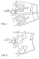
- Such a cutter is pictured schematically in Figure 2.
- the knives are such that they cut by a slicing action, with a narrow leading cutting edge slicing through the polymer.
- cutters of this type have been popular for many years, they have certain drawbacks. Among these is cutter knife breakage and/or wear, especially when hard and/or abrasive polymers are being cut.
- This invention provides an apparatus which is a rotary cutter head having an axis of rotation, comprising one or more knifes, each knife having a cutting face and a forward surface intersecting to form a cutting edge on a circumferential periphery of said rotary cutter head, characterised in that the angle between the cutting face and the forward surface forms a cutting edge angle of 70° or more, each knife having a knife angle of -10° to -15° and provided that no point on the cutting face of said knife is further from said axis of rotation of said rotary cutter head than said cutting edge.
- a rotary cutter for cutting polymer comprising, a bed knife, a rotary cutter head as defined above and a means for advancing polymers into said rotary cutter head.
- This invention also concerns a process for cutting polymer with a rotary cutter, wherein the improvement comprises, using a rotary cutter head as defined above.
- a polymer herein is meant a polymer itself containing no additives, as well as polymers containing any additive or any combination of additives normally found in polymers.
- additives include pigments such as TiO 2 , antioxidants, antiozonants, toughening agents, flame retardants, lubricants, dyes, antistatic agents, antistaining agents, and fillers and reinforcing agents such as talc, clay, carbon black, milled glass, glass fiber, carbon fiber, and aramid fiber.
- Preferred polymers are plastics (as opposed to elastomers), and thermoplastics are especially preferred.
- Figure 1 is a general view of a cross section of part of a rotary cutter head, and other parts of a cutting apparatus, according to this invention.
- the parts of the rotary cutter head shown are 1 the rotary cutter head body which rotates in the direction shown, several knives 2 , and two wedges 6 which hold the knives in place on 1 (as with bolts, whose holes are shown, but the bolts are not shown).
- Also shown is a stationary bed knife 3 whose mounting is not shown, a polymer strand 4 which is being fed in the direction shown, and a polymer granule 5 which has just been cut.
- Figure 2 shows a similar view of a conventional polymer cutter which has rotary cutter body 7 , several knives 8 , and wedges 9 to hold the knives in place. Also shown are a bed knife 10 , polymer strand 11 , and cut polymer granule 12 .
- the major difference between the instant invention and the conventional cutter is that the conventional cutter acts in a cutting mode, much as a razor blade does in cutting a beard, while the cutter of this invention acts more by shearing off the polymer.
- clearance between the cutting edge of each knife and the bed knife be as small as practicable. This tends to give the cleanest cut, and is usually about 0.025 to about 0.25 mm, preferably about 0.050 to about 0.12 mm.
- the polymer is advancing into the rotor knives continuously, so after the cutting edge of each knife passes the bed knife, each cutter knife is raked away from the edge of the bed knife.
- the point on the knife furthest away from the axis of rotation of the rotary cutter head is normally the cutting edge of the knife, and all points on the cutting edge face are closer to the axis of rotation of the rotary cutter head than the cutting edge.
- the rotary cutter head or its parts other than the knives are also preferably designed to allow the polymer to advance. In the case of Figure 1, the rotor body and wedges are rated away from the periphery of the cutter head as shown. Other designs will be obvious to the artisan to accomplish this.
- the knives may be separate parts which can be removed from the rotary cutter head for sharpening or replacement, or other configurations are possible, which can be held in the rotary cutter head by bolts, or as shown by wedges.
- the rotary cutter head may be a single piece of metal, with the knife edges hardened. This eliminates much machining of wedges, holes, etc., which are shown in Figure 1. This is particularly useful where the knife edges don't chip or need sharpening very often.
- Figure 3 shows a cross section perpendicular to the axis of rotation of a full rotary cutter head according to this invention.
- This head has a center of rotation 24 , a body 25 , a multiplicity of knives 26 , held to the body with a multiplicity of wedges 27 . In operation the head rotates in the direction shown.
- FIG. 4 is a schematic diagram showing important elements of the rotary cutter head of this invention and their relationship to each other. Also included for completeness is abed knife.
- the rotary head cutter of Figure 4 has an axis of rotation 13 .
- a dashed line 14 (which is in fact a radius) has been drawn from 13 to the point at which a knife, 18 protrudes from 17 , the cutter body.
- a bed knife 16 having cutting edge 15 .
- knife 18 Protruding from the body 17 of the rotary cutter head is knife 18 (of course more than one knife may be present), which has knife cutting face 19 , and cutting edge 20 .
- the knife also has cutting edge angle 21 , a knife forward surface 23 , and knife angle 22 , 22 is measured from a radius such as 14 extended through the point at which 18 protrudes from 17 . Positive and negative angles of 22 are indicated on Figure 3.
- the cutting edge angle of the knife, 21 is at least 70° or more, preferably about 80° or more. This angle is the angle between the knife cutting face 19 and the knife forward surface 23 . If one or both of 19 and 23 is (are) curved, then 21 is taken as the angle between the tangent and the other arm of the angle or between the two tangents, (on one or both of 19 and 23 ) at 20 .
- the maximum value of 21 is determined by 22 and the requirement that no part of 19 be further from 13 than 20 . Since 21 is a relatively large angle, there is a considerable amount of metal (or other knife material) around, and especially in back of, 20 . It is believed that this material near the cutting edge makes 20 stronger, and thus less prone to chip. The massive amount of material about 20 also is believed to retard wear, thus reducing the frequency at which 20 must be resharpened.
- 22 is the angle between a radius from 13 , and 23 (or a tangent to 23 at 20 if 23 is a curved surface), and is about +10° to about -15°, preferably about 0° to about -5°, and especially preferably about 0°. If 22 is too positive, the shearing action of 20 against 15 may be unpaired, therefore leading to poorly cut polymer, and if 22 is too negative, it may not be possible to make 21 large enough.
- No point on 19 should be further away from 13 than 20 . This follows simply from the fact that one normally prefers to have 20 as close to 15 as is practicably while polymer is being cut. If any part of 19 is further from 13 than 20 , one simply will not be able to place 20 as close to 15 as is preferred, without having 19 strike 15 when 17 is rotating. Of course as 20 suffers some wear from cutting polymer, a small portion of 19 immediately adjacent to 20 may be further from 13 than the actual edge of 20 . This is permissible, but of course when 20 becomes badly worn it will preferably be sharpened to maintain a good polymer cut quality.
- 20 may be parallel to 13 , or may be helically disposed to 13 , with essentially the entire length of 20 being at a constant distance from 13 .
- a preferred helical angle is about 0° to about 3° from 13 .
- This invention also includes an apparatus for cutting polymers which includes the rotary cutter head described above, a bed knife, and a means for advancing polymer into the rotary tatter head.
- the bed knife is a usually stationary item that is placed so that clearance between the knives of the rotary cutter head 18 pass as close to the bed knife as reasonably possible while the rotary cutter head is rotating.
- the "knife edge" of the bed knife will usually have an angle of about 90°, and serves to keep the polymer from bending or otherwise moving as the knives 18 strike the polymer.
- the polymer is fed over a surface of the bed knife into the rotary cutter head, as shown in Figures 1 and 2.
- the polymer 4 or 11 is usually advanced continuously as shown in Figures 1 and 2, respectively, into the path of the knives 2 or 8 of the rotary cutter head. This requires a means for advancing the polymer. If the cotter apparatus is so disposed the polymer may "fall" into the rotary cutter head by gravity. More commonly though the polymer is fed by means of one or more pairs of feed rolls or a pair of feed conveyors. By feed rolls is meant a pair of rolls having a nip between them. Polymer is fed into the nip and the rolls are driven to move the polymer through the nip and into the rotary cutter head.
- a feed conveyor is similar, being a conveyor-like apparatus with two conveyor belts with the polymer being driven between the belts. The polymer may simply be fed by being extruded from a die, the movement though and out of the die being the feed mechanism to the rotary cutter head. Other methods of feeding are known.
- One preferred four to be cut is one or more polymer strands.
- a strand is meant a rod-like essentially continuous length of polymer whose largest cross sectional dimension is no more than 6 times, preferably no more than 3 times, and more preferably no more than 2 times greater than its smallest cross sectional dimension.
- a preferred cross sectional for a strand is approximately circular or square, with circular being especially preferred. It is preferred that the largest cross sectional dimension of the strand be about 1 to about 8 mm, preferably about 2 mm to about 4 mm.
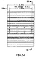
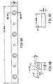
- a Model 3508 cutter made by Conair Corp., Bay City, MI, U.S.A. was used to cut circular cross section polymer strands.
- the cutter head was used is shown in Figures 5 and 6.
- the diameter of the strands entering the cutter was about 2.3 mm, and the length of the pellet produced was about 2.5 mm.
- the strands were extruded through die holes about 4.0 to 4.5 mm in diameter and the strands (while molten) were drawn down to about 2.3 mm diameter by the feed mechanism of the cutter.
- the clearance between the rotor knives and the bed knife was nominally 0.076 mm.
- the individual polymers cut at different times were poly(ethylene terephthalate), poly(butylene terephthalate), nylon-6,6 and apolyamide containing both aromatic and aliphatic repeat units. All of these polymers gave a good cut throughout the test, with for instance the amount of fines being produced at the beginning and end of the test on various polymers not differing much. The results were also comparable to those which were usually obtained with the same cutter using a conventional type rotary cutter head, as shown in Figure 2.
Landscapes
- Engineering & Computer Science (AREA)
- Mechanical Engineering (AREA)
- Life Sciences & Earth Sciences (AREA)
- Forests & Forestry (AREA)
- Processing And Handling Of Plastics And Other Materials For Molding In General (AREA)
Abstract
Claims (15)
- Appareil consistant en une tête de coupe rotative (1) pourvue d'un axe de rotation (13), comprenant un ou plusieurs couteau(x) (2, 18), chaque couteau possédant une face coupante (19) et une surface avant (23) qui se coupent pour former une arête de coupe (20) sur une périphérie circonférentielle de ladite tête de coupe rotative (1), dans lequel
chaque couteau présente un angle de couteau (22) compris entre +10° et -15°, et à condition qu'aucun point de la face coupante (19) dudit couteau (2, 18) ne soit plus éloigné dudit axe de rotation (13) de ladite tête de coupe rotative (1) que ladite arête de coupe; caractérisé par le fait que
l'angle entre la face coupante (19) et la surface avant (23) est un angle d'arête de coupe (21) supérieur ou égal à 70°. - Appareil pour couper un polymère (4), comprenant, en outre, un couteau fixe (3, 16), appareil consistant en une tête de coupe rotative (1) selon la revendication 1 et moyen pour faire avancer le polymère dans ladite tête de coupe rotative.
- Appareil selon la revendication 1 ou 2, dans lequel ledit angle d'arête de coupe (21) est supérieur ou égal à 80°.
- Appareil selon la revendication 1 ou 2, dans lequel ledit angle de couteau (22) est compris entre 0° et -5°.
- Appareil selon la revendication 2, dans lequel une distance entre ladite arête de coupe (20) et ledit couteau fixe (3 , 16) est comprise entre 0,025 mm et 0,25 mm.
- Appareil ou procédé selon l'une quelconque des revendications précédentes, dans lequel un angle hélicoïdal entre ledit axe de rotation (13) et ladite arête de coupe (20) est compris entre 0° et 3°.
- Procédé pour couper un polymère (4) avec une coupeuse rotative, dans lequel l'amélioration comprend l'utilisation d'une tête de coupe rotative (1) selon la revendication 1 ou l'une quelconque des revendications 3 à 6 lorsqu'elles dépendent de celle-ci.
- Procédé selon la revendication 7, dans lequel une distance entre ladite arête de coupe (20) et un couteau fixe (3 , 16) est comprise entre 0,025 mm et 0,25 mm.
- Procédé selon la revendication 7 ou 8, dans lequel ledit polymère est un thermoplastique.
- Procédé selon la revendication 9, dans lequel ledit polymère se présente à l'origine sous la forme d'un fil de base.
- Procédé selon la revendication 9 ou 10, dans lequel ledit polymère (4) est alimenté de manière continue vers ladite tête de coupe rotative (1).
- Procédé selon la revendication 10, dans lequel une dimension minimale de la section transversale dudit fil de base est 2 mm.
- Procédé selon la revendication 10 ou 12, dans lequel ledit fil de base a une section transversale circulaire ou carrée.
- Procédé selon l'une quelconque des revendications 8 à 13, dans lequel ledit polymère (4) contient au moins une matière de remplissage ou un agent de renforcement.
- Procédé selon l'une quelconque des revendications 8 à 14, dans lequel on produit des pastilles ou des granules (12) dudit polymère.
Applications Claiming Priority (1)
| Application Number | Priority Date | Filing Date | Title |
|---|---|---|---|
| PCT/US1997/017630 WO1999016599A1 (fr) | 1997-09-29 | 1997-09-29 | Appareil et procede de coupe de polymere |
Publications (2)
| Publication Number | Publication Date |
|---|---|
| EP1019227A1 EP1019227A1 (fr) | 2000-07-19 |
| EP1019227B1 true EP1019227B1 (fr) | 2003-06-04 |
Family
ID=22261784
Family Applications (1)
| Application Number | Title | Priority Date | Filing Date |
|---|---|---|---|
| EP97909910A Expired - Lifetime EP1019227B1 (fr) | 1997-09-29 | 1997-09-29 | Appareil et procede de coupe de polymere |
Country Status (7)
| Country | Link |
|---|---|
| EP (1) | EP1019227B1 (fr) |
| JP (1) | JP4249386B2 (fr) |
| KR (1) | KR100556176B1 (fr) |
| AU (1) | AU4741297A (fr) |
| CA (1) | CA2299551C (fr) |
| DE (1) | DE69722675T2 (fr) |
| WO (1) | WO1999016599A1 (fr) |
Families Citing this family (1)
| Publication number | Priority date | Publication date | Assignee | Title |
|---|---|---|---|---|
| US20020069732A1 (en) * | 1999-12-10 | 2002-06-13 | Waggoner Marion G. | Polymer cutting apparatus and method |
Family Cites Families (9)
| Publication number | Priority date | Publication date | Assignee | Title |
|---|---|---|---|---|
| US3583267A (en) * | 1966-10-31 | 1971-06-08 | Dow Chemical Co | Method and apparatus for pelletizing of plastic materials |
| DE2538174B2 (de) * | 1975-08-27 | 1979-01-04 | Bayer Ag, 5090 Leverkusen | Zerkleinerungsvorrichtung für Kunststoffstränge |
| US4090674A (en) * | 1977-01-21 | 1978-05-23 | Dow Badische Canada Limited | Fixed cutting element |
| JPS59190511U (ja) * | 1983-01-24 | 1984-12-18 | 中村 謙作 | 樹脂ペレツトの製造装置 |
| EP0377060B1 (fr) * | 1989-01-03 | 1993-08-18 | Hans Hench | Outil de coupe rotatif, en particulier pour la granulation de rubans de matière synthétique |
| GB2257084B (en) * | 1991-06-27 | 1994-08-31 | Hitachi Metals Ltd | Rotary-type sheet cutter |
| JP2655965B2 (ja) * | 1991-12-26 | 1997-09-24 | 積水化成品工業株式会社 | 樹脂のホットカット装置 |
| KR960008493Y1 (ko) * | 1993-12-02 | 1996-10-02 | 주식회사 동양테크 | 로타리 커터 |
| JP3701710B2 (ja) * | 1995-05-26 | 2005-10-05 | 日本クラウンコルク株式会社 | 合成樹脂素材供給装置 |
-
1997
- 1997-09-29 JP JP2000513715A patent/JP4249386B2/ja not_active Expired - Fee Related
- 1997-09-29 EP EP97909910A patent/EP1019227B1/fr not_active Expired - Lifetime
- 1997-09-29 KR KR1020007003291A patent/KR100556176B1/ko not_active Expired - Fee Related
- 1997-09-29 AU AU47412/97A patent/AU4741297A/en not_active Abandoned
- 1997-09-29 DE DE69722675T patent/DE69722675T2/de not_active Expired - Lifetime
- 1997-09-29 CA CA002299551A patent/CA2299551C/fr not_active Expired - Fee Related
- 1997-09-29 WO PCT/US1997/017630 patent/WO1999016599A1/fr not_active Ceased
Also Published As
| Publication number | Publication date |
|---|---|
| JP2001518400A (ja) | 2001-10-16 |
| AU4741297A (en) | 1999-04-23 |
| CA2299551C (fr) | 2006-11-14 |
| DE69722675T2 (de) | 2004-04-29 |
| DE69722675D1 (de) | 2003-07-10 |
| CA2299551A1 (fr) | 1999-04-08 |
| KR100556176B1 (ko) | 2006-03-03 |
| EP1019227A1 (fr) | 2000-07-19 |
| JP4249386B2 (ja) | 2009-04-02 |
| WO1999016599A1 (fr) | 1999-04-08 |
| KR20010015637A (ko) | 2001-02-26 |
Similar Documents
| Publication | Publication Date | Title |
|---|---|---|
| EP1984157B1 (fr) | Moyeu de trancheuse dote de lames a bords emousses fortement inclinees | |
| US6247389B1 (en) | Polymer cutting apparatus and method | |
| CA1176811A (fr) | Traitement de materiaux en elastomere | |
| EP3638468B1 (fr) | Machine de réduction de taille et unité de réduction de taille associée | |
| CN103889674B (zh) | 用于制备塑料材料的装置 | |
| CN102046294B (zh) | 用片材生产颗粒的切碎机 | |
| CN103958141B (zh) | 用于制备塑料材料的装置 | |
| JP6219829B2 (ja) | プラスチック材料処理装置 | |
| JP6174589B2 (ja) | プラスチック材料処理装置 | |
| EP1235670B1 (fr) | Appareil et procede de coupe de polymere | |
| US3353754A (en) | Process and apparatus for cutting synthetic polymer sheets into chips | |
| JPH07302B2 (ja) | ストランドカッター | |
| CA2299551C (fr) | Appareil et procede de coupe de polymere | |
| US20040025658A1 (en) | Polymer cutting apparatus and method | |
| CN1113733C (zh) | 聚合物的切割装置和切割方法 | |
| CN108525804A (zh) | 切刀装置及物料切割机构 | |
| US3831480A (en) | Rotary cutter-slitter for high speed bursting apparatus | |
| CN214353556U (zh) | 一种塑胶加工用均匀切粒装置 | |
| CN115570701B (zh) | 一种mbs树脂生产用造粒机的水下切粒单元 | |
| CN110948733A (zh) | 薄膜回收造粒装置 | |
| EP0596673B1 (fr) | Cisaille à lame rotative | |
| JPH072331B2 (ja) | ストランドカッター | |
| GB2387341A (en) | Shredding machine with radially-tipped cutting teeth | |
| HK1214567A1 (zh) | 用於对塑料材料进行预处理的装置 | |
| HK1214567B (en) | Apparatus for processing plastic material |
Legal Events
| Date | Code | Title | Description |
|---|---|---|---|
| PUAI | Public reference made under article 153(3) epc to a published international application that has entered the european phase |
Free format text: ORIGINAL CODE: 0009012 |
|
| 17P | Request for examination filed |
Effective date: 20000224 |
|
| AK | Designated contracting states |
Kind code of ref document: A1 Designated state(s): BE DE FR GB IT NL |
|
| 17Q | First examination report despatched |
Effective date: 20010226 |
|
| GRAH | Despatch of communication of intention to grant a patent |
Free format text: ORIGINAL CODE: EPIDOS IGRA |
|
| GRAH | Despatch of communication of intention to grant a patent |
Free format text: ORIGINAL CODE: EPIDOS IGRA |
|
| GRAA | (expected) grant |
Free format text: ORIGINAL CODE: 0009210 |
|
| AK | Designated contracting states |
Designated state(s): BE DE FR GB IT NL |
|
| REG | Reference to a national code |
Ref country code: GB Ref legal event code: FG4D |
|
| REF | Corresponds to: |
Ref document number: 69722675 Country of ref document: DE Date of ref document: 20030710 Kind code of ref document: P |
|
| ET | Fr: translation filed | ||
| PLBE | No opposition filed within time limit |
Free format text: ORIGINAL CODE: 0009261 |
|
| STAA | Information on the status of an ep patent application or granted ep patent |
Free format text: STATUS: NO OPPOSITION FILED WITHIN TIME LIMIT |
|
| 26N | No opposition filed |
Effective date: 20040305 |
|
| PGFP | Annual fee paid to national office [announced via postgrant information from national office to epo] |
Ref country code: GB Payment date: 20120926 Year of fee payment: 16 |
|
| PGFP | Annual fee paid to national office [announced via postgrant information from national office to epo] |
Ref country code: IT Payment date: 20120921 Year of fee payment: 16 Ref country code: FR Payment date: 20120926 Year of fee payment: 16 |
|
| PGFP | Annual fee paid to national office [announced via postgrant information from national office to epo] |
Ref country code: NL Payment date: 20120908 Year of fee payment: 16 Ref country code: BE Payment date: 20120912 Year of fee payment: 16 |
|
| PGFP | Annual fee paid to national office [announced via postgrant information from national office to epo] |
Ref country code: DE Payment date: 20130925 Year of fee payment: 17 |
|
| BERE | Be: lapsed |
Owner name: E.I. *DU PONT DE NEMOURS AND CY Effective date: 20130930 |
|
| REG | Reference to a national code |
Ref country code: NL Ref legal event code: V1 Effective date: 20140401 |
|
| GBPC | Gb: european patent ceased through non-payment of renewal fee |
Effective date: 20130929 |
|
| REG | Reference to a national code |
Ref country code: FR Ref legal event code: ST Effective date: 20140530 |
|
| PG25 | Lapsed in a contracting state [announced via postgrant information from national office to epo] |
Ref country code: GB Free format text: LAPSE BECAUSE OF NON-PAYMENT OF DUE FEES Effective date: 20130929 Ref country code: BE Free format text: LAPSE BECAUSE OF NON-PAYMENT OF DUE FEES Effective date: 20130930 |
|
| PG25 | Lapsed in a contracting state [announced via postgrant information from national office to epo] |
Ref country code: IT Free format text: LAPSE BECAUSE OF NON-PAYMENT OF DUE FEES Effective date: 20130929 Ref country code: NL Free format text: LAPSE BECAUSE OF NON-PAYMENT OF DUE FEES Effective date: 20140401 Ref country code: FR Free format text: LAPSE BECAUSE OF NON-PAYMENT OF DUE FEES Effective date: 20130930 |
|
| REG | Reference to a national code |
Ref country code: DE Ref legal event code: R119 Ref document number: 69722675 Country of ref document: DE |
|
| PG25 | Lapsed in a contracting state [announced via postgrant information from national office to epo] |
Ref country code: DE Free format text: LAPSE BECAUSE OF NON-PAYMENT OF DUE FEES Effective date: 20150401 |