EP1020320B1 - Einrichtung und Verfahren für die Detektion von sitzenden Insassen - Google Patents
Einrichtung und Verfahren für die Detektion von sitzenden Insassen Download PDFInfo
- Publication number
- EP1020320B1 EP1020320B1 EP00100659A EP00100659A EP1020320B1 EP 1020320 B1 EP1020320 B1 EP 1020320B1 EP 00100659 A EP00100659 A EP 00100659A EP 00100659 A EP00100659 A EP 00100659A EP 1020320 B1 EP1020320 B1 EP 1020320B1
- Authority
- EP
- European Patent Office
- Prior art keywords
- seat
- sensor
- seat cushion
- passenger
- rail
- Prior art date
- Legal status (The legal status is an assumption and is not a legal conclusion. Google has not performed a legal analysis and makes no representation as to the accuracy of the status listed.)
- Expired - Lifetime
Links
Images





Classifications
-
- B—PERFORMING OPERATIONS; TRANSPORTING
- B60—VEHICLES IN GENERAL
- B60N—SEATS SPECIALLY ADAPTED FOR VEHICLES; VEHICLE PASSENGER ACCOMMODATION NOT OTHERWISE PROVIDED FOR
- B60N2/00—Seats specially adapted for vehicles; Arrangement or mounting of seats in vehicles
- B60N2/02—Seats specially adapted for vehicles; Arrangement or mounting of seats in vehicles the seat or part thereof being movable, e.g. adjustable
- B60N2/04—Seats specially adapted for vehicles; Arrangement or mounting of seats in vehicles the seat or part thereof being movable, e.g. adjustable the whole seat being movable
- B60N2/06—Seats specially adapted for vehicles; Arrangement or mounting of seats in vehicles the seat or part thereof being movable, e.g. adjustable the whole seat being movable slidable
- B60N2/07—Slide construction
- B60N2/0722—Constructive details
- B60N2/0732—Attachment of seat frame to the slide, e.g. eyelets
-
- B—PERFORMING OPERATIONS; TRANSPORTING
- B60—VEHICLES IN GENERAL
- B60N—SEATS SPECIALLY ADAPTED FOR VEHICLES; VEHICLE PASSENGER ACCOMMODATION NOT OTHERWISE PROVIDED FOR
- B60N2/00—Seats specially adapted for vehicles; Arrangement or mounting of seats in vehicles
- B60N2/002—Seats provided with an occupancy detection means mounted therein or thereon
- B60N2/0021—Seats provided with an occupancy detection means mounted therein or thereon characterised by the type of sensor or measurement
- B60N2/0024—Seats provided with an occupancy detection means mounted therein or thereon characterised by the type of sensor or measurement for identifying, categorising or investigation of the occupant or object on the seat
- B60N2/0025—Seats provided with an occupancy detection means mounted therein or thereon characterised by the type of sensor or measurement for identifying, categorising or investigation of the occupant or object on the seat by using weight measurement
-
- B—PERFORMING OPERATIONS; TRANSPORTING
- B60—VEHICLES IN GENERAL
- B60N—SEATS SPECIALLY ADAPTED FOR VEHICLES; VEHICLE PASSENGER ACCOMMODATION NOT OTHERWISE PROVIDED FOR
- B60N2/00—Seats specially adapted for vehicles; Arrangement or mounting of seats in vehicles
- B60N2/002—Seats provided with an occupancy detection means mounted therein or thereon
- B60N2/0021—Seats provided with an occupancy detection means mounted therein or thereon characterised by the type of sensor or measurement
- B60N2/003—Seats provided with an occupancy detection means mounted therein or thereon characterised by the type of sensor or measurement characterised by the sensor mounting location in or on the seat
-
- B—PERFORMING OPERATIONS; TRANSPORTING
- B60—VEHICLES IN GENERAL
- B60R—VEHICLES, VEHICLE FITTINGS, OR VEHICLE PARTS, NOT OTHERWISE PROVIDED FOR
- B60R21/00—Arrangements or fittings on vehicles for protecting or preventing injuries to occupants or pedestrians in case of accidents or other traffic risks
- B60R21/01—Electrical circuits for triggering passive safety arrangements, e.g. airbags, safety belt tighteners, in case of vehicle accidents or impending vehicle accidents
- B60R21/015—Electrical circuits for triggering passive safety arrangements, e.g. airbags, safety belt tighteners, in case of vehicle accidents or impending vehicle accidents including means for detecting the presence or position of passengers, passenger seats or child seats, and the related safety parameters therefor, e.g. speed or timing of airbag inflation in relation to occupant position or seat belt use
- B60R21/01512—Passenger detection systems
Definitions
- the present invention relates to a sitting passenger detecting apparatus according to the preamble of claim 1, and more particularly to a sitting passenger detecting apparatus which is applied to a seat disposed to be movable in the longitudinal direction on a floor of a vehicle, such as an automobile.
- JP 9-207638 A An example of a sitting passenger detecting apparatus disposed to be movable in the longitudinal direction on a floor of a vehicle, such as an automobile, has been disclosed in JP 9-207638 A .
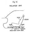
- the sitting passenger detecting apparatus incorporates load sensors 606 each of which is interposed between a seat joining portion 604 for joining a seat 600 to a floor 602 and a joining portion 602A of the floor 602.
- the number of the load sensors 606 is two which is the minimum number.
- the load sensors 606 are disposed at the two ends of a diagonal of the seat joining portions 604 which are usually provided for four portions.
- the foregoing sitting passenger detecting apparatus incorporates the load sensor 606 provided for a portion for joining the seat joining portion 604 provided for a lower rail of a seat track 610 and the floor 602 to each other. Therefore, when the seat 600 has been moved rearwards along the seat track 610 and a seat back 600A has been reclined rearwards, the load of the passenger resting against the seat back 600A sometimes causes an upward load to be applied to the front seat joining portion 604. As a result, the load sensor 606 provided for the front seat joining portion 604 cannot substantially measure the load. Hence it follows that the measuring accuracy cannot be improved.
- an initial value (initial distortion) of the load sensor 606 of the above-mentioned sitting passenger detecting apparatus is enlarged excessively.
- the variation (varied distortion) of the load sensor 606 which is caused by the load which must be measured is reduced with respect to the initial value. Since the variation with respect to the initial value is reduced as described above, the measuring accuracy cannot be improved.
- a generic sitting passenger detecting apparatus having all feature of the preamble of claim 1 is known from JP-A-9-150662 .
- a sitting passenger detecting apparatus has connecting members which are structured to separate a seat rail and a seat cushion frame from each other.
- the connecting member is a bracket which is provided for the rear connecting portion of the front and rear connecting portions between an upper rail of the seat rail and the seat cushion frame.
- a displacement detecting means detects a displacement of the seat cushion frame. Based on that value, a weight calculating means calculates the weight of the passenger sitting on the seat.
- a further sitting passenger detecting apparatus is known from JP-A-9-301120 .
- the displacement detecting means detects a strain of a ridge part for holding the seat.
- the displacement detecting means is integrated in the seat between the cushion and the seat cushion frame.
- this object is achieved by a sitting passenger detecting apparatus having the features of claim 1.
- the seat cushion frame When a passenger sits on the seat, the seat cushion frame is relatively moved with respect to the seat rail. The relative displacement is detected by the displacement detecting means. In accordance with a detected value, the weight calculating means calculates the weight of the sitting passenger. Therefore, if the seat is slid in the longitudinal direction, the relative position between the seat rail and the seat cushion frame is not changed. As a result, the load which is added to the seat can accurately be measured. Hence it follows that the accuracy of measuring the weight of the passenger sitting on the seat can be improved.
- the sitting passenger detecting apparatus incorporates the connecting member which is a bracket provided for at least the rear connecting portion of the front and rear connecting portions between the upper rail of the seat rails and the seat cushion frame.
- the displacement detecting means is a sensor for detecting change in the distance from the seat rail to the seat cushion frame. The sensor is disposed in parallel with the bracket at an offset position in a direction of the width of the seat.
- the load added to the seat cushion frame downwards compresses and deforms the bracket.
- the distance between the seat cushion frame and the bracket is shortened. Since the foregoing change is detected by the sensor, the accuracy of measuring the weight of the passenger sitting in the seat can be improved. If the upper rail and the seat cushion frame are firmly joined to each other, the foregoing state does not exert a great influence on the displacement of the sensor joining portion. As a result, the seat support rigidity can be increased without any deterioration in the measuring accuracy of the sensor. As a result, the comfort of the seat can be improved.
- the foregoing sensor may comprise a thin plate which is distorted in accordance with change in the distance from the seat cushion frame and the upper rail; and a sensor body for detecting distortion of the thin plate.
- the thin plate is distorted when the distance between the seat cushion frame and the upper rail has been changed.
- the distortion is detected by the sensor body.
- the structure can be simplified.
- the foregoing bracket may incorporate a bending portion which is elastically deformed in a downward direction owing to the load which is added to the seat when a passenger has sat in the seat.
- the load which is added to the seat after the passenger has sat in the seat elastically deforms the bending portion of the bracket.
- the distance between the seat cushion frame and the upper rail can be changed, causing the structure to be simplified.
- a deformation detection sensor disposed on a lower rail portion of the seat rail for detecting a predetermined deformation thereon and alarm means for alarming based on output signals of the deformation sensor.
- the weight of the passenger sitting on the seat may not be measured accurately when the lower rail portion of the seat rail is deformed owing to the vehicle collision or the like.
- the deformation occurred in the lower rail portion can be detected by the deformation detection sensor and the passenger is alarmed to abnormality in the sitting passenger detecting function by the alarm means.
- the passenger is alarmed to abnormality in the sitting passenger detecting function by the alarm means when a changing rate of output signals from the sensor disposed on the in parallel with the bracket disposed either at the inner side or the outer side in a lateral direction of a vehicle exceeds a predetermined change rate.
- an arrow FR indicates a forward direction of a vehicle
- an arrow UP indicates an upward direction of the vehicle
- an arrow IN indicates an inward direction of the width of the vehicle.
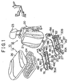
- a seat 10 for a vehicle constitutes a front passenger seat of a vehicle 12.
- a seat back 16 rotatable in the longitudinal direction is joined to the rear portion of a seat cushion 14.
- a shaft 22 is arranged between rear ends 18A of right and left seat cushion frames 18 which form one pair.
- a seat-back frame 20 to which a seat-back pad 21, a headrest 23 and so forth are installed is joined rotatively about the shaft 22 in the longitudinal direction.
- a portion in which the seat cushion frames 18 and the seat-back frame 20 are connected to each other is provided with a known reclining mechanism (not shown).
- Flanges 18B and 18C facing outwards in the widthwise direction of the seat are formed in the peripheries at two vertical ends of the seat cushion frames 18.
- Front and rear joining brackets 19 forming one pair are secured to the inner surfaces of vertical walls 18D of the seat cushion frames 18 in the direction of the width of the seat.
- a seat-cushion pan 24 is secured to the seat cushion frames 18 through the joining brackets 19. Note that a seat-cushion pad 26 is disposed on the seat-cushion pan 24.
- joining portions 30A and 30B are formed at the two longitudinal ends of a lower rail 30 of the seat rail 27.
- the joining portions 30A and 30B are, with bolts 32, secured to front and rear floor cross members 36 and 38 disposed on the floor 34 in the direction of the width of the vehicle.
- a lower portion 28A of an upper rail 28 of the seat rail 27 is engaged to the lower rail 30 slidably in the longitudinal direction.
- a flange 28B facing outside in the direction of the width of the seat is formed at the top end of the upper rail 28. Since nails and locking mechanism for fixing the position of the upper rail 28 with respect to the lower rail 30 have known structures, the structures are omitted from description and illustration.
- a sensor joining portion 40 facing downwards is formed adjacent to each of the two longitudinal ends of the flange 28B of the upper rail 28.
- Each sensor joining portion 40 has an inverted trapezoidal side cross sectional shape.
- a sensor joining portions 42 facing upwards is formed adjacent to each of the two longitudinal ends of the lower flange 18C of the seat cushion frames 18.
- Each sensor joining portions 42 has a trapezoidal side cross sectional shape.
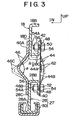
- a thin plate 44 constituting a sensor, which is a displacement detecting means, is arranged between the sensor joining portion 40 of the upper rail 28 and the sensor joining portions 42 of the seat cushion frames 18.
- each of the thin plate 44 and the bracket 46 has a rectangular cross sectional shape, the lengthwise direction of which is the vertical direction.
- the bracket 46 is downwards compressed and deformed as indicated with an alternate long and two dashed line shown in FIG. 3 owing to a vertical load added in between the upper rail 28 and the seat cushion frames 18 so that the distance between the upper rail 28 and the seat cushion frames 18 is changed.
- the bracket 46 has sufficient rigidity to prevent breakage.
- the bracket 46 After the load has been released, the bracket 46 must restore its original shape indicated with a solid line shown in FIG. 3. Therefore, spring steel must be employed and angle ⁇ of the bent portion must be enlarged.
- a flat plate bent into a wedge shape facing side as shown in FIG. 3 is employed if the relationship with near elements is not limited.
- a joining hole 48 is formed adjacent to each of two vertical ends of the thin plate 44.
- the joining holes 48 are formed into elongated holes, the lengthwise direction of each of which is the vertical direction.
- a joining hole 50 is formed in the sensor joining portions 42 of the seat cushion frames 18.
- a joining hole 52 is formed in the sensor joining portion 40 of the upper rail 28.
- Bolts 54 are, from outside in the direction of the width of the seat 10, inserted into the joining holes 48 and 50 and the joining holes 48 and 52.
- a thread portion 54A of the bolt 54 is engaged to a weld nut 56 disposed at the inner portion of each of the sensor joining portions 42 and 40 in the direction of the width of the seat 10.
- the bracket 46 has an upper end 46A welded to a vertical wall 18D of the seat cushion frames 18 and a lower end 46B welded to a vertical wall 28C of the upper rail 28.
- a bent portion 46C formed at an intermediate portion of the bracket 46 in the vertical direction of the bracket 46 has a wedge-like shape facing side when the bent portion 46C is viewed from the longitudinal direction of the seat 10.
- a sensor 62 in the form of a sheet-like shape and serving as a sensor body is disposed on the outer surface 44B of the vertical central portion 44A of the thin plate 44 in the direction of the width of the seat 10. Therefore, when the seat cushion frames 18 has been moved downwards (the direction indicated with arrow A shown in FIG. 3), the vertical central portion 44A of the thin plate 44 is deformed to warp to the outside in the direction of the width of the seat 10.
- the distortion measuring sensor 62 is able to detect resulted distortion.
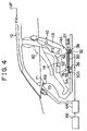
- the distortion measuring sensor 62 is connected to a control unit 64 serving as a weight calculating means.
- the control unit 64 is connected to an impact detecting sensor 66, a front passenger-seat air-bag apparatus 70 disposed in an instrument panel 68 and an indicator 71 disposed on the instrument panel 68.
- the control unit 64 controls the operation and output of the inflator of a front passenger-seat air-bag apparatus 70. Moreover, when the passenger 60 is not sitting on the seat 10, the control unit 64 turns the indicator 71 on to make a driver or the like to know a fact that the front passenger-seat air-bag apparatus 70 is not operated if a state in which the front passenger-seat air-bag apparatus 70 must be operated owing to collision or whatsoever.
- the weight of the passenger 60 who has sat on the seat 10 is, as shown in FIG. 4, mainly added to a rear portion 14A of the seat cushion 14 and the seat back 16, as indicated with arrows F1 and F2 shown in FIG. 4.
- the upper rail 28 is pressed downwards, causing the bent portion 46C of the bracket 46 to be compressed and deformed downwards, as indicated with the alternate long and two dashed line shown in FIG. 3. Therefore, the seat cushion frames 18 is moved downwards (the direction indicated with arrow A shown in FIG. 3).
- the vertical central portion 44A of the thin plate 44 is warped outwards in the direction of the width of the seat 10. Therefore, caused distortion can be detected by the sensor 62.
- the right and left upper rails 28 and the right and left seat cushion frames 18 are connected to each other through front and rear brackets 46 which form a pair.
- the foregoing connecting portions are formed at offset positions from the portion for joining the sensor 62 in the direction of the width of the seat 10 (in the longitudinal direction of the vehicle).
- any influence of the clamping force between the upper rail and the seat cushion frame is not exerted on a value measured by the sensor 62 as distinct from the conventional structure.
- the force for connecting the upper rail 28 and the seat cushion frames 18 to each other is enlarged, the detecting accuracy of the sensor 62 does not deteriorate.
- the measuring accuracy can be improved and the lateral rigidity of the portion for joining the seat cushion frames 18 to the upper rail 28 can be maintained. As a result, the comfort of the seat can be improved.
- change in the load owing to the passenger 60 sitting in the seat 10 can accurately be detected without any influence of the longitudinal slide position of the seat 10.
- the first embodiment is structured such that the joining holes 48 of the thin plate 44 is formed into the elongated hole extending in the vertical direction. Therefore, if the bracket 46 is deformed, the clamping position of the joining holes 48 can easily be shifted to a position at which the thin plate 44 is clamped in a state in which no load is added.
- the first embodiment is structured such that the bent portion 40C of the bracket 46 is formed into the wedge shape facing side when the bent portion 40C is viewed from the longitudinal direction of the seat 10.
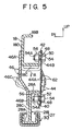
- the bent portion 46C of the bracket 46 may be bent downwards to the outside in the direction of the width of the seat 10 when the vertical wall 28C of the upper rail 28 is offset to the outside in the direction of the width of the seat 10 with respect to the vertical wall 18D of the seat cushion frames 18.
- the bent portion 46C may be compressed and deformed in a downward direction as indicated with an alternate long and two dashed line shown in FIG. 5.
- a structure as shown in FIG. 6 may be employed in which joining holes 74 and 76 are formed in the vertical wall 18D of the seat cushion frames 18 and the vertical wall 28C of the upper rail 28. Moreover, joining holes 78 and 80 are formed in the two vertical end portions 46A and 46B of the bracket 46. A bolt 54 and a nut 56 are used to join the bracket 46 to the vertical wall 18D of the seat cushion frames 18 and the vertical wall 28C of the upper rail 28. In addition, the thin plate 44 provided with the sensor 62 is clamped in between the vertical wall 18D of the seat cushion frames 18 and the vertical wall 28C of the upper rail 28.
- FIG. 7 A second embodiment of the sitting passenger detecting apparatus according to the present invention will now be described with reference to FIG. 7.
- the second embodiment has the structure that two longitudinal positions of the vertical wall 18D of the seat cushion frames 18 and the vertical wall 28C of the upper rail 28 are connected to each other by the brackets 46. Moreover, the thin plate 44 provided with the distortion measuring sensor 62 is disposed. The passenger 60 usually sits in the rear portion of the seat cushion 14. Therefore, a structure arranged as shown in FIG. 32 may be employed in which the rear portion of the seat cushion frames 18 and the rear portion of the upper rail 28 are connected to each other with the brackets 46. Moreover, the thin plate 44 provided with the distortion measuring sensor 62 is disposed.
- the connecting portion 18E formed in a lower portion of the front portion of the seat cushion frames 18 and the connecting portion 28D formed in the upper portion of the front portion of the upper rail 28 are rotatively connected to each other by a connecting member 80, such as a pin.
- a connecting member 80 such as a pin.
- the rectangular bracket 46 having the bent portion 46C serving as the connecting member is employed.
- the connecting member is not limited to the bracket 46. If connecting strength between the seat cushion frames 18 and the upper rail 28 can be maintained and if downward compression and deformation are permitted owing to the load added to the seat cushion frames 18, another structure may be employed.
- the sensor is constituted by the thin plate 44 and the distortion measuring sensor 62 is formed into the sheet shape. The sensor is not limited to the foregoing structure.
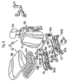
- FIGS. 8 to 11 A third embodiment of the sitting passenger detecting apparatus according to the present invention will now be described with reference to FIGS. 8 to 11.
- an inner buckle 300 is attached to a rear end portion 18A of a seat cushion frame 18 on the inner side of a seat 10 in the lateral direction.
- the inner buckle 300 is fixed to the upper portion of a bent portion 46C of a bracket 46 with a bolt 302 and a nut 304.
- a deformation detection sensor 306 used as a diagnostic sensor is disposed in the vicinity of the lower rail 30 close to the position where the inner buckle 300 is disposed, which corresponds to the position in the vicinity of the rear end portion of a flange 30D formed on the upper end portion of the side wall 30C on the inside of the lower rail 30 in the lateral direction so as to face the inside of the seat.
- the deformation detection sensor 306 serves to detect deformation of the lower rail 30.
- the deformation detection sensor 306 is connected to the control unit 64 shown in FIG. 4, which is designed to alarm an indicator 71 as the alarm means for abnormality in the sitting passenger detection function based on an output signal generated when the deformation detection sensor 306 detects the output signal (predetermined deformation) which is equal to or greater than a predetermined value.
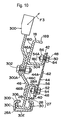
- collision of the vehicle may cause the passenger sitting on the seat 10 to apply a large load F3 upward to the inside of the vehicle body to the inner buckle 300 as shown in FIG. 10.
- a thin plate 44 provided with the deformation measurement sensor 62 also deforms, thus interfering accurate measurement of the weight of the sitting passenger.
- the control unit 64 of this embodiment is structured to execute the routine represented by a flow chart shown in FIG. 11.
- step (hereinafter referred to "S") 350 a signal output from each deformation measurement sensor 62 as a seat load sensor for detecting the weight of the passenger sitting on the seat is read, and a signal output from the deformation detection sensor 306 as the diagnostic sensor is also read.
- step S352 a determination is made whether or not an output signal from the deformation detection sensor 306 is less than a predetermined threshold value TD. If it is determined that the output signal D is less than the threshold value TD, the process proceeds to step S354.
- step S354 a seat load is operated from the output signal of each of the deformation measurement sensors 62, and a determination is made whether or not the operation result is less than a predetermined threshold value TON. If it is determined that the seat load is not less than the threshold value TON, the process proceeds to step S358 where the air bag system for a passenger seat is brought into workable state.
- step S352 the process proceeds to step S360.
- the indicator 71 as alarm means is activated (warning operated) such that the passenger is alarmed for abnormality in the sitting passenger detecting function.
- the indicator 71 when the lower rail 30 or the like of the seat rail 27 is deformed by, for example, vehicle collision, the indicator 71 is capable of alarming the passenger for the deformation.
- the deformation detection sensor 306 is disposed in the vicinity of the rear end portion of the flange 30D of the lower rail 30 formed on the upper portion of the inner wall portion 30C in the lateral direction so as to face the inside of the seat.
- the deformation detection sensor 306 does not have to be disposed in the position as described above.
- the deformation detection sensor 306 may be disposed in the vicinity of the rear end portion of the inner wall portion 30C of the lower rail 30 as shown by an alternate long and two dashed line of FIG. 9.
- the deformation detection sensor 306 may be disposed in the vicinity of the rear end of the lower wall portion 30E of the lower rail 30.
- the deformation detection sensor 306 may be disposed on the lower rail 30 at the outer side of the seat 10 in a lateral direction of a vehicle.
- the third embodiment employs the deformation detection sensor 306. However, it may be structured requiring no deformation detection sensor 306.
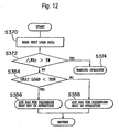
- step S370 a signal output from each of the deformation measurement sensor 62 as the seat load sensor for detecting the weight of the passenger sitting on the seat is read. Then in step S372, a determination is made whether or not a change rate ⁇ WRr of the output signal from each of the deformation measurement sensor 62 exceeds a predetermined change rate (threshold value) TW. If it is determined that the change rate ⁇ WRr exceeds the change rate TW, the process proceeds to step S374. In step S374, the indicator 71 as alarm means is activated for alarming the passenger for abnormality in the sitting passenger detection function.
- the seat is the front passenger seat.
- the seat to which the sitting passenger detecting apparatus according to the present invention is applied may be a driver's seat or another seat.
- the seat is the slide seat, the seat may be a fixed seat.
- the sitting passenger detecting apparatus according to the present invention is applied to the front passenger seat.
- the sitting passenger detecting apparatus according to the present invention may be applied to another seat except for the front passenger seat.
- a sensor attaching portion (40) of an upper rail (28) and a sensor attaching portion (42) of a cushion frame (18) are provided with a sensor attaching plate (44) having a sensor (62) disposed thereon.
- the upper rail (28) and the seat cushion frame 18 are connected with a bracket (46) at a position facing the sensor attaching plate (44).
- the seat cushion frame 18 moves down and a bent portion (46C) of the bracket (46) is pressed and deformed downwards.
- the center (44A) in the vertical direction of the sensor attaching plate (44) is bent outward in the lateral direction of the seat.
- the sensor (62) serves to detect the generated deformation.
Landscapes
- Engineering & Computer Science (AREA)
- Mechanical Engineering (AREA)
- Aviation & Aerospace Engineering (AREA)
- Transportation (AREA)
- Seats For Vehicles (AREA)
- Air Bags (AREA)
- Chair Legs, Seat Parts, And Backrests (AREA)
- Force Measurement Appropriate To Specific Purposes (AREA)
Claims (5)
- Erfassungsgerät für einen sitzenden Passagier mit:Verbindungselementen (46), die so aufgebaut sind, dass sie eine Sitzschiene (27) und einen Sitzpolsterrahmen (18) voneinander trennen, wobei das Verbindungselement (46) eine Klammer ist, die für zumindest den hinteren Verbindungsabschnitt des vorderen und des hinteren Verbindungsabschnitts zwischen einer oberen Schiene (28) der Sitzschienen (27) und dem Sitzpolsterrahmen (18) vorgesehen ist;einer Verschiebungs-Erfassungseinrichtung (44, 62) für das Erfassen einer Verschiebung des Sitzpolsterrahmens (18); undeiner Gewichts-Berechnungseinrichtung (64) für das Berechnen des Gewichts eines Passagiers, der auf dem Sitz sitzt, gemäß einem durch die Verschiebungs-Erfassungseinrichtung (44, 62) erfassten Werts,dadurch gekennzeichnet, dass
die Verbindungselemente (46) so aufgebaut sind, dass sie eine Last verwenden, die zu dem Sitzpolsterrahmen (18) so hinzuaddiert wird, dass die Sitzschiene (27) und der Sitzpolsterrahmen (18) miteinander verbunden werden, so dass eine relative Verschiebung zwischen der Sitzschiene (27) und dem Sitzpolsterrahmen (18) verhindert ist,
die Verschiebungs-Erfassungseinrichtung (44, 62) eine Verschiebung zwischen der Sitzschiene (27) und dem Sitzpolsterrahmen (18) erfasst und die Verschiebungs-Erfassungseinrichtung (44, 62) ein Sensor für das Erfassen einer Veränderung des Abstands von der Sitzschiene (27) zu dem Sitzpolsterrahmen (18) ist, wobei der Sensor parallel zu der Klammer (46) an einer Position vorgesehen ist, die in einer Richtung der Breite des Sitzes versetzt ist. - Erfassungsgerät für einen sitzenden Passagier gemäß Anspruch 1,
dadurch gekennzeichnet, dass
der Sensor eine dünne Platte (44), die gemäß der Veränderung des Abstands von dem Sitzpolsterrahmen (18) und der oberen Schiene (28) verbogen ist, und einen Sensorkörper (62) für das Erfassen der Verbiegung der dünnen Platte enthält. - Erfassungsgerät für einen sitzenden Passagier gemäß Anspruch 1,
dadurch gekennzeichnet, dass
die Klammer (46) einen Biegeabschnitt (46C) enthält, der in einer nach unten zeigenden Richtung wegen einer Last elastisch verformt wird, die zu dem Sitz hinzuaddiert wird, wenn sich einer Passagier auf den Sitz gesetzt hat. - Erfassungsgerät für einen sitzenden Passagier gemäß Anspruch 1,
gekennzeichnet durch
einen Verformungs-Erfassungssensor (306), der an einem unteren Schienenabschnitt (30) der Sitzschiene (27) angeordnet ist und eine Verformung in dem unteren Schienenabschnitt (30) erfasst; und
eine Alarmeinrichtung (71) für das Alarmgeben basierend auf einem Ausgabesignal, das erzeugt wird, wenn der Verformungs-Erfassungssensor (306) erfasst, dass die Verformung größer als eine vorbestimmte Verformung ist. - Erfassungsgerät für einen sitzenden Passagier gemäß Anspruch 1,
dadurch gekennzeichnet, dass
zwei der Klammern (46) mit den zugehörigen Sensoren (44, 62) jeweils an der Innenseite und der Außenseite des Sitzes in einer seitlichen Richtung eines Fahrzeugs angeordnet sind; wobei das Erfassungsgerät für einen sitzenden Passagier eine Alarmeinrichtung (71) für das Alarmgeben besitzt, wenn eine Veränderungsrate (ΔWRr) eines Ausgabesignals des Sensors (44, 62), der parallel zu der Klammer (46) angeordnet ist, die entweder an der Innenseite oder der Außenseite in einer seitlichen Richtung des Fahrzeugs angeordnet ist, eine vorbestimmte Veränderungsrate (TW) überschreitet.
Priority Applications (2)
| Application Number | Priority Date | Filing Date | Title |
|---|---|---|---|
| EP07110384A EP1839930B1 (de) | 1999-01-14 | 2000-01-13 | Vorrichtung und Verfahren zur Erkennung eines sitzenden Passagiers |
| EP07110386A EP1837228B1 (de) | 1999-01-14 | 2000-01-13 | Vorrichtung und Verfahren zur Erkennung eines sitzenden Passagiers |
Applications Claiming Priority (14)
| Application Number | Priority Date | Filing Date | Title |
|---|---|---|---|
| JP838099 | 1999-01-14 | ||
| JP11008380A JP2000203324A (ja) | 1999-01-14 | 1999-01-14 | 着座乗員検知装置 |
| JP4125599 | 1999-02-19 | ||
| JP4125599 | 1999-02-19 | ||
| JP11655199A JP4088736B2 (ja) | 1999-04-23 | 1999-04-23 | 車輌の乗員体重検出装置 |
| JP11655199 | 1999-04-23 | ||
| JP14224799 | 1999-05-21 | ||
| JP14224799 | 1999-05-21 | ||
| JP25077099 | 1999-09-03 | ||
| JP25077099A JP3480382B2 (ja) | 1999-09-03 | 1999-09-03 | 着座乗員検知装置及び着座乗員検知方法 |
| JP26690199 | 1999-09-21 | ||
| JP26690199 | 1999-09-21 | ||
| JP2000003293A JP3633414B2 (ja) | 1999-02-19 | 2000-01-12 | 着座乗員検知装置 |
| JP2000003293 | 2000-01-12 |
Related Child Applications (2)
| Application Number | Title | Priority Date | Filing Date |
|---|---|---|---|
| EP07110386A Division EP1837228B1 (de) | 1999-01-14 | 2000-01-13 | Vorrichtung und Verfahren zur Erkennung eines sitzenden Passagiers |
| EP07110384A Division EP1839930B1 (de) | 1999-01-14 | 2000-01-13 | Vorrichtung und Verfahren zur Erkennung eines sitzenden Passagiers |
Publications (3)
| Publication Number | Publication Date |
|---|---|
| EP1020320A2 EP1020320A2 (de) | 2000-07-19 |
| EP1020320A3 EP1020320A3 (de) | 2002-06-12 |
| EP1020320B1 true EP1020320B1 (de) | 2007-08-01 |
Family
ID=27563450
Family Applications (3)
| Application Number | Title | Priority Date | Filing Date |
|---|---|---|---|
| EP07110384A Expired - Lifetime EP1839930B1 (de) | 1999-01-14 | 2000-01-13 | Vorrichtung und Verfahren zur Erkennung eines sitzenden Passagiers |
| EP07110386A Expired - Lifetime EP1837228B1 (de) | 1999-01-14 | 2000-01-13 | Vorrichtung und Verfahren zur Erkennung eines sitzenden Passagiers |
| EP00100659A Expired - Lifetime EP1020320B1 (de) | 1999-01-14 | 2000-01-13 | Einrichtung und Verfahren für die Detektion von sitzenden Insassen |
Family Applications Before (2)
| Application Number | Title | Priority Date | Filing Date |
|---|---|---|---|
| EP07110384A Expired - Lifetime EP1839930B1 (de) | 1999-01-14 | 2000-01-13 | Vorrichtung und Verfahren zur Erkennung eines sitzenden Passagiers |
| EP07110386A Expired - Lifetime EP1837228B1 (de) | 1999-01-14 | 2000-01-13 | Vorrichtung und Verfahren zur Erkennung eines sitzenden Passagiers |
Country Status (3)
| Country | Link |
|---|---|
| US (1) | US6356200B1 (de) |
| EP (3) | EP1839930B1 (de) |
| DE (3) | DE60044988D1 (de) |
Families Citing this family (71)
| Publication number | Priority date | Publication date | Assignee | Title |
|---|---|---|---|---|
| US6689962B2 (en) * | 1995-06-07 | 2004-02-10 | Automotive Technologies International, Inc | Weight measuring system and method used with a spring system of a seat |
| US6653577B2 (en) | 1995-06-07 | 2003-11-25 | Automotive Technologies | Apparatus and method for measuring weight of an occupying item of a seat |
| US7387183B2 (en) * | 1995-06-07 | 2008-06-17 | Automotive Technologies International, Inc. | Weight measuring systems and methods for vehicles |
| US20070135982A1 (en) | 1995-06-07 | 2007-06-14 | Automotive Technologies International, Inc. | Methods for Sensing Weight of an Occupying Item in a Vehicular Seat |
| DE10005445C2 (de) * | 1999-02-08 | 2002-08-14 | Takata Corp | Diagnoseverfahren für eine Sitzlastmessvorrichtung |
| US6988413B1 (en) * | 1999-02-24 | 2006-01-24 | Siemens Vdo Automotive Corporation | Method and apparatus for sensing seat occupant weight |
| US6557424B1 (en) * | 1999-02-24 | 2003-05-06 | Siemens Vdo Automotive Corporation | Method and apparatus for sensing seat occupant weight |
| JP2001041813A (ja) * | 1999-07-27 | 2001-02-16 | Takata Corp | シート重量計測装置 |
| JP4210402B2 (ja) * | 1999-11-30 | 2009-01-21 | アイシン精機株式会社 | 車両用シート |
| DE60110549T2 (de) | 2000-01-24 | 2006-01-19 | Siemens Vdo Automotive Corporation, Auburn Hills | Kraftsensor für einen gurt |
| JP4460133B2 (ja) * | 2000-09-25 | 2010-05-12 | アイシン精機株式会社 | 車両用シート体重検出装置 |
| JP2002168682A (ja) * | 2000-11-30 | 2002-06-14 | Tachi S Co Ltd | 車両用スライドシートの荷重検出構造 |
| JP2002174556A (ja) * | 2000-12-08 | 2002-06-21 | Mitsubishi Electric Corp | 乗員検知装置 |
| US20030070846A1 (en) * | 2001-03-26 | 2003-04-17 | Trw Inc. | Parallelogram load sensing apparatus for a seat belt webbing |
| JP2002333366A (ja) * | 2001-05-08 | 2002-11-22 | Aisin Seiki Co Ltd | 乗員判定装置 |
| US6578432B2 (en) * | 2001-06-19 | 2003-06-17 | Cts Corporation | Seat belt tension sensor |
| US6776056B2 (en) * | 2001-08-06 | 2004-08-17 | Cts Corporation | Seat belt tension sensor |
| US20030066362A1 (en) * | 2001-08-29 | 2003-04-10 | Lee Shih Yuan | Seat belt tension sensor |
| JP4669175B2 (ja) * | 2001-09-13 | 2011-04-13 | アイシン精機株式会社 | 車両用シートに対するシート荷重センサの取付構造 |
| US6559392B1 (en) * | 2001-10-12 | 2003-05-06 | Lear Corporation | Weight-sensing support assembly for automotive seat cushion frame |
| US6829952B2 (en) * | 2002-02-13 | 2004-12-14 | Automotive Systems Laboratory, Inc. | Seat belt tension sensor |
| JP4136422B2 (ja) * | 2002-03-29 | 2008-08-20 | トヨタ自動車株式会社 | 着座乗員体重検知装置 |
| AU2003237468A1 (en) * | 2002-06-07 | 2003-12-22 | Automotive Systems Laboratory, Inc. | Seat belt tension sensor |
| JP4009154B2 (ja) * | 2002-07-17 | 2007-11-14 | アイシン精機株式会社 | 乗員判定装置 |
| JP3945763B2 (ja) * | 2002-08-30 | 2007-07-18 | 本田技研工業株式会社 | シートベルト装置の取付構造 |
| JP3922637B2 (ja) * | 2002-08-30 | 2007-05-30 | 本田技研工業株式会社 | サイドエアバッグシステム |
| US20060149451A1 (en) * | 2002-12-19 | 2006-07-06 | Continental Teves Ag & Co. Ohg | Method and device for detecting longitudinal and transversal acceleration of a vehicle |
| JP4250414B2 (ja) | 2002-12-24 | 2009-04-08 | アイシン精機株式会社 | レール位置検出装置 |
| JP3784376B2 (ja) * | 2003-03-19 | 2006-06-07 | 株式会社デンソー | 車両用乗員判定装置 |
| US20040232751A1 (en) * | 2003-04-30 | 2004-11-25 | Basir Otman A. | Adjustable seat with integrated occupant weight sensors |
| US6903286B2 (en) * | 2003-06-25 | 2005-06-07 | Cts Corporation | Tension sensing device |
| US7043997B2 (en) * | 2003-07-09 | 2006-05-16 | Cherry Corporation | Seat for sensing a load |
| US7299705B2 (en) * | 2003-07-15 | 2007-11-27 | Cidra Corporation | Apparatus and method for augmenting a Coriolis meter |
| JP4179546B2 (ja) * | 2003-08-26 | 2008-11-12 | タカタ株式会社 | シート重量計測装置 |
| US6859753B1 (en) | 2003-08-26 | 2005-02-22 | Robert Bosch Corporation | Apparatus and method for measuring the weight of an occupant in a vehicle |
| DE102004042840A1 (de) * | 2003-11-11 | 2005-06-09 | C. Rob. Hammerstein Gmbh & Co. Kg | Kraftfahrzeugsitz mit Erfassung des Passagiergewichts |
| JP2005219689A (ja) * | 2004-02-09 | 2005-08-18 | Denso Corp | 乗員保護装置の制御システム |
| DE102004015262B3 (de) * | 2004-03-29 | 2005-09-08 | Siemens Ag | Verfahren und Vorrichtung zum Ermitteln einer Größe, die charakteristisch ist für eine Masse, die auf einer Sitzfläche eines Sitzes ruht |
| US7333023B2 (en) * | 2004-06-10 | 2008-02-19 | Tk Holdings Inc. | Occupant classification system and method |
| US20060108167A1 (en) * | 2004-06-28 | 2006-05-25 | Brian Finger | Apparatus and method to encourage seat belt use |
| US7210358B2 (en) * | 2004-07-15 | 2007-05-01 | Honda Motor Co., Ltd. | Force sensor assembly |
| JP4695358B2 (ja) | 2004-07-30 | 2011-06-08 | テイ・エス テック株式会社 | 車両用シートの乗員重量測定装置 |
| WO2006011598A1 (ja) | 2004-07-30 | 2006-02-02 | Ts Tech Co., Ltd. | 車両用シート及び車両用シートの乗員重量測定装置 |
| JP4050729B2 (ja) | 2004-07-30 | 2008-02-20 | テイ・エス テック株式会社 | 車両用シートの乗員重量測定装置 |
| JP4677771B2 (ja) * | 2004-11-22 | 2011-04-27 | アイシン精機株式会社 | シート上荷重検出装置 |
| US7455343B2 (en) * | 2005-09-12 | 2008-11-25 | Ts Tech Co., Ltd. | Passenger's weight measurement device for vehicle seat and attachment structure for load sensor |
| CN101277845B (zh) * | 2005-09-30 | 2010-09-08 | 东京座椅技术股份公司 | 车辆用座椅的乘员重量测量装置 |
| JP2007099215A (ja) * | 2005-10-07 | 2007-04-19 | Takata Corp | 乗員拘束装置 |
| KR20070094366A (ko) * | 2006-03-17 | 2007-09-20 | 타이코에이엠피 주식회사 | 차량좌석용 중량센서 |
| JP4137958B2 (ja) * | 2006-06-23 | 2008-08-20 | アイシン精機株式会社 | 車両用シート荷重検出装置 |
| JP5263569B2 (ja) * | 2007-10-22 | 2013-08-14 | 日本発條株式会社 | 車両用シート及び車両用シートの製造方法 |
| US7860625B2 (en) * | 2007-11-30 | 2010-12-28 | Nissan North America, Inc. | Vehicle occupant classification system |
| JP2010120570A (ja) * | 2008-11-21 | 2010-06-03 | Aisin Seiki Co Ltd | 車両用シート装置 |
| JP5446592B2 (ja) * | 2009-08-24 | 2014-03-19 | アイシン精機株式会社 | 車両衝撃判定装置、車両衝撃判定方法および車両衝撃報知装置 |
| KR101599863B1 (ko) * | 2009-10-02 | 2016-03-07 | 존슨 컨트롤스 테크놀러지 컴퍼니 | 단품 시트 바닥 섀시 |
| KR101469460B1 (ko) * | 2010-01-29 | 2014-12-05 | 존슨 컨트롤스 게엠베하 | 차량 좌석의 좌석 구성요소 |
| CN101915529B (zh) * | 2010-07-21 | 2012-01-11 | 力帆实业(集团)股份有限公司 | 弯梁摩托车中行李架检测装置 |
| JP5765069B2 (ja) * | 2011-06-13 | 2015-08-19 | アイシン精機株式会社 | シート荷重判定装置 |
| CN104802743B (zh) * | 2014-01-28 | 2017-09-05 | 上海汽车集团股份有限公司 | 气囊展开控制方法和装置 |
| JP6001004B2 (ja) | 2014-04-25 | 2016-10-05 | トヨタ紡織株式会社 | 乗物用シート |
| DE102014006182A1 (de) * | 2014-04-29 | 2015-10-29 | GM Global Technology Operations LLC (n. d. Gesetzen des Staates Delaware) | Kraftfahrzeugsitz mit einem Sitzteil |
| JP6822201B2 (ja) * | 2017-02-17 | 2021-01-27 | トヨタ紡織株式会社 | 乗物シート用クッションフレーム |
| CN109421641A (zh) * | 2017-08-28 | 2019-03-05 | 长城汽车股份有限公司 | 车辆安全气囊控制系统及方法 |
| US10377281B2 (en) * | 2017-10-25 | 2019-08-13 | GM Global Technology Operations LLC | Seat transformation bracket |
| JP6757356B2 (ja) * | 2018-03-30 | 2020-09-16 | 株式会社Subaru | 乗員保護装置 |
| US11225181B2 (en) | 2018-07-31 | 2022-01-18 | Toyota Motor Engineering & Manufacturing North America, Inc. | Resin fuses and vehicles comprising the same |
| CN112124241A (zh) * | 2020-09-18 | 2020-12-25 | 长城汽车股份有限公司 | 车辆的碰撞约束系统和方法 |
| KR20240040482A (ko) * | 2022-09-21 | 2024-03-28 | 현대자동차주식회사 | 차량용 시트 |
| CN117012026B (zh) * | 2023-07-17 | 2026-03-27 | 智慧互通科技股份有限公司 | 一种车辆超载数据智能化分析管理方法及系统 |
| CN118603020B (zh) * | 2024-06-03 | 2025-05-06 | 圣奥科技股份有限公司 | 一种针对含有不规则表面的椅面高度检测设备 |
| CN120877496B (zh) * | 2025-09-26 | 2025-12-02 | 深圳市飞腾云科技有限公司 | 一种基于智能路灯和栏杆的碰撞事件协同响应方法及系统 |
Family Cites Families (28)
| Publication number | Priority date | Publication date | Assignee | Title |
|---|---|---|---|---|
| US4107645A (en) * | 1971-12-15 | 1978-08-15 | Allied Chemical Corporation | Seat belt system with starter engine lock and alarm |
| US5748473A (en) * | 1992-05-05 | 1998-05-05 | Automotive Technologies International, Inc. | Automatic vehicle seat adjuster |
| US5914610A (en) * | 1994-02-03 | 1999-06-22 | Massachusetts Institute Of Technology | Apparatus and method for characterizing movement of a mass within a defined space |
| US5481078A (en) | 1994-02-18 | 1996-01-02 | Clark Equipment Company | Operator presence sensor for operator's seat |
| US5474327A (en) | 1995-01-10 | 1995-12-12 | Delco Electronics Corporation | Vehicle occupant restraint with seat pressure sensor |
| JP3624459B2 (ja) | 1995-04-11 | 2005-03-02 | 松下電器産業株式会社 | 人体検出装置 |
| JP3646378B2 (ja) | 1995-11-30 | 2005-05-11 | アイシン精機株式会社 | 車両用シート装置 |
| US5599070A (en) | 1995-12-12 | 1997-02-04 | Trw Vehicle Safety Systems Inc. | Seat and integral seat belt |
| JP4521886B2 (ja) | 1996-02-07 | 2010-08-11 | 株式会社日本自動車部品総合研究所 | 乗員検知装置 |
| JPH09301120A (ja) * | 1996-05-20 | 1997-11-25 | Toyoda Gosei Co Ltd | 乗員拘束装置 |
| US5991676A (en) * | 1996-11-22 | 1999-11-23 | Breed Automotive Technology, Inc. | Seat occupant sensing system |
| US6336371B1 (en) * | 1997-01-09 | 2002-01-08 | Automotive Systems Laboratory, Inc. | Villari effect seatbelt tension sensor |
| JP3592874B2 (ja) | 1997-01-13 | 2004-11-24 | 古河電気工業株式会社 | 着座センサ付きシート |
| US5971432A (en) * | 1997-02-15 | 1999-10-26 | Breed Automotive Technology, Inc. | Seat occupant sensing system |
| US5865463A (en) | 1997-02-15 | 1999-02-02 | Breed Automotive Technology, Inc. | Airbag deployment controller |
| JPH10236274A (ja) * | 1997-02-24 | 1998-09-08 | Kansei Corp | 乗員検出装置 |
| JP3353645B2 (ja) | 1997-04-24 | 2002-12-03 | トヨタ自動車株式会社 | 乗員体重検知装置 |
| US6260879B1 (en) | 1997-05-12 | 2001-07-17 | Automotive Systems Laboratory, Inc. | Air bag suppression system using a weight sensor, a seat belt tension monitor, and a capacitive sensor in the instrument panel |
| US5873599A (en) | 1997-05-13 | 1999-02-23 | Trw Vehicle Safety Systems Inc. | Apparatus for pretensioning seat belt webbing |
| WO1999012012A1 (en) | 1997-09-04 | 1999-03-11 | Breed Automotive Technology, Inc. | Apparatus to measure seat belt tension |
| US5988676A (en) * | 1997-10-01 | 1999-11-23 | Breed Automotive Technology, Inc. | Optical weight sensor for vehicular safety restraint systems |
| US5942695A (en) | 1997-12-22 | 1999-08-24 | Delco Electronics Corp | Method and apparatus for measuring seat loading by strain gauge |
| US6039344A (en) * | 1998-01-09 | 2000-03-21 | Trw Inc. | Vehicle occupant weight sensor apparatus |
| GB2333070B (en) | 1998-01-12 | 2002-01-09 | Autoliv Dev | Improvements in or relating to a safety arrangement in a motor vehicle |
| US6092838A (en) * | 1998-04-06 | 2000-07-25 | Walker; Robert R. | System and method for determining the weight of a person in a seat in a vehicle |
| JP3655745B2 (ja) * | 1998-04-16 | 2005-06-02 | タカタ株式会社 | シート重量計測装置 |
| US6087598A (en) * | 1999-02-03 | 2000-07-11 | Trw Inc. | Weight sensing apparatus for vehicle seat |
| US6095555A (en) * | 1999-05-12 | 2000-08-01 | Trw Inc. | Apparatus for sensing a forward position of a vehicle seat |
-
2000
- 2000-01-13 DE DE60044988T patent/DE60044988D1/de not_active Expired - Lifetime
- 2000-01-13 EP EP07110384A patent/EP1839930B1/de not_active Expired - Lifetime
- 2000-01-13 EP EP07110386A patent/EP1837228B1/de not_active Expired - Lifetime
- 2000-01-13 DE DE60045051T patent/DE60045051D1/de not_active Expired - Lifetime
- 2000-01-13 EP EP00100659A patent/EP1020320B1/de not_active Expired - Lifetime
- 2000-01-13 DE DE60035727T patent/DE60035727T2/de not_active Expired - Fee Related
- 2000-01-14 US US09/482,311 patent/US6356200B1/en not_active Expired - Fee Related
Non-Patent Citations (1)
| Title |
|---|
| None * |
Also Published As
| Publication number | Publication date |
|---|---|
| EP1837228B1 (de) | 2010-09-15 |
| DE60035727T2 (de) | 2008-04-30 |
| DE60045051D1 (de) | 2010-11-11 |
| DE60044988D1 (de) | 2010-10-28 |
| EP1839930A8 (de) | 2008-07-09 |
| DE60035727D1 (de) | 2007-09-13 |
| EP1020320A3 (de) | 2002-06-12 |
| EP1837228A8 (de) | 2008-04-30 |
| EP1839930A1 (de) | 2007-10-03 |
| EP1837228A1 (de) | 2007-09-26 |
| EP1839930B1 (de) | 2010-09-29 |
| EP1020320A2 (de) | 2000-07-19 |
| US6356200B1 (en) | 2002-03-12 |
Similar Documents
| Publication | Publication Date | Title |
|---|---|---|
| EP1020320B1 (de) | Einrichtung und Verfahren für die Detektion von sitzenden Insassen | |
| JP4949257B2 (ja) | 車両用シートの乗員重量測定装置 | |
| US8328276B2 (en) | Apparatus and method for determining impact on vehicle and apparatus for warning impact on vehicle | |
| US6494482B2 (en) | Weight sensor assembly for determining seat occupant weight | |
| JP3730959B2 (ja) | 車両の座席にかかる重量を測定するセンサー組立体 | |
| EP1189787B1 (de) | Sensor zur bestimmung des insassengewichtes | |
| US6561300B1 (en) | Vehicle seat having passenger detector | |
| JP2005125924A (ja) | 車両用シート装置 | |
| JP2000280813A (ja) | 着座乗員検知装置 | |
| US7059446B2 (en) | Frame-based bladder apparatus for seat occupant weight estimation | |
| EP1156944A1 (de) | Verfahren und vorrichtung zum ermitteln des gewichtes eines sitzinsassen | |
| US6988413B1 (en) | Method and apparatus for sensing seat occupant weight | |
| JP3633414B2 (ja) | 着座乗員検知装置 | |
| US7185727B2 (en) | Seat assembly | |
| US9302640B2 (en) | Seat apparatus for vehicle | |
| US20020105178A1 (en) | Combination sensor systems for occupant sensing | |
| JP2003232669A (ja) | 荷重検定方法 | |
| JP2003252098A (ja) | 車両用シート構造 | |
| JP2004317285A (ja) | 乗員の重量検出装置 |
Legal Events
| Date | Code | Title | Description |
|---|---|---|---|
| PUAI | Public reference made under article 153(3) epc to a published international application that has entered the european phase |
Free format text: ORIGINAL CODE: 0009012 |
|
| AK | Designated contracting states |
Kind code of ref document: A2 Designated state(s): AT BE CH CY DE DK ES FI FR GB GR IE IT LI LU MC NL PT SE |
|
| AX | Request for extension of the european patent |
Free format text: AL;LT;LV;MK;RO;SI |
|
| PUAL | Search report despatched |
Free format text: ORIGINAL CODE: 0009013 |
|
| AK | Designated contracting states |
Kind code of ref document: A3 Designated state(s): AT BE CH CY DE DK ES FI FR GB GR IE IT LI LU MC NL PT SE |
|
| AX | Request for extension of the european patent |
Free format text: AL;LT;LV;MK;RO;SI |
|
| 17P | Request for examination filed |
Effective date: 20020702 |
|
| AKX | Designation fees paid |
Designated state(s): DE FR GB |
|
| 17Q | First examination report despatched |
Effective date: 20031209 |
|
| GRAP | Despatch of communication of intention to grant a patent |
Free format text: ORIGINAL CODE: EPIDOSNIGR1 |
|
| GRAS | Grant fee paid |
Free format text: ORIGINAL CODE: EPIDOSNIGR3 |
|
| GRAA | (expected) grant |
Free format text: ORIGINAL CODE: 0009210 |
|
| AK | Designated contracting states |
Kind code of ref document: B1 Designated state(s): DE FR GB |
|
| REG | Reference to a national code |
Ref country code: GB Ref legal event code: FG4D |
|
| REF | Corresponds to: |
Ref document number: 60035727 Country of ref document: DE Date of ref document: 20070913 Kind code of ref document: P |
|
| ET | Fr: translation filed | ||
| PLBE | No opposition filed within time limit |
Free format text: ORIGINAL CODE: 0009261 |
|
| STAA | Information on the status of an ep patent application or granted ep patent |
Free format text: STATUS: NO OPPOSITION FILED WITHIN TIME LIMIT |
|
| 26N | No opposition filed |
Effective date: 20080506 |
|
| PGFP | Annual fee paid to national office [announced via postgrant information from national office to epo] |
Ref country code: DE Payment date: 20090108 Year of fee payment: 10 |
|
| PGFP | Annual fee paid to national office [announced via postgrant information from national office to epo] |
Ref country code: GB Payment date: 20090107 Year of fee payment: 10 |
|
| PGFP | Annual fee paid to national office [announced via postgrant information from national office to epo] |
Ref country code: FR Payment date: 20090113 Year of fee payment: 10 |
|
| GBPC | Gb: european patent ceased through non-payment of renewal fee |
Effective date: 20100113 |
|
| REG | Reference to a national code |
Ref country code: FR Ref legal event code: ST Effective date: 20100930 |
|
| PG25 | Lapsed in a contracting state [announced via postgrant information from national office to epo] |
Ref country code: FR Free format text: LAPSE BECAUSE OF NON-PAYMENT OF DUE FEES Effective date: 20100201 |
|
| PG25 | Lapsed in a contracting state [announced via postgrant information from national office to epo] |
Ref country code: DE Free format text: LAPSE BECAUSE OF NON-PAYMENT OF DUE FEES Effective date: 20100803 |
|
| PG25 | Lapsed in a contracting state [announced via postgrant information from national office to epo] |
Ref country code: GB Free format text: LAPSE BECAUSE OF NON-PAYMENT OF DUE FEES Effective date: 20100113 |