EP1020548B1 - Garniture de carde pour chapeaux d'une machine de cardage - Google Patents
Garniture de carde pour chapeaux d'une machine de cardage Download PDFInfo
- Publication number
- EP1020548B1 EP1020548B1 EP00100677A EP00100677A EP1020548B1 EP 1020548 B1 EP1020548 B1 EP 1020548B1 EP 00100677 A EP00100677 A EP 00100677A EP 00100677 A EP00100677 A EP 00100677A EP 1020548 B1 EP1020548 B1 EP 1020548B1
- Authority
- EP
- European Patent Office
- Prior art keywords
- card
- wire
- area
- support element
- wires
- Prior art date
- Legal status (The legal status is an assumption and is not a legal conclusion. Google has not performed a legal analysis and makes no representation as to the accuracy of the status listed.)
- Expired - Lifetime
Links
Images

Classifications
-
- D—TEXTILES; PAPER
- D01—NATURAL OR MAN-MADE THREADS OR FIBRES; SPINNING
- D01G—PRELIMINARY TREATMENT OF FIBRES, e.g. FOR SPINNING
- D01G15/00—Carding machines or accessories; Card clothing; Burr-crushing or removing arrangements associated with carding or other preliminary-treatment machines
- D01G15/84—Card clothing; Manufacture thereof not otherwise provided for
- D01G15/88—Card clothing; Manufacture thereof not otherwise provided for formed from metal sheets or strips
-
- D—TEXTILES; PAPER
- D01—NATURAL OR MAN-MADE THREADS OR FIBRES; SPINNING
- D01G—PRELIMINARY TREATMENT OF FIBRES, e.g. FOR SPINNING
- D01G15/00—Carding machines or accessories; Card clothing; Burr-crushing or removing arrangements associated with carding or other preliminary-treatment machines
- D01G15/84—Card clothing; Manufacture thereof not otherwise provided for
-
- D—TEXTILES; PAPER
- D01—NATURAL OR MAN-MADE THREADS OR FIBRES; SPINNING
- D01G—PRELIMINARY TREATMENT OF FIBRES, e.g. FOR SPINNING
- D01G15/00—Carding machines or accessories; Card clothing; Burr-crushing or removing arrangements associated with carding or other preliminary-treatment machines
- D01G15/02—Carding machines
- D01G15/12—Details
- D01G15/14—Constructional features of carding elements, e.g. for facilitating attachment of card clothing
- D01G15/24—Flats or like members
-
- D—TEXTILES; PAPER
- D01—NATURAL OR MAN-MADE THREADS OR FIBRES; SPINNING
- D01G—PRELIMINARY TREATMENT OF FIBRES, e.g. FOR SPINNING
- D01G15/00—Carding machines or accessories; Card clothing; Burr-crushing or removing arrangements associated with carding or other preliminary-treatment machines
- D01G15/84—Card clothing; Manufacture thereof not otherwise provided for
- D01G15/90—Lags, e.g. for jute cards
Definitions
- the invention relates to a scratch covering for a cover Card according to the preamble of claim 1 with a carrier element and a number of each with at least one receiving section received in the carrier element Scratching wires, each of which is at least one outside of the carrier element exposed processing section has as well as one for producing such a scratching covering usable support element.
- a card is used in the production of yarn for parallelization of the individual fibers one of disordered fibers existing raw material used.
- a card is usually used for this essentially from one essentially in shape of a circular cylinder and a number of along an approximately parallel to the surface of the drum, predetermined path with respect to the drum movable Lids.
- the Tambour on its outer surface for example in the form of Sawtooth wires formed drum set while the Cover on its along the given path facing the drum Side are equipped with cover sets.
- This too Lid sets can be in the form of parallel to the given Saw tooth wire sections extending in the path his.
- lid sets in the form of Scratch coverings of the type described above for use.
- the invention is based on the object an inexpensive and low-wear scratching covering at the beginning Provide described type with which reliable operation a card can be guaranteed with little effort can.
- the short fibers collecting the lid proven if the length of the outside of the support member exposed machining sections less than 3 mm, preferably less than 2 mm, particularly preferably less than Is 1.5 mm.
- scratch wires For holding the scratch wires in the carrier element can the scratch wires on their facing away from the processing section End of the receiving section with one on the back of the support element adjacent holding section his.
- the scraper wires two outside of Carrier element exposed processing sections and two have receiving sections penetrating the carrier element, the receiving sections via a on the back of the Carrier element adjacent connecting section with each other are connected.
- Such scratch wires can for example in be formed substantially U-shaped, each of the two outer Leg of such a U-shaped scraper wire one processing section exposed outside the carrier element and a receiving portion received in the support member has and the two outer legs together connecting legs of the scratch wire on the back of the support element rests.
- Such machining tips are conventionally thereby made that scratch wire with a constant length Cross-sectional area in a perpendicular to its longitudinal axis extending cutting plane at one of its ends to provide of the tip surface segment running obliquely to the longitudinal axis be ground, embossed or punched.
- the scratch wires of a scratch covering according to the invention in the Fiber material has proven to be particularly favorable if one of the tip surface segments approximately parallel to the longitudinal axis of the scraper wire and preferably an acute angle from about 5 to 30 °, preferably about 5 to 20 °, particularly preferably about 12 ° with one touching the machining tip Includes surface normals on the front of the support element.
- the distance is between the front of the receiving area and the front of the fastening area in a perpendicular to the front of the recording area extending direction for attaching the retaining clip available without going through the front of the fastening area of the holding part of the holding clip the processing of the textile fibers with those from the front of the Recording area of the support element protruding processing sections the scratch wire is affected.
- the support member. formed in the manner of a carrier tape is the processing sections of the scraper wires facing back in a roughly parallel to the front the plane of the machining area is arranged, the front of the mounting area also in one approximately parallel to the front of the machining area extending plane can be arranged.
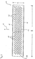
- the scratch coverings according to the invention themselves extending over the entire width of the reel of a card Width, while its length is parallel to the given one Machining route direction is essential is shorter than the width of the drum. Accordingly, it is in progress the processing section facing the drum the processing area of the carrier element usually in essentially rectangular. This can be a reliable attachment the scratch coating on the flat bar are ensured, if the rectangular front on at least one, preferably about two of their longer side edges parallel to the fastening area.
- the inventive Scraps over one with a holding part on the Front of the fastening area of the support element and starting from there towards the back of the support element and, if necessary, extending holding element to be attached to the flat bar of a card, wherein a particularly reliable fastening is ensured, if the holding element in the fastening area of the carrier element has penetrating fastening part.
- a carrier element suitable for such scratch coverings essentially characterized in that there is one for receiving the receiving sections of the scraper wires serving area with a has a substantially flat front, which at least one of its edges merges into a fastening area, the Front with respect to the front of the recording area is offset towards the back of the carrier element.
- a carrier element is preferably made of an elastic Plastic, such as polyvinyl chloride, polyurethane or Polyamide, possibly with appropriate plasticizers.
- carrier elements made of plastic, in particular made of PVC. It can at least increase the strength one, preferably two spaced apart in the thickness direction Tissue inserts can be embedded in the carrier element.
- the scratch coating shown in the drawing is essentially of a carrier element 10 and a number of used in this support member 10.
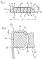
- Scratching wires 30 a synopsis of FIGS. 1 and 5 shows that the carrier element 10 in the manner of a carrier tape with a width B, which corresponds essentially to the width of the cardboard reel, and a much shorter length K in a parallel to the direction of movement indicated by the arrow F in FIG. 5 the lid runs along the specified path Direction is formed. From Fig. 1 it appears that the Carrier element a central receiving area 12 with a comparatively has a large thickness into which the scratch wires 30 are inserted, the opposite of each other on its two Edges each in a fastening area 16 less Fat passes.
- the back 22 of the carrier element essentially formed flat, while the essentially flat and parallel to the rear 22 front 14 of the receiving area receiving the scratch wires 30 12 greater thickness on their two opposite one another Edges over towards the back 22 extending steps 20 in the also substantially flat and approximately parallel to the rear side 22 of the carrier element 10 extending front sides 18 of the fastening area 16. Accordingly, the front faces 18 are the fastening areas 16 with respect to the front 14 of the receiving area 12 in the direction offset in parallel on the rear side 22 of the carrier element 10.
- the edge regions 16 of reduced thickness of the carrier element 10 are available for attaching to attach the scratching surface on a flat bar usually used holding clips Available.
- the difference in height d between the Front 14 of the receiving area 12 and the front 18 the attachment areas 16 an attachment of the retaining clips enables the effectiveness of the over the front 14 of the receiving area projecting and exposed processing sections 36 of the scratch wires 30 leaves uninfluenced.
- FIG. 2 The attachment of retaining clips 50 to the opposite one another Fastening areas 16 of the carrier element 10 is exemplary in .Fig. 2 shown.
- the end of the fastening part facing away from the holding part 52 54 bears against the rear side 22 of the carrier element and thus makes a reliable fastening of the holding clip 50 the carrier element safely.
- the fat d 'of the holding part 52 in a direction perpendicular to the front 18 of the fastening region 16 extending direction is less than the height difference d between the front 14 of the Receiving area 12 and the front 18 of the mounting area 16. This ensures that the effectiveness of the outside of the carrier element 10 exposed processing segments 36 of the scratch wires 30 by attaching the retaining clip 50 is not affected.
- the individual inserted into the receiving area 12 of the support member 10 Scratching wires 30 are formed in a substantially U-shape and have two outer legs 32, one over the back 22 of the support element adjoining connecting section 48 are interconnected.
- Each of the outer legs 32 has one received in the receiving area 12 of the carrier element 10 Receiving section 34 and one over the front 14 of the receiving area 12 projecting, exposed Processing section 36 on.
- the length L of the receiving sections 34 in the direction of the longitudinal axis 31 of the scraper wire 30 much larger than the length 1 of the processing sections 36, the length 1 being approximately 1 mm and the length L approximately 6 mm is.
- the Width b of the individual scratch wires in a direction perpendicular to the direction of movement F and parallel to the front 14 of the recording area 12 running direction is the one in the drawing shown scratching surface about 0.2 mm, while the thickness D of the scratch wire in a perpendicular to that through the longitudinal axis 31 and the width direction spanned plane Direction is approximately 0.48 mm (see FIG. 4). Thereby is guaranteed with sufficient stability of the Scraper wire in a direction parallel to the direction of movement F.
- This machining tip 38 will by two enclosing an acute angle ⁇ of about 16 ° Tip surface segments 40 and 46 formed.
- This in Direction of the lid movement indicated by arrow F. along the specified machining path during a machining process front tip surface segment 46 runs approximately parallel to the longitudinal axis 31 of the scraper wire 30 and closes an acute angle ⁇ of about 12 ° with the machining tip 38 touching surface normals on the front 14 of the recording area w. That the front tip surface segment 46 opposite rear tip surface segment 40 closes with the longitudinal axis 31 of the scraper wheel 30 the acute angle.
- the invention is not explained on the basis of the drawing Embodiment limited. Rather, it is about it thought the angle between the front tip surface segment 46 and the surface normal touching the machining tip 38 on the front 14 of the receiving area 12 in one area to vary between 5 ° and 20 °.
- the angle between the front tip surface segment 46 and the surface normal touching the machining tip 38 on the front 14 of the receiving area 12 in one area to vary between 5 ° and 20 °.
- a square, round or oval cross section become.
- an embodiment is also contemplated in which the front sides 18 of the fastening areas 16 are starting from the side surfaces 24 towards the rear 22 of the support member 10, and so an even more reliable To enable attachment of the retaining clips 50.
Landscapes
- Engineering & Computer Science (AREA)
- Textile Engineering (AREA)
- Preliminary Treatment Of Fibers (AREA)
- Packaging For Recording Disks (AREA)
- Wrappers (AREA)
- Laminated Bodies (AREA)
- Paints Or Removers (AREA)
- Adornments (AREA)
- Details Of Garments (AREA)
Claims (12)
- Garniture de carde pour chapeaux d'une carde, comportant un élément de support (10) et un certain nombre de fils métalliques de carde (30), chaque fois logés par au moins une partie de fixation (34) dans l'élément de support (10), et chacun d'eux présentant au moins une partie de traitement (36) mise à découvert à l'extérieur de l'élément de support (10), la partie de traitement (36) se terminant, à son extrémité située à l'opposé de l'élément de support (10) en une pointe de traitement (38), qui est constituée par deux segments de surface en pointe (40, 46) de la surface limite du fil métallique de carde (30) et qui définissent ensemble un angle aigu (α), au moins l'un de ces segments s'étendant obliquement par rapport à l'axe longitudinal (31) du fil métallique de carde (30) et se transformant, au niveau d'une transition (42) distante de la pointe de traitement (38) en direction de l'axe longitudinal (31) du fil métallique de carde, en un segment arrière de surface limite (44) s'étendant à peu près parallèlement à l'axe longitudinal (31) du fil métallique de carde (30), la transition (42) étant disposée à l'intérieur de l'élément de support (10), caractérisée en ce que l'angle (α) défini entre les segments de surface en pointe est inférieur à 20° et en ce qu'il est, de préférence, d'environ 16°.
- Garniture de carde selon la revendication 1, caractérisée en ce que l'un des segments de surface en pointe (46) s'étend à peu près parallèlement à l'axe longitudinal du fil de carde et en ce qu'il définit, de préférence, un angle aigu (β) compris entre environ 5 et 30° et, de manière préférée, entre environ 5 et 20°, et en ce qu'il est, de manière nettement préférée d'environ 12°, avec une normale à la surface, touchant la pointe de traitement (38), sur le côté avant (14) de l'élément de support (10).
- Garniture de carde selon la revendication 1 ou 2, caractérisée en ce qu'une zone réceptrice (12), de l'élément de support (10), recevant les parties de fixation (34) du fil métallique de carde (30), présente un côté avant (14) sensiblement plat et dirigé vers les parties de traitement (36), la zone réceptrice (12) se transformant, au moins au niveau de l'un de ses bords, en une zone d'attache (16), dont le côté avant (18), dirigé vers les parties de traitement (36), ou bien le côté avant (14) de la zone réceptrice (12) est décalé en direction du côté arrière (22) de l'élément de support (10), dirigé à l'opposé des parties de traitement (36), le côté arrière (22) de l'élément de support (10) étant disposé, de préférence, dans un plan s'étendant à peu près parallèlement au côté avant (14) de la zone réceptrice (12), et le côté avant (18) de la zone d'attache (16) étant disposé dans un plan s'étendant à peu près parallèlement au côté avant (14) de la zone réceptrice (12).
- Garniture de carde selon la revendication 3, caractérisée par un élément de retenue (50), qui est appliqué par une partie de retenue (52) contre le côté avant (18) de la zone d'attache (16) et qui s'étend, à partir de là, en direction du côté arrière (22) de l'élément de support (10) et, le cas échéant, au-delà de celui-ci, lequel élément de retenue sert à maintenir la garniture de carde contre une barre de recouvrement, et l'élément de retenue (50) présentant, de préférence, une partie d'attache (54) qui traverse la zone d'attache (16).
- Garniture de carde selon l'une des revendications précédentes, caractérisée en ce l'élément de support consiste essentiellement en une matière plastique, notamment en du PVC.
- Garniture de carde selon la revendication 5, caractérisée en ce qu'au moins une couche, et de préférence au moins deux couches intermédiaires de textile, distantes l'une de l'autre dans le sens de l'épaisseur, sont insérées dans l'élément de support.
- Garniture de carde selon l'une des revendications précédentes, caractérisée en ce que, pour au moins l'un des fils métalliques de carde (30), la partie de fixation (34) est au moins de la même longueur que la partie de traitement (36) tandis que, de préférence, pour au moins l'un des fils métalliques de carde (30), le rapport de la longueur (L) de la partie de fixation (34) à la longueur (l) de la partie de traitement (36) est d'au moins 3 : 1 et, de manière particulièrement préférée, d'au moins 5 : 1.
- Garniture de carde selon la revendication 7, caractérisée en ce que, pour au moins l'un des fils métalliques de carde (30), la longueur (l) de la partie de traitement (36) est inférieure à 3 mm, de préférence inférieure à 2 mm et, de manière particulièrement préférée, inférieure à 1,5 mm.
- Garniture de carde selon la revendication 8, caractérisée en ce que la longueur (l) de la partie de traitement est d'environ 1 mm.
- Garniture de carde selon l'une des revendications précédentes, caractérisée en ce que le fil métallique de carde présente, dans une direction s'étendant perpendiculairement à son axe longitudinal, une largeur d'au moins 0,2 mm et, de préférence, d'au moins 0, 4 mm.
- Garniture de carde selon la revendication 10, caractérisée en ce que le rapport de l'épaisseur (D) à la largeur (b) du fil métallique de carde est inférieur à 3.
- Garniture de carde selon la revendication 11, caractérisée en ce que le fil métallique de carde présente, dans un plan de coupe s'étendant perpendiculairement à son axe longitudinal (31), une section transversale sensiblement carrée.
Applications Claiming Priority (2)
| Application Number | Priority Date | Filing Date | Title |
|---|---|---|---|
| DE19901010 | 1999-01-13 | ||
| DE19901010 | 1999-01-13 |
Publications (3)
| Publication Number | Publication Date |
|---|---|
| EP1020548A2 EP1020548A2 (fr) | 2000-07-19 |
| EP1020548A3 EP1020548A3 (fr) | 2001-04-18 |
| EP1020548B1 true EP1020548B1 (fr) | 2003-12-17 |
Family
ID=7894121
Family Applications (1)
| Application Number | Title | Priority Date | Filing Date |
|---|---|---|---|
| EP00100677A Expired - Lifetime EP1020548B1 (fr) | 1999-01-13 | 2000-01-13 | Garniture de carde pour chapeaux d'une machine de cardage |
Country Status (7)
| Country | Link |
|---|---|
| US (1) | US6170124B1 (fr) |
| EP (1) | EP1020548B1 (fr) |
| KR (1) | KR20000062455A (fr) |
| AT (1) | ATE256773T1 (fr) |
| BR (1) | BR0000050A (fr) |
| DE (1) | DE50004754D1 (fr) |
| TW (1) | TW592222U (fr) |
Families Citing this family (6)
| Publication number | Priority date | Publication date | Assignee | Title |
|---|---|---|---|---|
| WO2002068739A1 (fr) * | 2001-02-24 | 2002-09-06 | Maschinenfabrik Rieter Ag | Pince pour bandes de garniture |
| USD562358S1 (en) * | 2006-03-18 | 2008-02-19 | Trutzschler Gmbh & Co. Kg | Flat and clothing for textile machine |
| CN101498065B (zh) * | 2009-03-03 | 2011-01-19 | 金轮科创股份有限公司 | 盖板针布植针机 |
| CH702329A1 (de) | 2009-12-01 | 2011-06-15 | Rieter Ag Maschf | Wanderdeckel. |
| CH706587A1 (de) | 2012-06-04 | 2013-12-13 | Graf & Co Ag | Garniturträger. |
| CN108441991B (zh) * | 2018-05-22 | 2023-09-12 | 海盐兴达纺针科技有限公司 | 一种梳针更换方便的针板 |
Family Cites Families (13)
| Publication number | Priority date | Publication date | Assignee | Title |
|---|---|---|---|---|
| US129662A (en) * | 1872-07-23 | Improvement in teeth for carding-machines | ||
| US401991A (en) * | 1889-04-23 | Petebs | ||
| US1293504A (en) * | 1915-04-13 | 1919-02-04 | Herbert Midgley | Foundation for card-clothing. |
| GB347704A (en) * | 1930-01-28 | 1931-04-28 | Alfred Law Mowat | Improvements in card clothing |
| US2488442A (en) * | 1948-03-10 | 1949-11-15 | Jr Edwin Allen Snape | Card clothing |
| US2937412A (en) * | 1955-11-07 | 1960-05-24 | John D Hollingsworth | Card clothing |
| FR1189593A (fr) * | 1958-01-08 | 1959-10-05 | Perfectionnement aux garnitures de cardes | |
| US3151362A (en) * | 1959-06-18 | 1964-10-06 | Lemahieu Antoinette M Cornelie | Clothings for flats of carding machines |
| US3290729A (en) * | 1961-08-04 | 1966-12-13 | Deering Milliken Res Corp | Card clothing |
| GB1474889A (en) | 1973-10-04 | 1977-05-25 | English Card Clothing | Card clothing |
| DE2825506A1 (de) | 1978-06-10 | 1979-12-20 | Truetzschler & Co | Kardiergarnitur |
| CH636134A5 (de) | 1979-04-20 | 1983-05-13 | Graf & Co Ag | Kratzentraeger fuer kardenbelaege. |
| DE3801031A1 (de) * | 1987-10-05 | 1989-04-13 | Sulzer Morat Gmbh | Kardenrad fuer eine strickmaschine zur herstellung von strickwaren mit eingekaemmten fasern |
-
2000
- 2000-01-10 TW TW092222788U patent/TW592222U/zh unknown
- 2000-01-12 BR BR0000050-7A patent/BR0000050A/pt not_active IP Right Cessation
- 2000-01-12 US US09/481,789 patent/US6170124B1/en not_active Expired - Fee Related
- 2000-01-12 KR KR1020000001295A patent/KR20000062455A/ko not_active Withdrawn
- 2000-01-13 EP EP00100677A patent/EP1020548B1/fr not_active Expired - Lifetime
- 2000-01-13 DE DE50004754T patent/DE50004754D1/de not_active Expired - Fee Related
- 2000-01-13 AT AT00100677T patent/ATE256773T1/de not_active IP Right Cessation
Also Published As
| Publication number | Publication date |
|---|---|
| DE50004754D1 (de) | 2004-01-29 |
| ATE256773T1 (de) | 2004-01-15 |
| EP1020548A2 (fr) | 2000-07-19 |
| BR0000050A (pt) | 2000-09-05 |
| TW592222U (en) | 2004-06-11 |
| US6170124B1 (en) | 2001-01-09 |
| EP1020548A3 (fr) | 2001-04-18 |
| KR20000062455A (ko) | 2000-10-25 |
Similar Documents
| Publication | Publication Date | Title |
|---|---|---|
| EP1069224A1 (fr) | Aiguille de feutrage | |
| EP1136599B1 (fr) | Fil en dents de scie | |
| DE2539603C3 (de) | Krempel mit mindestens einer Arbeiter- und Wenderwalze | |
| EP0905293B1 (fr) | Chapeau de machine de cardage | |
| CH711742A1 (de) | Garniturdraht. | |
| EP1736576A2 (fr) | Dispositif pour nettoyer un segment de peigne d'une machine de peignage | |
| EP1020548A2 (fr) | Garniture de carde pour chapeaux d'une machine de cardage | |
| DE2407074A1 (de) | Breithalter | |
| DE10247215B4 (de) | Sägezahndraht | |
| EP3117033A1 (fr) | Fil métallique de garniture de carde et procédé de fabrication de nappes de fibres discontinues | |
| EP1411157B1 (fr) | Carde avec garniture de chapeaux présentant des pointes meulées | |
| EP1227179B1 (fr) | Garniture de carde | |
| DE1785241B2 (de) | Vorrichtung zum abnehmen des faserflors vom abnehmer der karde einer karde oder krempel | |
| DE10203853C5 (de) | Deckelgarnitur für einen Kardendeckel | |
| DE60109881T2 (de) | System zum Antreiben der Deckel, und Reinigen der Führungselemente der Deckel, in einer Deckelkarde | |
| CH685766A5 (de) | Sägezahnwalze mit schraubenlinienförmig verlaufender Sägezahngarnitur. | |
| DE102006006944A1 (de) | Vorrichtung an einer Karde für Baumwolle, Chemiefasern u. dgl., bei der mindestens ein Deckelstab mit einer Deckelgarnitur vorhanden ist. | |
| DE2102478A1 (en) | Wire screen joint - with oblique disposition wrt direction of motion to reduce flapping and starting torque | |
| EP1004692B1 (fr) | Procédé pour faire fonctionner une machine de cardage et chapeaux pour la mise en oeuvre de ce procédé | |
| CH698224B1 (de) | Vorrichtung an einer Karde für Baumwolle oder Chemiefasern. | |
| EP1333113A1 (fr) | Garniture à dents de scie pour le peigne d'une peigneuse | |
| DE10323359A1 (de) | Mehrteiliger Garniturstreifen-Clip | |
| EP1586683B1 (fr) | Ruban à pinces pour métier à tisser à pinces et métier à tisser à pinces | |
| WO2008144950A1 (fr) | Garniture flexible | |
| CH702329A1 (de) | Wanderdeckel. |
Legal Events
| Date | Code | Title | Description |
|---|---|---|---|
| PUAI | Public reference made under article 153(3) epc to a published international application that has entered the european phase |
Free format text: ORIGINAL CODE: 0009012 |
|
| AK | Designated contracting states |
Kind code of ref document: A2 Designated state(s): AT BE CH CY DE DK ES FI FR GB GR IE IT LI LU MC NL PT SE |
|
| AX | Request for extension of the european patent |
Free format text: AL;LT;LV;MK;RO;SI |
|
| PUAL | Search report despatched |
Free format text: ORIGINAL CODE: 0009013 |
|
| AK | Designated contracting states |
Kind code of ref document: A3 Designated state(s): AT BE CH CY DE DK ES FI FR GB GR IE IT LI LU MC NL PT SE |
|
| AX | Request for extension of the european patent |
Free format text: AL;LT;LV;MK;RO;SI |
|
| 17P | Request for examination filed |
Effective date: 20010523 |
|
| AKX | Designation fees paid |
Free format text: AT BE CH CY DE DK ES FI FR GB GR IE IT LI LU MC NL PT SE |
|
| 17Q | First examination report despatched |
Effective date: 20021101 |
|
| GRAH | Despatch of communication of intention to grant a patent |
Free format text: ORIGINAL CODE: EPIDOS IGRA |
|
| GRAS | Grant fee paid |
Free format text: ORIGINAL CODE: EPIDOSNIGR3 |
|
| GRAA | (expected) grant |
Free format text: ORIGINAL CODE: 0009210 |
|
| AK | Designated contracting states |
Kind code of ref document: B1 Designated state(s): AT BE CH CY DE DK ES FI FR GB GR IE IT LI LU MC NL PT SE |
|
| PG25 | Lapsed in a contracting state [announced via postgrant information from national office to epo] |
Ref country code: IT Free format text: LAPSE BECAUSE OF FAILURE TO SUBMIT A TRANSLATION OF THE DESCRIPTION OR TO PAY THE FEE WITHIN THE PRESCRIBED TIME-LIMIT;WARNING: LAPSES OF ITALIAN PATENTS WITH EFFECTIVE DATE BEFORE 2007 MAY HAVE OCCURRED AT ANY TIME BEFORE 2007. THE CORRECT EFFECTIVE DATE MAY BE DIFFERENT FROM THE ONE RECORDED. Effective date: 20031217 Ref country code: FI Free format text: LAPSE BECAUSE OF FAILURE TO SUBMIT A TRANSLATION OF THE DESCRIPTION OR TO PAY THE FEE WITHIN THE PRESCRIBED TIME-LIMIT Effective date: 20031217 Ref country code: IE Free format text: LAPSE BECAUSE OF FAILURE TO SUBMIT A TRANSLATION OF THE DESCRIPTION OR TO PAY THE FEE WITHIN THE PRESCRIBED TIME-LIMIT Effective date: 20031217 Ref country code: CY Free format text: LAPSE BECAUSE OF FAILURE TO SUBMIT A TRANSLATION OF THE DESCRIPTION OR TO PAY THE FEE WITHIN THE PRESCRIBED TIME-LIMIT Effective date: 20031217 Ref country code: FR Free format text: LAPSE BECAUSE OF FAILURE TO SUBMIT A TRANSLATION OF THE DESCRIPTION OR TO PAY THE FEE WITHIN THE PRESCRIBED TIME-LIMIT Effective date: 20031217 Ref country code: NL Free format text: LAPSE BECAUSE OF FAILURE TO SUBMIT A TRANSLATION OF THE DESCRIPTION OR TO PAY THE FEE WITHIN THE PRESCRIBED TIME-LIMIT Effective date: 20031217 Ref country code: GB Free format text: LAPSE BECAUSE OF FAILURE TO SUBMIT A TRANSLATION OF THE DESCRIPTION OR TO PAY THE FEE WITHIN THE PRESCRIBED TIME-LIMIT Effective date: 20031217 |
|
| REG | Reference to a national code |
Ref country code: GB Ref legal event code: FG4D Free format text: NOT ENGLISH |
|
| REG | Reference to a national code |
Ref country code: CH Ref legal event code: EP Ref country code: CH Ref legal event code: NV Representative=s name: DR. LUSUARDI AG |
|
| PG25 | Lapsed in a contracting state [announced via postgrant information from national office to epo] |
Ref country code: LU Free format text: LAPSE BECAUSE OF NON-PAYMENT OF DUE FEES Effective date: 20040113 Ref country code: AT Free format text: LAPSE BECAUSE OF NON-PAYMENT OF DUE FEES Effective date: 20040113 |
|
| REG | Reference to a national code |
Ref country code: IE Ref legal event code: FG4D Free format text: GERMAN |
|
| REF | Corresponds to: |
Ref document number: 50004754 Country of ref document: DE Date of ref document: 20040129 Kind code of ref document: P |
|
| PG25 | Lapsed in a contracting state [announced via postgrant information from national office to epo] |
Ref country code: MC Free format text: LAPSE BECAUSE OF NON-PAYMENT OF DUE FEES Effective date: 20040131 Ref country code: LI Free format text: LAPSE BECAUSE OF NON-PAYMENT OF DUE FEES Effective date: 20040131 Ref country code: BE Free format text: LAPSE BECAUSE OF NON-PAYMENT OF DUE FEES Effective date: 20040131 Ref country code: CH Free format text: LAPSE BECAUSE OF NON-PAYMENT OF DUE FEES Effective date: 20040131 |
|
| PG25 | Lapsed in a contracting state [announced via postgrant information from national office to epo] |
Ref country code: DK Free format text: LAPSE BECAUSE OF FAILURE TO SUBMIT A TRANSLATION OF THE DESCRIPTION OR TO PAY THE FEE WITHIN THE PRESCRIBED TIME-LIMIT Effective date: 20040317 Ref country code: GR Free format text: LAPSE BECAUSE OF FAILURE TO SUBMIT A TRANSLATION OF THE DESCRIPTION OR TO PAY THE FEE WITHIN THE PRESCRIBED TIME-LIMIT Effective date: 20040317 Ref country code: SE Free format text: LAPSE BECAUSE OF FAILURE TO SUBMIT A TRANSLATION OF THE DESCRIPTION OR TO PAY THE FEE WITHIN THE PRESCRIBED TIME-LIMIT Effective date: 20040317 |
|
| PG25 | Lapsed in a contracting state [announced via postgrant information from national office to epo] |
Ref country code: ES Free format text: LAPSE BECAUSE OF FAILURE TO SUBMIT A TRANSLATION OF THE DESCRIPTION OR TO PAY THE FEE WITHIN THE PRESCRIBED TIME-LIMIT Effective date: 20040328 |
|
| NLV1 | Nl: lapsed or annulled due to failure to fulfill the requirements of art. 29p and 29m of the patents act | ||
| GBV | Gb: ep patent (uk) treated as always having been void in accordance with gb section 77(7)/1977 [no translation filed] |
Effective date: 20031217 |
|
| REG | Reference to a national code |
Ref country code: IE Ref legal event code: FD4D |
|
| BERE | Be: lapsed |
Owner name: GRAF + CIE A.G. Effective date: 20040131 |
|
| PG25 | Lapsed in a contracting state [announced via postgrant information from national office to epo] |
Ref country code: DE Free format text: LAPSE BECAUSE OF NON-PAYMENT OF DUE FEES Effective date: 20040803 |
|
| REG | Reference to a national code |
Ref country code: CH Ref legal event code: PL |
|
| PLBE | No opposition filed within time limit |
Free format text: ORIGINAL CODE: 0009261 |
|
| STAA | Information on the status of an ep patent application or granted ep patent |
Free format text: STATUS: NO OPPOSITION FILED WITHIN TIME LIMIT |
|
| 26N | No opposition filed |
Effective date: 20040920 |
|
| EN | Fr: translation not filed | ||
| PG25 | Lapsed in a contracting state [announced via postgrant information from national office to epo] |
Ref country code: PT Free format text: LAPSE BECAUSE OF NON-PAYMENT OF DUE FEES Effective date: 20040517 |