EP1069224A1 - Aiguille de feutrage - Google Patents
Aiguille de feutrage Download PDFInfo
- Publication number
- EP1069224A1 EP1069224A1 EP00109536A EP00109536A EP1069224A1 EP 1069224 A1 EP1069224 A1 EP 1069224A1 EP 00109536 A EP00109536 A EP 00109536A EP 00109536 A EP00109536 A EP 00109536A EP 1069224 A1 EP1069224 A1 EP 1069224A1
- Authority
- EP
- European Patent Office
- Prior art keywords
- diameter
- needle
- transition
- working part
- clamping part
- Prior art date
- Legal status (The legal status is an assumption and is not a legal conclusion. Google has not performed a legal analysis and makes no representation as to the accuracy of the status listed.)
- Granted
Links
- 238000009950 felting Methods 0.000 title claims abstract description 23
- 230000007704 transition Effects 0.000 claims abstract description 62
- 239000000835 fiber Substances 0.000 description 27
- 238000004140 cleaning Methods 0.000 description 6
- 239000000463 material Substances 0.000 description 5
- 238000004519 manufacturing process Methods 0.000 description 3
- 238000000034 method Methods 0.000 description 3
- 230000008569 process Effects 0.000 description 3
- 230000035508 accumulation Effects 0.000 description 2
- 238000009825 accumulation Methods 0.000 description 2
- 230000007423 decrease Effects 0.000 description 2
- 239000004745 nonwoven fabric Substances 0.000 description 2
- 230000009467 reduction Effects 0.000 description 2
- 230000008901 benefit Effects 0.000 description 1
- 230000003247 decreasing effect Effects 0.000 description 1
- 230000008021 deposition Effects 0.000 description 1
- 238000005137 deposition process Methods 0.000 description 1
- 230000004907 flux Effects 0.000 description 1
- 238000003780 insertion Methods 0.000 description 1
- 230000037431 insertion Effects 0.000 description 1
- 239000002557 mineral fiber Substances 0.000 description 1
- 239000000203 mixture Substances 0.000 description 1
- 239000007787 solid Substances 0.000 description 1
- 238000003860 storage Methods 0.000 description 1
- 239000012209 synthetic fiber Substances 0.000 description 1
- 229920002994 synthetic fiber Polymers 0.000 description 1
Images


Classifications
-
- D—TEXTILES; PAPER
- D04—BRAIDING; LACE-MAKING; KNITTING; TRIMMINGS; NON-WOVEN FABRICS
- D04H—MAKING TEXTILE FABRICS, e.g. FROM FIBRES OR FILAMENTARY MATERIAL; FABRICS MADE BY SUCH PROCESSES OR APPARATUS, e.g. FELTS, NON-WOVEN FABRICS; COTTON-WOOL; WADDING ; NON-WOVEN FABRICS FROM STAPLE FIBRES, FILAMENTS OR YARNS, BONDED WITH AT LEAST ONE WEB-LIKE MATERIAL DURING THEIR CONSOLIDATION
- D04H18/00—Needling machines
- D04H18/02—Needling machines with needles
Definitions
- the invention relates to a needle with the features of the preamble of claim 1 or of the claim 2nd
- Loose and disorganized are made during felt production superimposed fibers by a machine between a multi-perforated scraper plate and one too perforated bed plate. This mixture of fibers is repeated with a larger number of special Pierced needles (felting needles). The felting needles work thereby binding the fiber to one another so that the Gradually compacted web and ultimately a solid Felt is made.
- the fibers come apart from natural fibers and synthetic fibers also use recycled fibers that are used in usually have an increased tendency to join fix the needles and form deposits.
- Deposits form after a certain period of time the machine for making the felt.
- the deposits can clog the needles to such an extent that the Needles are no longer able to pass through the holes of the To penetrate the scraper plate. This will cause deposits Broken needles and lost production.
- the air flow between negatively affected the needles with the result that the deposits accelerate.
- For needle cleaning production must be interrupted. When cleaning the needle needle breakage occurs frequently.
- the material is solidified during the needle process. To Beginning, i.e. when pinning, the material is relative loose and voluminous. Penetrates the needle with its shaft section or their intermediate area in the material, it creates holes with shaft diameter or the diameter of the intermediate section that is larger than that Diameter of the working part. This results in a bad one Surface quality of the felt.
- DE 1760440 C3 describes felting needles with a long one known straight shaft, which at its upper end to the Is angled in a needle board.
- the shaft tapers at its other end to a reduced one Cross-section and is provided with hooks.
- This Section forms a working part which is used to matt the Nonwoven serves.
- the transition between the work part and the remaining shaft serving as a clamping part is relative steep.
- DE 3704471 A1 describes a device for needling a mineral fiber fleece known.
- the one on a needle board held felting needles extend parallel to each other away from the needle board through corresponding openings one Scraper plate. Between this and a bed plate, the also has openings for the felting needles is a Formed gap through which the nonwoven fabric is passed.
- the felting needles have a cylindrical, angled top and relatively thick shaft, one section of which is held in the needle board. Between the clamping part and the serrated working part is a transition area trained, the length of which is hardly greater than that Diameter of the shaft area.
- a fork needle is known from DE-OS 2222881, which has a toothless work area. This connects to one another via a conical intermediate area cylindrical shaft. The working part is on his The outside is smooth and only on his Provide the free end with a mouth-like fork. Depending on Embodiment may have a more or less steep transition area be provided in the form of a cone.
- Fork needles are used to consolidate nonwovens to structure in a follow-up process. You tend because of little of the smooth, toothless flanks of the working part to detach fibers from the fiber structure and take them with you.
- Felting needles with a serrated working part tend to come off fibers pulled out of the fiber structure on their shaft accumulate.
- the shaft is enough when needling the fibers partly in the work area between the scraper plate and Bed plate.
- the fibers that are pulled out form deposits in the form of fiber rings, which differ from the relatively thin Working part on the short transition area to the cylindrical shaft area between the needle board and push the scraper plate. In doing so, they are expanded and tightened.
- Exceed these deposits tolerable measure is the insertion of the needles in the Fleece hampers because the needle board is no longer close enough can be brought up to the scraper plate. There are therefore from time to time depending on the nonwoven material used Cleaning actions required. Because of the large number the needle held on a needle board is one Cleaning laborious and time consuming.
- the needle according to the invention is characterized in that that between the toothed working part and the Toothed clamping part is a relatively slim transition part or transition area is formed, at least has a range in which the diameter of the shaft diameter to the diameter of the working part gradually decreased.
- the length of this area if necessary also be divided into several sections overall is at least twice as long as that Length of the toothed working part.
- the transition part preferably takes the whole Space between the needle board and the respective work part a (claim 2). There is a lean transition which leads to less deposits on the needle form.
- the working part of the Needle can be made slimmer than conventional ones Needles.
- the transition is preferably longer 11 better still 20 mm (claim 3).
- the invention Needle can be felt needles with single, double or triple Replace diameter reduction. So that drops variety of types to be provided by the needle manufacturer.
- Another advantage is that the shaft area, the when needling into the work area between the scraper plate and bed plate arrives, a smaller diameter compared to conventional needles. Thereby the openings created by the shaft area in the manufactured felt smaller in diameter. Thus improved the surface quality of the felt.
- the transition part is preferably conical in one continuous part.
- the cone can be a straight one Be a circular truncated cone. This means a generatrix this area is a straight line.
- the Cone can also be formed by a non-straight cone. A generatrix of the transition part is then arcuate.
- the working part and the clamping part is preferably arranged coaxially with one another. If necessary, however, can also deviate from this become. It is also preferred that the working part has a has constant diameter and also preferably without changing the diameter smooth to the transition part connects.
- the transition part takes the whole Space between the needle board and the working part.
- the Total length of the transition part can be due to the needle dimensions less than twice the length of the part his.
- the needle consists of three areas: Working part, transition part and shaft part, the complete sitting in the needle board.
- transition part is longer is intended as the thickness of the for attaching the needles Needle boards. Regardless of the total length of the The transition part begins with the transition part according to the invention Embodiment according to claim 2 immediately on the needle board.
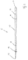
- Figure 1 is a device 1 for needling a Fleece illustrated. Belongs to device 1 a needle board 2, which is driven, for example, by an eccentric is and a reciprocating motion in one direction illustrated by an arrow 3.
- the needle board 2 has openings 4 for mounting and storage of needles 5 on.
- the needles 5 extend in the Distance and parallel to each other away from the needle board 2. They protrude through stripping openings 6 in a stripping plate 7 are formed. This is at some distance arranged to a bed plate 8 and lays with this an intermediate space 9, through the loose and disordered fibers lying in one in FIG. 1 by an arrow 11 designated direction. In the further course these fibers become by the up and down movement of the needles 5 consolidated into a fleece.
- Openings 12 are provided in the bed plate 8, each having an opening 12 of the bed plate 8 with a Opening 6 of the scraper plate 7 is aligned.
- the needles 5 are constructed to match one another. They each have one held in the needle board 2 Clamping part 14 and one with barbs or hooks 15 provided working part 16. Between the clamping part 14 and the working part 16 is a transition part 17 arranged. The transition part 17 extends from the Clamping part 14 up to the working part 16, being in immediate vicinity of the needle board 2 begins.
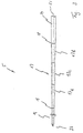
- FIG 2 is a needle 5 to illustrate the Proportions shown.
- the transition part 17 decreases the diameter of the larger one, at the transition point 18 value to be measured at a lower value, which at a transition point 19 is to be measured, at which the working part 16 begins.
- the transition part 17 is coaxial with a longitudinal axis 21 of the needle 5 arranged and forms a total a contiguous area for customization of the diameter.
- the clamping part 14 and Working part 16 arranged coaxially to the longitudinal axis 21. The diameter decreases along the longitudinal axis 21 of the transition part 17 steady and linear.
- the between the Practice crossing points 18, 19 length of the transition part to be measured 17 is at least twice the length of the Working part 16, i.e. the distance of the transition point 19 from one formed at the free end of the needle 5 Tip 22. This makes the transition part very slim and long. It has no levels or paragraphs.
- the device 1 works as follows:
- the needle board 2 is in quick succession moved back and forth in the direction of arrow 3, that the needles 5 periodically clear the space 9 and puncture. Solidify the hooks 15 of the working parts 16 the individual fibers form a fleece. At this process still exists, especially for the first needles coming into contact with unconsolidated fibers the risk that individual fiber filaments are taken away and are pulled through the stripping openings 6 and on deposit the needle 5. With the needles 5 according to the invention this tendency is due to the long and lean training the transition parts 17 counteracted. The needles 5 draw at least some nonwoven materials, and in particular with recycled fibers fewer fibers due to the Scraper openings 6.
- FIG 3 is a slightly modified embodiment the needle 5 illustrates.
- the one from the transition part 17 formed area is in two sub-areas 17a, 17b, in which the diameter of the needle 5 reduced from the shaft diameter to the working part diameter.
- the sub-area 17a borders on the transition point 19, while the section 17b to the transition point 18 borders.
- Between the partial areas 17a, 17b an intermediate cylindrical portion 17c is formed.
- this also applies advantageously the transition part 17 immediately after the needle board 2 begins, i.e. that the transition point 18 aligned with the underside of the needle board 2.
- the subareas 17a, 17b, in which the tapering of the needle 5 taken together have a length that is the same or greater than twice the length of the working part 16, i.e. the distance between the transition point 19 and the tip 22.
- the latter applies accordingly to those in Figures 4 and Figure 5 illustrates embodiment of the needle 5. Die The above description applies accordingly, but with an exception.
- the partial areas 17a, 17b each lie on the mantle of a narrow cone, i.e. the diameter takes on the tip 22 in these partial areas 17a, 17b down.
- the diameter reduction is at 4 linear for the partial region 17a, not for section 17b.
- the diameter increases to the top starting from the transition point 18 initially stronger and then less strong.
- the cone is therefore curvilinear.
- Such a cone can also be used instead of the cone in section 17a or in the embodiment of Figure 2 instead of the straight slim truncated cone is formed in the transition part 17 his.
- transition part 17 is provided which is designed as a long, slender truncated cone.
- the length this transition part 17 is at least twice as long like the working part. This results in a very slim transition area, which tends little to fibers pull out of the fleece and collect. Should nevertheless form fiber deposits, these are easy to remove.
Landscapes
- Engineering & Computer Science (AREA)
- Textile Engineering (AREA)
- Nonwoven Fabrics (AREA)
Applications Claiming Priority (2)
| Application Number | Priority Date | Filing Date | Title |
|---|---|---|---|
| US09/352,369 US6233797B1 (en) | 1999-07-13 | 1999-07-13 | Felt needle |
| US352369 | 1999-07-13 |
Publications (2)
| Publication Number | Publication Date |
|---|---|
| EP1069224A1 true EP1069224A1 (fr) | 2001-01-17 |
| EP1069224B1 EP1069224B1 (fr) | 2007-06-27 |
Family
ID=23384854
Family Applications (1)
| Application Number | Title | Priority Date | Filing Date |
|---|---|---|---|
| EP00109536A Expired - Lifetime EP1069224B1 (fr) | 1999-07-13 | 2000-05-04 | Aiguille de feutrage |
Country Status (5)
| Country | Link |
|---|---|
| US (1) | US6233797B1 (fr) |
| EP (1) | EP1069224B1 (fr) |
| JP (1) | JP3566187B2 (fr) |
| DE (1) | DE50014437D1 (fr) |
| ES (1) | ES2288815T3 (fr) |
Cited By (7)
| Publication number | Priority date | Publication date | Assignee | Title |
|---|---|---|---|---|
| FR2885621A1 (fr) * | 2005-05-16 | 2006-11-17 | Duflot Ind Sa | Aiguille sans barre pour aiguilleteuse, son utilisation et produit complexe aiguillete et perfore obtenu |
| EP1953287A1 (fr) * | 2007-02-02 | 2008-08-06 | Groz-Beckert KG | Procédé et dispositif destinés à l'implantation de planches à pointes pour machines de feutrage |
| CN103938369A (zh) * | 2014-04-11 | 2014-07-23 | 吴江龙升纺织有限公司 | 一种纤网加固装置 |
| RU2815026C2 (ru) * | 2022-08-16 | 2024-03-11 | Общество с ограниченной ответственностью "Предприятие нетканых материалов" | Способ производства материала геотекстильного |
| DE102023119894A1 (de) | 2023-07-27 | 2025-01-30 | Voith Patent Gmbh | Verfahren und Vorrichtung |
| WO2025021636A1 (fr) | 2023-07-27 | 2025-01-30 | Voith Patent Gmbh | Procédé et feutre |
| EP4663826A1 (fr) * | 2024-06-13 | 2025-12-17 | Groz-Beckert KG | Aiguille de feutre, plaque à aiguilles pour une machine de feutre et procédé d'introduction d'une aiguille de feutre dans une plaque à aiguilles |
Families Citing this family (19)
| Publication number | Priority date | Publication date | Assignee | Title |
|---|---|---|---|---|
| GB0402131D0 (en) * | 2004-01-30 | 2004-03-03 | Isis Innovation | Delivery method |
| DE102004037716B4 (de) * | 2004-08-04 | 2009-04-02 | Groz-Beckert Kg | Nachbehandlungsnadel für textile Flächengebilde |
| US20070044696A1 (en) * | 2005-08-31 | 2007-03-01 | Chih-Po Yang | Needle for stereographic embroidery |
| DE502005007017D1 (de) * | 2005-12-27 | 2009-05-14 | Groz Beckert Kg | Filznadel |
| EP2218814B1 (fr) * | 2009-02-12 | 2011-05-04 | Groz-Beckert KG | Aiguille pour une machine textile |
| US8251262B2 (en) * | 2009-08-12 | 2012-08-28 | Timothy Peckels | Volume metered pour spout |
| AU2012323782B2 (en) | 2011-10-12 | 2017-04-06 | Vaxxas Pty Limited | Delivery device |
| WO2016123665A1 (fr) | 2015-02-02 | 2016-08-11 | Vaxxas Pty Limited | Applicateur à réseau de microprojections et procédé |
| WO2017045031A1 (fr) | 2015-09-18 | 2017-03-23 | Vaxxas Pty Limited | Réseaux de micro-saillies comportant des micro-saillies ayant des profils à surface élevée |
| CA2999538A1 (fr) | 2015-09-28 | 2017-04-06 | Vaxxas Pty Limited | Reseau de microsaillies ayant des proprietes de penetration de la peau ameliorees et procedes associes |
| ES2960937T3 (es) | 2017-03-31 | 2024-03-07 | Vaxxas Pty Ltd | Dispositivo y método para recubrir superficies |
| US11175128B2 (en) | 2017-06-13 | 2021-11-16 | Vaxxas Pty Limited | Quality control of substrate coatings |
| EP4473998A3 (fr) | 2017-08-04 | 2025-02-26 | Vaxxas Pty Limited | Actionneur à stockage d'énergie mécanique élevé compact et à force de déclenchement faible pour l'administration de patchs à réseaux de microprojections (prm) |
| US12297571B2 (en) | 2022-10-31 | 2025-05-13 | Rohr, Inc. | Systems and methods for spray cleaning needles for through thickness reinforcement of resin-infused fabrics |
| US12404616B2 (en) | 2022-10-31 | 2025-09-02 | Rohr, Inc. | Systems and methods for robotic arm end effector for tailored through thickness reinforcement |
| US12297572B2 (en) * | 2022-10-31 | 2025-05-13 | Rohr, Inc. | Systems and methods for self-cleaning needles for through thickness reinforcement of resin-infused fabrics |
| US12545628B2 (en) | 2023-03-17 | 2026-02-10 | Rtx Corporation | Sheathed metallic needles for producing z-channels in fibrous preforms |
| US20240308922A1 (en) * | 2023-03-17 | 2024-09-19 | Raytheon Technologies Corporation | Tooling for producing z-channels in ceramic fiber preforms |
| US12589525B2 (en) | 2024-01-16 | 2026-03-31 | Goodrich Corporation | In-situ compaction during z-fiber reinforcement of dry fiber preforms |
Citations (6)
| Publication number | Priority date | Publication date | Assignee | Title |
|---|---|---|---|---|
| US2857650A (en) * | 1954-03-10 | 1958-10-28 | Du Pont | Needle |
| CH343353A (de) * | 1954-03-10 | 1959-12-31 | Du Pont | Verfahren zum Ineinanderverwirren von Fasern durch Einstechen von Nadeln in Stoffe |
| GB1227986A (fr) * | 1967-06-01 | 1971-04-15 | ||
| US3753412A (en) * | 1971-12-02 | 1973-08-21 | Torrington Co | Selectively hardened needles |
| US3844004A (en) * | 1973-09-20 | 1974-10-29 | E Foster | Felting needle |
| US4131978A (en) * | 1977-11-09 | 1979-01-02 | The Singer Company | Felting needle |
Family Cites Families (6)
| Publication number | Priority date | Publication date | Assignee | Title |
|---|---|---|---|---|
| US2883585A (en) * | 1954-06-15 | 1959-04-21 | Westinghouse Electric Corp | Circuit breaker |
| DE1265426B (de) * | 1964-04-15 | 1968-04-04 | J J Marx Fa | Nadelbrett fuer Nadelfilzmaschinen und Verfahren zu seiner Bestueckung mit Nadeln |
| US3347192A (en) * | 1965-05-24 | 1967-10-17 | Union Special Machine Co | Sewing machine needle |
| US3542632A (en) * | 1969-02-28 | 1970-11-24 | Standard Oil Co | Fibrillated fabrics and a process for the preparation thereof |
| US3877120A (en) * | 1970-02-20 | 1975-04-15 | Toray Industries | Needle board |
| US3727276A (en) * | 1971-04-06 | 1973-04-17 | E Foster | Felting needle |
-
1999
- 1999-07-13 US US09/352,369 patent/US6233797B1/en not_active Expired - Lifetime
-
2000
- 2000-05-04 EP EP00109536A patent/EP1069224B1/fr not_active Expired - Lifetime
- 2000-05-04 ES ES00109536T patent/ES2288815T3/es not_active Expired - Lifetime
- 2000-05-04 DE DE50014437T patent/DE50014437D1/de not_active Expired - Lifetime
- 2000-07-11 JP JP2000210172A patent/JP3566187B2/ja not_active Expired - Lifetime
Patent Citations (6)
| Publication number | Priority date | Publication date | Assignee | Title |
|---|---|---|---|---|
| US2857650A (en) * | 1954-03-10 | 1958-10-28 | Du Pont | Needle |
| CH343353A (de) * | 1954-03-10 | 1959-12-31 | Du Pont | Verfahren zum Ineinanderverwirren von Fasern durch Einstechen von Nadeln in Stoffe |
| GB1227986A (fr) * | 1967-06-01 | 1971-04-15 | ||
| US3753412A (en) * | 1971-12-02 | 1973-08-21 | Torrington Co | Selectively hardened needles |
| US3844004A (en) * | 1973-09-20 | 1974-10-29 | E Foster | Felting needle |
| US4131978A (en) * | 1977-11-09 | 1979-01-02 | The Singer Company | Felting needle |
Cited By (11)
| Publication number | Priority date | Publication date | Assignee | Title |
|---|---|---|---|---|
| FR2885621A1 (fr) * | 2005-05-16 | 2006-11-17 | Duflot Ind Sa | Aiguille sans barre pour aiguilleteuse, son utilisation et produit complexe aiguillete et perfore obtenu |
| EP1953287A1 (fr) * | 2007-02-02 | 2008-08-06 | Groz-Beckert KG | Procédé et dispositif destinés à l'implantation de planches à pointes pour machines de feutrage |
| US8281477B2 (en) | 2007-02-02 | 2012-10-09 | Groz-Beckert Kg | Method for setting needles in needle boards for felting machines |
| CN103938369A (zh) * | 2014-04-11 | 2014-07-23 | 吴江龙升纺织有限公司 | 一种纤网加固装置 |
| RU2815026C2 (ru) * | 2022-08-16 | 2024-03-11 | Общество с ограниченной ответственностью "Предприятие нетканых материалов" | Способ производства материала геотекстильного |
| DE102023119894A1 (de) | 2023-07-27 | 2025-01-30 | Voith Patent Gmbh | Verfahren und Vorrichtung |
| WO2025021550A1 (fr) | 2023-07-27 | 2025-01-30 | Voith Patent Gmbh | Procédé et appareil de production de feutre |
| WO2025021636A1 (fr) | 2023-07-27 | 2025-01-30 | Voith Patent Gmbh | Procédé et feutre |
| DE102023119892A1 (de) | 2023-07-27 | 2025-01-30 | Voith Patent Gmbh | Verfahren und Filz |
| EP4663826A1 (fr) * | 2024-06-13 | 2025-12-17 | Groz-Beckert KG | Aiguille de feutre, plaque à aiguilles pour une machine de feutre et procédé d'introduction d'une aiguille de feutre dans une plaque à aiguilles |
| WO2025256932A1 (fr) * | 2024-06-13 | 2025-12-18 | Groz-Beckert Kg | Aiguille de feutrage, planche à aiguilles pour machine de feutrage et procédé d'insertion d'aiguille de feutrage dans une planche à aiguilles |
Also Published As
| Publication number | Publication date |
|---|---|
| DE50014437D1 (de) | 2007-08-09 |
| EP1069224B1 (fr) | 2007-06-27 |
| US6233797B1 (en) | 2001-05-22 |
| ES2288815T3 (es) | 2008-02-01 |
| JP2001040567A (ja) | 2001-02-13 |
| JP3566187B2 (ja) | 2004-09-15 |
Similar Documents
| Publication | Publication Date | Title |
|---|---|---|
| EP1069224B1 (fr) | Aiguille de feutrage | |
| AT394401B (de) | Einrichtung an nadelmaschinen zur herstellung von nadelfilzbahnen od. dgl. | |
| DE2108115B2 (de) | Mit filznadeln besetztes nadelbrett | |
| DE1560701C3 (de) | Vorrichtung zur Herstellung eines ungewebten Faserstoffes | |
| DE2823408A1 (de) | Schlingenschneider fuer tuftingmaschinen | |
| EP3061855B1 (fr) | Installation de carde et procede de renforcement d'un voile de carde | |
| DE19640750B4 (de) | Vorrichtung zum Nadeln eines Vlieses | |
| EP1806444B1 (fr) | Aiguille à feutrer | |
| AT501434B1 (de) | Vlieszuführvorrichtung | |
| DE19713350C2 (de) | Vorrichtung zur Vernadelung eines vorverfestigten Vlieses | |
| AT389714B (de) | Vorrichtung zum einseitigen nadeln eines filzes | |
| AT411175B (de) | Verfahren zum behandeln eines garnes durch ein nadeln | |
| WO2015135982A1 (fr) | Fil métallique de garniture de carde et procédé de fabrication de nappes de fibres discontinues | |
| DE2263904A1 (de) | Kardenbekleidung | |
| DE2114168A1 (de) | Verfahren und Vorrichtung zum Umordnen von Fasern eines Faservlieses | |
| EP1020548B1 (fr) | Garniture de carde pour chapeaux d'une machine de cardage | |
| AT404144B (de) | Vorrichtung zum vorvernadeln eines faservlieses | |
| AT406391B (de) | Vorrichtung zum nadeln eines vlieses | |
| EP0399301B1 (fr) | Feutre pour machine à papier | |
| EP4043629B1 (fr) | Dispositif d'aspiration d'un fluide dans une installation de fabrication de non-tissé | |
| WO2004104279A1 (fr) | Metier continu a filer pourvu de dispositifs de compression | |
| AT404143B (de) | Vorrichtung zur oberflächenvernadelung eines vlieses | |
| CH696072A5 (de) | Vorrichtung zum Verfestigen eines förderbaren Faservlieses. | |
| AT407059B (de) | Vorrichtung zum nadeln eines vlieses | |
| EP0924329B1 (fr) | Dispositif et procédé d'aiguilletage de matériaux non-tissés en vue de fabriquer une nappe fibreuse isolante |
Legal Events
| Date | Code | Title | Description |
|---|---|---|---|
| PUAI | Public reference made under article 153(3) epc to a published international application that has entered the european phase |
Free format text: ORIGINAL CODE: 0009012 |
|
| AK | Designated contracting states |
Kind code of ref document: A1 Designated state(s): DE ES FR GB IT |
|
| AX | Request for extension of the european patent |
Free format text: AL;LT;LV;MK;RO;SI |
|
| 17P | Request for examination filed |
Effective date: 20010618 |
|
| AKX | Designation fees paid |
Free format text: DE ES FR GB IT |
|
| 17Q | First examination report despatched |
Effective date: 20040819 |
|
| GRAP | Despatch of communication of intention to grant a patent |
Free format text: ORIGINAL CODE: EPIDOSNIGR1 |
|
| GRAS | Grant fee paid |
Free format text: ORIGINAL CODE: EPIDOSNIGR3 |
|
| GRAA | (expected) grant |
Free format text: ORIGINAL CODE: 0009210 |
|
| AK | Designated contracting states |
Kind code of ref document: B1 Designated state(s): DE ES FR GB IT |
|
| REG | Reference to a national code |
Ref country code: GB Ref legal event code: FG4D Free format text: NOT ENGLISH |
|
| REF | Corresponds to: |
Ref document number: 50014437 Country of ref document: DE Date of ref document: 20070809 Kind code of ref document: P |
|
| ET | Fr: translation filed | ||
| GBT | Gb: translation of ep patent filed (gb section 77(6)(a)/1977) |
Effective date: 20070920 |
|
| REG | Reference to a national code |
Ref country code: ES Ref legal event code: FG2A Ref document number: 2288815 Country of ref document: ES Kind code of ref document: T3 |
|
| PLBE | No opposition filed within time limit |
Free format text: ORIGINAL CODE: 0009261 |
|
| STAA | Information on the status of an ep patent application or granted ep patent |
Free format text: STATUS: NO OPPOSITION FILED WITHIN TIME LIMIT |
|
| 26N | No opposition filed |
Effective date: 20080328 |
|
| PGFP | Annual fee paid to national office [announced via postgrant information from national office to epo] |
Ref country code: GB Payment date: 20120522 Year of fee payment: 13 |
|
| PGFP | Annual fee paid to national office [announced via postgrant information from national office to epo] |
Ref country code: ES Payment date: 20120525 Year of fee payment: 13 |
|
| GBPC | Gb: european patent ceased through non-payment of renewal fee |
Effective date: 20130504 |
|
| PG25 | Lapsed in a contracting state [announced via postgrant information from national office to epo] |
Ref country code: GB Free format text: LAPSE BECAUSE OF NON-PAYMENT OF DUE FEES Effective date: 20130504 |
|
| REG | Reference to a national code |
Ref country code: ES Ref legal event code: FD2A Effective date: 20140606 |
|
| PG25 | Lapsed in a contracting state [announced via postgrant information from national office to epo] |
Ref country code: ES Free format text: LAPSE BECAUSE OF NON-PAYMENT OF DUE FEES Effective date: 20130505 |
|
| REG | Reference to a national code |
Ref country code: FR Ref legal event code: PLFP Year of fee payment: 17 |
|
| REG | Reference to a national code |
Ref country code: FR Ref legal event code: PLFP Year of fee payment: 18 |
|
| REG | Reference to a national code |
Ref country code: FR Ref legal event code: PLFP Year of fee payment: 19 |
|
| PGFP | Annual fee paid to national office [announced via postgrant information from national office to epo] |
Ref country code: FR Payment date: 20190313 Year of fee payment: 20 |
|
| PGFP | Annual fee paid to national office [announced via postgrant information from national office to epo] |
Ref country code: DE Payment date: 20190531 Year of fee payment: 20 Ref country code: IT Payment date: 20190527 Year of fee payment: 20 |
|
| REG | Reference to a national code |
Ref country code: DE Ref legal event code: R071 Ref document number: 50014437 Country of ref document: DE |