EP1020566A2 - Procédé et dispositif de récupération de la perméabilité d'un revêtement drainant - Google Patents
Procédé et dispositif de récupération de la perméabilité d'un revêtement drainant Download PDFInfo
- Publication number
- EP1020566A2 EP1020566A2 EP99308109A EP99308109A EP1020566A2 EP 1020566 A2 EP1020566 A2 EP 1020566A2 EP 99308109 A EP99308109 A EP 99308109A EP 99308109 A EP99308109 A EP 99308109A EP 1020566 A2 EP1020566 A2 EP 1020566A2
- Authority
- EP
- European Patent Office
- Prior art keywords
- nozzle
- surface layer
- water
- pavement surface
- pavement
- Prior art date
- Legal status (The legal status is an assumption and is not a legal conclusion. Google has not performed a legal analysis and makes no representation as to the accuracy of the status listed.)
- Withdrawn
Links
- 239000002344 surface layer Substances 0.000 title abstract description 66
- 230000035699 permeability Effects 0.000 title abstract description 36
- 238000000034 method Methods 0.000 title abstract description 27
- XLYOFNOQVPJJNP-UHFFFAOYSA-N water Substances O XLYOFNOQVPJJNP-UHFFFAOYSA-N 0.000 abstract description 137
- 238000007599 discharging Methods 0.000 abstract description 9
- 230000007246 mechanism Effects 0.000 description 31
- 239000000356 contaminant Substances 0.000 description 15
- 238000011084 recovery Methods 0.000 description 10
- 238000004140 cleaning Methods 0.000 description 9
- 230000000694 effects Effects 0.000 description 8
- 238000010586 diagram Methods 0.000 description 6
- 239000000428 dust Substances 0.000 description 6
- 239000000463 material Substances 0.000 description 6
- 239000002689 soil Substances 0.000 description 6
- 238000012360 testing method Methods 0.000 description 5
- 239000012466 permeate Substances 0.000 description 4
- 239000010426 asphalt Substances 0.000 description 2
- 230000005540 biological transmission Effects 0.000 description 2
- 238000007796 conventional method Methods 0.000 description 2
- 230000002708 enhancing effect Effects 0.000 description 2
- 239000003595 mist Substances 0.000 description 2
- 238000011160 research Methods 0.000 description 2
- 238000005406 washing Methods 0.000 description 2
- 229910052782 aluminium Inorganic materials 0.000 description 1
- XAGFODPZIPBFFR-UHFFFAOYSA-N aluminium Chemical compound [Al] XAGFODPZIPBFFR-UHFFFAOYSA-N 0.000 description 1
- 239000012459 cleaning agent Substances 0.000 description 1
- 238000011161 development Methods 0.000 description 1
- 238000005553 drilling Methods 0.000 description 1
- 238000002474 experimental method Methods 0.000 description 1
- 239000012530 fluid Substances 0.000 description 1
- 238000013467 fragmentation Methods 0.000 description 1
- 238000006062 fragmentation reaction Methods 0.000 description 1
- 230000005484 gravity Effects 0.000 description 1
- 230000001788 irregular Effects 0.000 description 1
- 229910052751 metal Inorganic materials 0.000 description 1
- 239000002184 metal Substances 0.000 description 1
- 238000005065 mining Methods 0.000 description 1
- 238000012986 modification Methods 0.000 description 1
- 230000004048 modification Effects 0.000 description 1
- 239000002245 particle Substances 0.000 description 1
- 239000011148 porous material Substances 0.000 description 1
- 238000002360 preparation method Methods 0.000 description 1
- 238000012545 processing Methods 0.000 description 1
- 239000000047 product Substances 0.000 description 1
- 239000004065 semiconductor Substances 0.000 description 1
- 239000011343 solid material Substances 0.000 description 1
- 238000011144 upstream manufacturing Methods 0.000 description 1
Images



Classifications
-
- E—FIXED CONSTRUCTIONS
- E01—CONSTRUCTION OF ROADS, RAILWAYS, OR BRIDGES
- E01H—STREET CLEANING; CLEANING OF PERMANENT WAYS; CLEANING BEACHES; DISPERSING OR PREVENTING FOG IN GENERAL CLEANING STREET OR RAILWAY FURNITURE OR TUNNEL WALLS
- E01H1/00—Removing undesirable matter from roads or like surfaces, with or without moistening of the surface
- E01H1/10—Hydraulically loosening or dislodging undesirable matter; Raking or scraping apparatus ; Removing liquids or semi-liquids e.g., absorbing water, sliding-off mud
- E01H1/101—Hydraulic loosening or dislodging, combined or not with mechanical loosening or dislodging, e.g. road washing machines with brushes or wipers
- E01H1/103—Hydraulic loosening or dislodging, combined or not with mechanical loosening or dislodging, e.g. road washing machines with brushes or wipers in which the soiled loosening or washing liquid is removed, e.g. by suction
Definitions
- This invention relates to a method for recovering water permeability of a porous pavement surface layer of drainage or water permeable pavement by removing clogging of air voids in the pavement surface layer and to a device therefore.
- porous pavement is effective to improve high speed driving safety and reduces road noise because rain water does not stay on the pavement surface when it rains, and is widely used particularly on highways.
- Permeable pavement applied to sidewalks, promenades, parks, etc., allows rainwater to permeate to roadbeds, restricts surface drainage, and recharges underground water.
- a surface pavement material used for porous pavement (porous asphalt pavement) and permeable pavement is 40 to 50 mm in thickness, and has more air voids than ordinary asphalt pavement. As the air voids are continuous, the permeable paths are formed. However, dust and soil may easily clog the air voids in the surface layer, and may drastically reduce the permeability. To maintain the permeability, the pavement requires periodical and frequent cleaning to remove the clogging.
- a water jet cleaning machine for discharging cleaning water at a high pressure, for example, at 10 MPa (100 bar) to the surface of the pavement, a device using a vacuum pump, and a device using also a cleaning agent are in use and in development.
- the method recovers the water permeability of a pavement surface layer of drainage or water permeable pavement by removing clogging of air voids in the pavement surface layer.
- the method comprises discharging water jet at a high pressure from a nozzle onto a surface of the pavement surface layer so that the surface of the pavement surface layer is within a droplet flow region of the water jet and that droplets and globules (lumps) in the droplet flow region enter the air voids in the pavement surface layer to cause water hammer which removes the clogging of the pavement surface layer.
- the method for recovering the function of the pavement surface layer discharges the water jet at the high pressure onto the surface of the pavement surface layer so that the surface is within the droplet flow region. Then, the fine droplets and globules enter the air voids from the surface of the pavement surface layer, causing water hammer, which ejects the contaminants to the surface, pushes the contaminants out of the spaces, or crushes the contaminants, thereby removing the clogging and recovering the water permeability efficiently.
- the nozzle type, the nozzle diameter, the discharge pressure, the standoff distance, and the amount of water may be freely changed so that the recovery of the water permeability becomes most effective.
- the discharge pressure at the nozzle is within 20 to 70 MPa, and the dimensionless standoff distance obtained by dividing the real standoff distance between the nozzle and the pavement surface layer by the diameter of the nozzle is within 200 to 600.
- This invention effectively removes the clogging in the pavement surface layer.
- the water jet is discharged obliquely to cause a water flow in one direction on the surface of the pavement surface layer, the water flow washing away contaminants which are pushed out from the air voids in the pavement surface layer to the surface by the water hammer.
- the water jet By discharging the water jet slightly obliquely onto the pavement surface layer, the water naturally flows in one direction, thereby removing the contaminants pushed out from the air voids by the water hammer.
- the device for recovering water permeability of a pavement surface layer of drainage or water permeable pavement by removing clogging of air voids in the pavement surface layer comprises: a truck for running on a target paved surface; and a nozzle mechanism having a nozzle for discharging a water jet at a high pressure.
- the standoff distance between the nozzle and the pavement surface layer is set so that the surface of the pavement surface layer is within the droplet flow region of the water jet.
- the nozzle mechanism comprises: a rotational axis; and a plurality of rotors attached to the rotational axis to form a radial pattern.
- the nozzles are attached to the undersides of the rotors, and as the rotational axis is rotated, the nozzles draw circles in a plane parallel to the surface of the pavement surface layer. Therefore, as the nozzles are rotated and the truck travels, the water jets from the nozzles are sprayed over the entire pavement surface layer, drawing spiral loci. This enhances the effect in the recovery of the function of the pavement surface layer.
- a plurality of the nozzle mechanisms are aligned perpendicularly to the travel direction of the truck, and the intervals between the nozzle mechanisms are determined so that the circles, which are drawn by the water jets from the nozzles as the nozzle mechanisms are rotated, overlap.
- the water jet is widely sprayed over the entire pavement surface layer.
- the nozzle mechanism comprises a pipe extending horizontally. A plurality of the nozzles are attached to an underside of the pipe at predetermined intervals in the direction of extension of the pipe.
- the pipe is reciprocated so that the nozzles are reciprocated in a plane parallel to the surface of the pavement surface layer.
- a plurality of the nozzles are attached to the nozzle mechanism, and orifice-type nozzles and fan-type nozzles are used together as the nozzles. Therefore, the droplets are widely dispersed and efficiently enter the air voids, thereby enhancing the recovery of the function of the pavement surface layer.
- the device further comprises a casing, which is open at the bottom, for including the nozzle mechanism.
- the casing prevents scattering of the water jet around the device.
- the device further comprises a vacuum evacuator for evacuating the casing.
- the evacuator forcibly removes the water remaining on the surface of the pavement surface layer, preventing the water from flowing around and the pavement surface layer from being clogged again.
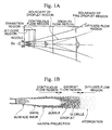
- Figures 1A and 1B are diagrams showing the structure of water jet discharged from a nozzle at a high pressure.
- Figure 2 is a graph showing the effect of water hammer caused by the droplets in the water jet.
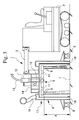
- Figure 3 is a side view showing the structure of the device for recovering the permeability of the first embodiment of the present invention.
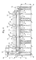
- Figure 4 is a front view showing the structure of the device for recovering the permeability of the first embodiment of the present invention.
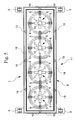
- Figure 5 is a bottom view showing the structure of the device for recovering the permeability of the first embodiment of the present invention.
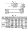
- Figure 6A is a diagram showing the process of the function recovery test for a car park by the present invention
- Figure 6B is a table showing results thereof.
- Figure 7 is a table showing the results of the water permeability recovery test for a wheel track, a non-wheel track, and a shoulder of a highway paved with a drainage material by the present invention.
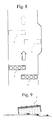
- Figure 8 is a diagram showing the process for a road by the device of the present invention.
- Figure 9 is a diagram showing the process for a road shoulder by the device of the present invention.
- Figures 10A and 10B are diagrams showing the device for recovering the permeability of the second embodiment of the present invention.
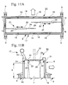
- Figures 11A and 11B are diagrams showing the device for recovering the permeability of the third embodiment of the present invention.
- the method for recovering the permeability of the pavement surface layer according to the present invention discharges water at a pressure (20 to 70 MPa as described below) which is sufficiently higher than that in the conventional high pressure cleaning process.
- the present invention discharges a water jet onto the surface of the pavement surface layer to remove clogging of the air voids and to recover the water permeability.
- water jet techniques are generally applied for surface preparation, demolishing, cutting or hole drilling of concrete material. When this conventional water jet technique is naturally applied to clean the road surface, the pavement surface layer may be damaged.
- the present invention basically differs from the known high pressure cleaning processes and the water jet processes, and removes the clogging while protecting the pavement surface layer based on the theory of fluid mechanics and impact engineering mentioned below.
- the water jet When a water jet is discharged at a high pressure into air, the water jet shows the structure as shown in Figure 1A (Katsuya Yanaida, and Akira Ohashi, "Research of Flow Characteristics of Water Jet in Air, Atomized Droplet Region, No. 2", Japan Mining Bulletin, 93-1073 (1977), 489).
- the water jet in the air is generally divided into three regions: a continuous flow region in which the water jet maintains continuity, a droplet flow region in which the water jet loses the continuity and becomes water droplets or globules, and a diffused flow region in which the water jet is atomized to produce mist.
- the water jet just after discharge from a nozzle has a smooth surface, and immediately produces surface waves.
- the amplitudes of the surface waves gradually become higher as the water jet flows downstream. Downstream of the surface waves, the surface unstably swirls, and then the fronts of the highly enlarged surface waves are doubled over, forming hairpin projections, while the air enters the water jet and the surface becomes disturbed by a number of air bubbles.
- the wave tips of the disturbed surface separate and become fine droplets and globules. This fragmentation gradually expands toward the center of the jet so that the water jet is fragmented into droplets and globules.
- the droplets and globules are further fragmented and finally are changed into a micro mist in the downstream diffused flow region.
- the droplets produced in the droplet flow region are approximately spherical because of their surface tension.
- the globules are more irregular in shape than the droplets, and the size of the globule is in a range of 10 to 100 ⁇ m.
- the present invention focuses on the droplets and globules produced in the droplet flow region in the water jet.
- the invention discharges the water jet onto the surface of the pavement surface layer so that the surface is within the droplet flow region and that a number of the fine droplets and globules enter the air voids and collide against the particles (contaminants). Then, water hammer efficiently removes the clogging of the air voids.
- the water hammer is actually caused by both, and hereinafter both droplets and globules are generally referred to as droplets.
- the water hammer power is not considerably high because the droplets are small, that is, 10 to 100 ⁇ m in diameter.
- the water hammer power by the droplet is obtained by the product of the water hammer pressure Pw and the cross sectional area of the droplet. If the droplet has a square cross section with 100 ⁇ m square, the water hammer power based on the above water hammer pressure Pw is merely 4.2 N (0.42kgf). This water hammer power does not cause any damage to the pavement surface layer.
- the diameters of the droplets are significantly smaller than those of the air voids so that the droplets surely enter the air voids.
- Figure 2 shows the results of an experiment for proving the water hammer effect by the droplets.
- Figure 2 shows the variation of a mass loss M of a sample metal, in this case, aluminum, depending on a distance X from the nozzle opening to the sample (Ryoji Kobayashi, "High Speed Water Jet Cutting of Solid Material (Research and Outlook)", Report Collection of Japan Society of Mechanical Engineers, Edition B, 52-483(1986), 3645).
- the inner diameter D 0 of the nozzle opening is 1 mm
- the discharge time is 60 seconds.
- "a” is a nozzle cross sectional area
- "g” is the gravity
- P is a discharge pressure measured upstream of the nozzle.
- the axis of ordinates indicates a dimensionless value obtained by dividing the mass loss M under the discharge pressure of 30 MPa, 50 MPa, 70 MPa, or 90 MPa by a momentum (2aP) of the jet stream.
- the axis of abscissas indicates a dimensionless standoff distance obtained by dividing the distance X by the nozzle opening diameter D 0 .
- the mass losses M have first peaks near the nozzle and second peaks distant from the nozzle.
- the first peaks are caused by the hydrowedge effect in the continuous flow region in the jet stream, and the second peaks are caused by the water hammer arising from the collision of the droplets.
- the range before and after the second peaks corresponds to the droplet flow region in the high pressure water jet. The water hammer which frequently occurs in this range is effective to remove the clogging in the pavement surface layer.
- the method for recovering the permeability of the pavement surface layer discharges the water jet from the nozzle at a high pressure onto the surface of the pavement surface layer so that the surface is within the droplet flow region.
- the dimensionless standoff distance indicated by the axis of abscissas in Figure 2 (the value obtained by dividing the standoff distance X by the nozzle diameter D 0 ) is set within the range around the second peaks, that is, 200 to 600.
- the standoff distance X is set to 20 to 60 cm.
- the discharge pressure P is below 20 MPa, the water hammer is reduced and the effect may be unsatisfactory.
- the discharge pressure P is preferably set to 20 to 70 MPa, and more preferably, to 30 to 70 MPa.
- the necessary amount of water is naturally determined based on the water pressure and the nozzle diameter, and approximately 40 to 200 lit/min. of water may be sufficient.
- the pressure of 20 to 70 MPa is considerably higher than those in the conventional high pressure cleaning processes (which in general employ approximately lower than 10 MPa), and is considerably lower than those in the conventional water jet processes (which in general employ more than 100 MPa).
- the conventional high pressure cleaning processes and water jet processes use the continuous flow region, in particular, a jet core just after the nozzle (as shown in Figure 1A) and do not include the idea of using the droplet flow region. Therefore, these conventional techniques normally set the standoff distance to several centimeters.
- the standoff distance of 20 to 60 cm in the embodiment (when the nozzle diameter is 1 mm) is considerably greater than those in the conventional techniques.
- the method for recovering the permeability of the pavement surface layer discharges the water jet at a high pressure onto the surface of the pavement surface layer by the above standoff distance, so that the fine droplets in the droplet flow region enter the air voids from the surface of the pavement surface layer at a high speed, and collide hard against the contaminant in the air voids. Then, the water hammer ejects the contaminants off to the surface, pushes the contaminants out of the spaces, or crushes the contaminant, thereby removing the clogging and recovering the permeability efficiently.
- Figures 3 to 5 show the first embodiment of the device for recovering the permeability of the pavement surface layer of the drainage road.
- a truck 1 which runs on a target road is coupled to a self-propelled car 2 by a connecting means 3, and is pulled or pushed by the car 2.
- a nozzle mechanism 5 for discharging the water jet.
- a nozzle 6 of the nozzle mechanism 5 discharges the water jet onto the surface of the pavement surface layer 7 so that the surface is within the droplet flow region.
- the truck 1 has a casing 8 which is open at the bottom.
- a vertically movable nozzle mechanism 5 is positioned in an upper area in the casing 8.
- Reference numerals 9 denote wheels attached to the underside of the casing 8.
- the nozzle mechanism 5 may be fixed to the casing 8 and the casing 8 may be moved in the vertical direction to adjust the standoff distance X.
- the casing 8 may be extensible.
- the embodiment has four nozzle mechanisms 5 aligned perpendicularly to the traveling direction of the truck 1.
- each nozzle mechanism 5 four rotors 11 are attached radially to the lower end of a rotation axis 10, forming a cross-shape.
- Two nozzles 6 are attached to the underside of the end of each rotor 11.
- a supply hose 13 for the water jet is connected via a swivel joint 12.
- the water jet is pumped by a high pressure pump, which is not shown, is supplied through the supply hose 13, the swivel joint 12, the rotation axis 10, and the rotors 11 to the nozzles 6, and is discharged from the nozzles 6 at a high pressure onto the surface of the pavement surface layer 7.
- All the nozzle mechanisms 5 are supported by a frame 14 attached to the upper side of the casing 8, and are rotated horizontally at the same speed by an oil hydraulic motor 15 and a power transmission mechanism 16.
- each nozzle mechanism 5 has the four rotors 11 and each rotor 11 has two nozzles 6, each nozzle mechanism 5 has in total eight nozzles 6. These eight nozzles 6 draw quadruple concentric circles, as shown in Figure 5 (as seen from the bottom side to the casing 8). As shown in Figure 4, the circles corresponding to the neighboring outermost nozzles 6 overlap.
- One of the nozzle pairs 6 attached to rotors 11 is a general orifice-type nozzle (circular jet nozzle), while the other is a fan-type nozzle (fan jet nozzle) for discharging the water jet over a wider area.
- the droplets from the fan-type nozzle are widely dispersed in the droplet flow region of the water jet so that the droplets effectively enter the air voids.
- the nozzle diameter D 0 of the orifice-type nozzle 6 is 1 mm
- the nozzle diameter D 0 of the fan-type nozzle 6 is 1.2 mm. Accordingly, the standoff distance X is appropriately set to a value obtained by multiplying the nozzle diameter D 0 by 200 to 600, that is, within 20 to 72 cm.
- the vacuum evacuator 17 comprises a slit 18 for vacuum evacuation formed between double walls of the casing 8 and along the edge of the casing 8.
- vacuum exhaust pipes 19 evacuate the casing 8 to prevent water from flowing around, and suck up dust and soil with the water to prevent clogging of the pavement surface layer.
- the number and positions of the vacuum exhaust pipes 19 are appropriately modified. The sucked water may be supplied through a filter and may be recycled.
- the standoff distance X is 20 to 72 cm obtained by multiplying the diameter by 200 to 600.
- the discharge pressure P is 20 to 70 MPa
- the amount of water is 40 to 200 l/min.
- the rotation speed of the nozzle mechanisms 5 is, for example, 300 rpm
- the traveling speed of the truck 1 is 4 m/min.
- the fine droplets in the droplet flow region of the water jet enter the air voids in the pavement surface layer, permeate deeply therethrough, intermittently collide against the contaminants, causing water hammer, which ejects the contaminants to the surface, pushes the contaminants out of the air voids, or crushes the contaminants, thereby removing the clogging and effectively recovering the water permeability.
- Figure 6 shows the result of the water permeability recovery test by the above device.
- the test was conducted at twelve points in four areas of a car park paved with a porous material 40 mm in thickness, and compares the water permeability before and after the process (the time in seconds required to drain 400 ml of water through the drainage material).
- the time was shortened to less than 5 seconds.
- this invention is considerably effective. Since, according to the standard of the water permeability of the drainage surface, 400 ml permeate within 10 seconds or 800 ml permeate within 15 seconds, the above results satisfy the standard.
- Figure 7 shows the results of the water permeability recovery test for a wheel track, a non-wheel track, and a shoulder of a highway paved with a drainage material.
- the water permeability is recovered at all points, and the times required to drain water are shortened to less than 7 seconds. Particularly, for seriously clogged road shoulders, considerable effects are achieved.
- the width of the truck 1 may correspond to a traffic lane, and the process for one lane may be finished by running on the lane once. This may increase the size of the device, and the device would be unable to handle a widened lane such as a bus stop or a turnout.
- two trucks 1 may run diagonally in front and behind and right and left as shown in Figure 8.
- the width of the trucks 1 may be 2 meters, and the running trucks 1 may be separated in the front-to-rear direction and may be overlapped with respect to the transverse direction. At a widening point of the road, one of the trucks 1 may slide to the transverse direction.
- the process is not effective. Therefore, after the first truck 1 discharges the water jet and the water is drained through the pavement surface layer 7, the second truck 1 discharges the water jet.
- the timing of the discharge of the water jet from the trucks 1 may be appropriately adjusted by changing the traveling speed of and the interval between the trucks 1.
- the dust and soil may be washed away to a side drain, or may be temporarily gathered and then removed.
- the truck 1 is slightly slanted to discharge the water jet obliquely as shown in Figure 9. The discharged water jet naturally forms a water flow on the surface of the pavement surface layer, washing away the dust and soil effectively.
- Figure 10 shows the second embodiment of the device for recovering the permeability according to the present invention.
- a truck 20 On a truck 20 is loaded a nozzle mechanism 21, in which a number of nozzles 23 are attached to an underside of a pipe 22, and the pipe 22 can be reciprocated in the transverse direction.
- the pipe 22 At the upper area within the casing 8, the pipe 22 is horizontally arranged along the traveling direction. Both ends of the pipe 22 are supported by guide rails 24 so that the pipe 22 can be reciprocated by a drive unit which is not shown.
- the pipe 22 is connected to a supply hose 25. While driving the truck 20 intermittently or continuously at a constant speed, the pipe 22 is reciprocated in the transverse direction, discharging the water jet from the nozzles 23 over the surface of the pavement surface layer 7.
- the standoff distance X is set to a value obtained by multiplying the nozzle diameter D 0 by 200 to 600 and the road surface is within the droplet flow region.
- the second embodiment achieves the same effect of recovering the function of the road surface layer as the first embodiment.
- the orifice-type nozzle and the fan-type nozzle may be used together.
- Figure 11 shows the third embodiment of the device for recovering the permeability according to the present invention.
- the third embodiment is based on the second embodiment and modifies the nozzle mechanism 21 to be aligned along the transverse direction with respect to the casing 8 (the direction perpendicular to the traveling direction).
- the casing 8 includes two pipes 22 which are separated in the front-to-rear direction and are supported by guide rails 24 so that the pipes 22 can be reciprocated between the middle and the sides of the casing 8. While driving the truck 20 constantly, the pipes 22 are reciprocated in the transverse direction, discharging the water jet from the nozzles 23 over the surface of the pavement surface layer 7.
- the device for recovering the permeability of the present invention may be modified and applied in various forms.
- four rotors 11 in the nozzle mechanism 5 form a cross-shape, two, three, five rotors 11, or more may be arranged in a radial pattern.
- the number of the nozzles 6 attached to the rotors 11 is not limited to two, and may be changed.
- the types of the nozzles 6 may optionally be changed.
- the number of the nozzle mechanisms 5 is not limited to four, and the nozzle mechanisms 5 form a line, more than two lines, or a zigzag line.
- the drive mechanism for rotating the nozzle mechanisms 5 is not limited to the oil hydraulic motor 15 and a power transmission mechanism 16, and may employ other structures, for example, electric motors for driving the nozzle mechanisms 5 independently.
- the second embodiment may include two or more pipes 22 which are synchronously or independently reciprocated.
- the third embodiment is not limited to the two pipes and may have one, three pipes, or more.
- the trucks 1 and 20 are pulled or pushed by the self-propelled car 2
- the trucks 1 and 20 may have drive units and may be self-propelled.
- the truck may be simply pushed by hand.
- the shape of the casing 8, the mechanism for adjusting the standoff distance X, and the presence or absence and the structure of the vacuum evacuator may be modified.
- the water jet is discharged from a nozzle onto a surface of the object so that the surface of the object is within a droplet flow region of the water jet and that the droplets and globules cause water hammer.
- the discharge pressure at the nozzle is within 20 to 70 MPa
- the dimensionless standoff distance obtained by dividing a real standoff distance between the nozzle and the object surface by a diameter of the nozzle is within 200 to 600.
- the water jet may be discharged obliquely to cause a water flow in one direction on the surface of the object.
Landscapes
- Engineering & Computer Science (AREA)
- Architecture (AREA)
- Civil Engineering (AREA)
- Structural Engineering (AREA)
- Road Repair (AREA)
- Road Paving Structures (AREA)
Applications Claiming Priority (4)
| Application Number | Priority Date | Filing Date | Title |
|---|---|---|---|
| JP582599 | 1999-01-12 | ||
| JP582599 | 1999-01-12 | ||
| JP14080399 | 1999-05-20 | ||
| JP14080399A JP3295389B2 (ja) | 1999-01-12 | 1999-05-20 | 通水機能を有する舗装表層材の機能回復方法および装置 |
Publications (2)
| Publication Number | Publication Date |
|---|---|
| EP1020566A2 true EP1020566A2 (fr) | 2000-07-19 |
| EP1020566A3 EP1020566A3 (fr) | 2001-08-22 |
Family
ID=26339837
Family Applications (1)
| Application Number | Title | Priority Date | Filing Date |
|---|---|---|---|
| EP99308109A Withdrawn EP1020566A3 (fr) | 1999-01-12 | 1999-10-14 | Procédé et dispositif de récupération de la perméabilité d'un revêtement drainant |
Country Status (3)
| Country | Link |
|---|---|
| US (1) | US20020121559A1 (fr) |
| EP (1) | EP1020566A3 (fr) |
| JP (1) | JP3295389B2 (fr) |
Cited By (7)
| Publication number | Priority date | Publication date | Assignee | Title |
|---|---|---|---|---|
| WO2002097197A1 (fr) * | 2001-05-31 | 2002-12-05 | Tennant Company | Tete de nettoyeuse sans brosse pour entretien de surface |
| EP2354315A1 (fr) * | 2010-02-08 | 2011-08-10 | Skanska Sverige AB | Système de nettoyage et d'élimination de matériau, utilisation dudit système et procédé pour le nettoyage et d'élimination de matériau d'une route asphaltée |
| EP2906755A4 (fr) * | 2012-10-10 | 2016-06-15 | Sinvent As | Dispositif et procédé de dispersion de pétrole sur l'eau |
| CN110396965A (zh) * | 2019-07-09 | 2019-11-01 | 刘炳周 | 一种用于园林的树叶收集装置 |
| US10683626B2 (en) | 2012-10-10 | 2020-06-16 | Sinvent As | Device and method for dispersing oil on water |
| EP3772552A3 (fr) * | 2019-08-08 | 2021-06-30 | Albert Leitner | Sol composite poreux et dispositif de nettoyage |
| DE102020120130A1 (de) | 2020-07-30 | 2022-02-03 | Wehner Metalltechnik GmbH & Co. KG | Reinigungsvorrichtung und Reinigungsfahrzeug |
Families Citing this family (9)
| Publication number | Priority date | Publication date | Assignee | Title |
|---|---|---|---|---|
| US20040231709A1 (en) * | 2001-12-13 | 2004-11-25 | Shin Narui | Method of inspecting concrete surface and method of repairing same |
| JP4510502B2 (ja) * | 2004-04-19 | 2010-07-28 | 株式会社佐藤渡辺 | コンクリートハツリ機 |
| JP5666501B2 (ja) * | 2012-03-14 | 2015-02-12 | 株式会社キクテック | 除染処理方法とその方法に使用可能な表面処理装置 |
| US20140041691A1 (en) * | 2012-08-09 | 2014-02-13 | Wade Glasscock | Mobile washing apparatus |
| JP5957370B2 (ja) * | 2012-11-08 | 2016-07-27 | 鹿島建設株式会社 | 道路洗浄装置及び道路舗装の洗浄方法 |
| JP5687678B2 (ja) * | 2012-11-12 | 2015-03-18 | 昌彦 辻田 | 放射性物質の洗浄装置 |
| KR102291227B1 (ko) * | 2019-01-29 | 2021-08-20 | 김수곤 | 수저 표층 퇴적물 친환경 준설장치 |
| KR102237084B1 (ko) * | 2019-01-29 | 2021-04-07 | (주)신대양 | 밀폐성이 향상된 수저 표층 퇴적물 친환경 준설장치 |
| CN113445458B (zh) * | 2021-07-30 | 2024-09-20 | 国投物业有限责任公司北京三分公司 | 一种透水混凝土的清洁装置及基于此装置的清洁方法 |
Family Cites Families (8)
| Publication number | Priority date | Publication date | Assignee | Title |
|---|---|---|---|---|
| US3548543A (en) * | 1961-06-07 | 1970-12-22 | Ajem Lab Inc | Devices for power washing,surface reforming and the like |
| US3146550A (en) * | 1961-07-07 | 1964-09-01 | Ajem Lab Inc | Abrasive blasting machine |
| GB8329786D0 (en) * | 1983-11-08 | 1983-12-14 | Aqua Dyne Europ Ltd | Treating road surfaces &c |
| FR2702397B1 (fr) * | 1993-03-11 | 1995-04-14 | Uwer Assainissement Ets J | Dispositif de projection d'un fluide sous pression et machine de nettoyage de surfaces, notamment de chaussées. |
| FR2704781B1 (fr) * | 1993-05-05 | 1995-07-28 | Colas Sa | Dispositif de nettoyage, appareil et vehicule de nettoyage pour surface rugueuses. |
| CH692155A5 (de) * | 1996-08-21 | 2002-02-28 | Hurgli Juerg | Strassenreinigungsmaschine. |
| US6029746A (en) * | 1997-07-22 | 2000-02-29 | Vortech, Inc. | Self-excited jet stimulation tool for cleaning and stimulating wells |
| US20040231709A1 (en) * | 2001-12-13 | 2004-11-25 | Shin Narui | Method of inspecting concrete surface and method of repairing same |
-
1999
- 1999-05-20 JP JP14080399A patent/JP3295389B2/ja not_active Expired - Fee Related
- 1999-10-14 EP EP99308109A patent/EP1020566A3/fr not_active Withdrawn
-
2002
- 2002-04-30 US US10/135,304 patent/US20020121559A1/en not_active Abandoned
Non-Patent Citations (1)
| Title |
|---|
| RYOJI KOBAYASHI: "High speed water jet cutting of solid material (research and outlook)", JAPAN SOCIETY OF MECHANICAL ENGINEERS. EDITION B 52-483(1986), 3645, 1986 |
Cited By (9)
| Publication number | Priority date | Publication date | Assignee | Title |
|---|---|---|---|---|
| WO2002097197A1 (fr) * | 2001-05-31 | 2002-12-05 | Tennant Company | Tete de nettoyeuse sans brosse pour entretien de surface |
| US6896742B2 (en) | 2001-05-31 | 2005-05-24 | Tennant Company | Brushless scrub head for surface maintenance |
| EP2354315A1 (fr) * | 2010-02-08 | 2011-08-10 | Skanska Sverige AB | Système de nettoyage et d'élimination de matériau, utilisation dudit système et procédé pour le nettoyage et d'élimination de matériau d'une route asphaltée |
| EP2906755A4 (fr) * | 2012-10-10 | 2016-06-15 | Sinvent As | Dispositif et procédé de dispersion de pétrole sur l'eau |
| US10683626B2 (en) | 2012-10-10 | 2020-06-16 | Sinvent As | Device and method for dispersing oil on water |
| CN110396965A (zh) * | 2019-07-09 | 2019-11-01 | 刘炳周 | 一种用于园林的树叶收集装置 |
| EP3772552A3 (fr) * | 2019-08-08 | 2021-06-30 | Albert Leitner | Sol composite poreux et dispositif de nettoyage |
| EP4502275A2 (fr) | 2019-08-08 | 2025-02-05 | Albert Leitner | Revêtement de sol composite |
| DE102020120130A1 (de) | 2020-07-30 | 2022-02-03 | Wehner Metalltechnik GmbH & Co. KG | Reinigungsvorrichtung und Reinigungsfahrzeug |
Also Published As
| Publication number | Publication date |
|---|---|
| EP1020566A3 (fr) | 2001-08-22 |
| JP2000265434A (ja) | 2000-09-26 |
| US20020121559A1 (en) | 2002-09-05 |
| JP3295389B2 (ja) | 2002-06-24 |
Similar Documents
| Publication | Publication Date | Title |
|---|---|---|
| US20020121559A1 (en) | Method and device for recovering permeability of porous pavement surface layer | |
| CA2424130C (fr) | Appareil de lavage de pneus et de roues de vehicules | |
| KR100926900B1 (ko) | 사계절 운영이 가능한 도로 분진 청소차 | |
| FI88320B (fi) | Snoeroejningsflaekt - foerfarande och apparatur foer att avlaegsna snoe fraon vaegar | |
| EP2354315B1 (fr) | Système de nettoyage et d'élimination de matériau, utilisation dudit système et procédé pour le nettoyage et d'élimination de matériau d'une route asphaltée | |
| CN106930220A (zh) | 多级水击路面凹陷空腔余动力导流板快速收集除尘装置 | |
| JP3000100B2 (ja) | 空隙を有する舗装の透水機能回復方法及び装置 | |
| JP5780677B2 (ja) | トンネル清掃装置及び方法 | |
| JP2003129415A (ja) | 舗装表面の処理装置 | |
| JPH11269835A (ja) | 水力式砂塵等回収装置、及び水力式砂塵等掃出し装置、並びにこれらを備えた水力式路面清掃車 | |
| KR100500021B1 (ko) | 흡입장치가 구비된 살수차 | |
| JP2000212925A (ja) | 舗装面の清掃・排水機能回復方法および装置 | |
| KR20140124290A (ko) | 이물질 제거장치 | |
| JPH08165622A (ja) | 舗装の目詰まり物の除去方法及び装置 | |
| KR200359857Y1 (ko) | 흡입장치가 구비된 살수차 | |
| JP4243891B2 (ja) | 舗装の目詰まり物の除去装置 | |
| JP2003184041A (ja) | 舗装の目詰まり物の除去装置、舗装の排水機能回復車、舗装の目詰まり物の除去方法および除去システム | |
| JP2004237913A (ja) | タイヤ洗浄装置 | |
| KR200362072Y1 (ko) | 노면 가공장치 | |
| JP2001159110A (ja) | 透水性舗装の路面洗浄方法及び洗浄装置 | |
| JP2005048421A (ja) | 路面清掃装置、路面清掃車両、および路面清掃方法 | |
| JP2006037356A (ja) | 通水機能回復方法及び装置 | |
| JPH0959949A (ja) | 舗装の目詰まり物の除去装置 | |
| JP2003342924A (ja) | 舗装の目詰まり物の吸引装置、舗装の目詰まり物の除去装置および排水性舗装の機能維持車 | |
| JPH1088540A (ja) | 空隙を有する舗装の掃除方法及び掃除車両 |
Legal Events
| Date | Code | Title | Description |
|---|---|---|---|
| PUAI | Public reference made under article 153(3) epc to a published international application that has entered the european phase |
Free format text: ORIGINAL CODE: 0009012 |
|
| AK | Designated contracting states |
Kind code of ref document: A2 Designated state(s): AT BE CH CY DE DK ES FI FR GB GR IE IT LI LU MC NL PT SE |
|
| AX | Request for extension of the european patent |
Free format text: AL;LT;LV;MK;RO;SI |
|
| PUAL | Search report despatched |
Free format text: ORIGINAL CODE: 0009013 |
|
| AK | Designated contracting states |
Kind code of ref document: A3 Designated state(s): AT BE CH CY DE DK ES FI FR GB GR IE IT LI LU MC NL PT SE |
|
| AX | Request for extension of the european patent |
Free format text: AL;LT;LV;MK;RO;SI |
|
| 17P | Request for examination filed |
Effective date: 20020208 |
|
| AKX | Designation fees paid |
Free format text: AT BE CH CY DE DK ES FI FR GB GR IE IT LI LU MC NL PT SE |
|
| RAP1 | Party data changed (applicant data changed or rights of an application transferred) |
Owner name: KYOEI CO., LTD. |
|
| RAP1 | Party data changed (applicant data changed or rights of an application transferred) |
Owner name: ANDERSON TECHNOLOGY CORPORATION |
|
| 17Q | First examination report despatched |
Effective date: 20040205 |
|
| STAA | Information on the status of an ep patent application or granted ep patent |
Free format text: STATUS: THE APPLICATION IS DEEMED TO BE WITHDRAWN |
|
| 18D | Application deemed to be withdrawn |
Effective date: 20080402 |