EP4502275A2 - Revêtement de sol composite - Google Patents
Revêtement de sol composite Download PDFInfo
- Publication number
- EP4502275A2 EP4502275A2 EP24215227.0A EP24215227A EP4502275A2 EP 4502275 A2 EP4502275 A2 EP 4502275A2 EP 24215227 A EP24215227 A EP 24215227A EP 4502275 A2 EP4502275 A2 EP 4502275A2
- Authority
- EP
- European Patent Office
- Prior art keywords
- floor covering
- composite floor
- fleece
- road shoulder
- sections
- Prior art date
- Legal status (The legal status is an assumption and is not a legal conclusion. Google has not performed a legal analysis and makes no representation as to the accuracy of the status listed.)
- Pending
Links
Images


Classifications
-
- E—FIXED CONSTRUCTIONS
- E01—CONSTRUCTION OF ROADS, RAILWAYS, OR BRIDGES
- E01C—CONSTRUCTION OF, OR SURFACES FOR, ROADS, SPORTS GROUNDS, OR THE LIKE; MACHINES OR AUXILIARY TOOLS FOR CONSTRUCTION OR REPAIR
- E01C11/00—Details of pavings
- E01C11/22—Gutters; Kerbs ; Surface drainage of streets, roads or like traffic areas
- E01C11/224—Surface drainage of streets
- E01C11/225—Paving specially adapted for through-the-surfacing drainage, e.g. perforated, porous; Preformed paving elements comprising, or adapted to form, passageways for carrying off drainage
- E01C11/226—Coherent pavings
-
- E—FIXED CONSTRUCTIONS
- E01—CONSTRUCTION OF ROADS, RAILWAYS, OR BRIDGES
- E01C—CONSTRUCTION OF, OR SURFACES FOR, ROADS, SPORTS GROUNDS, OR THE LIKE; MACHINES OR AUXILIARY TOOLS FOR CONSTRUCTION OR REPAIR
- E01C11/00—Details of pavings
- E01C11/16—Reinforcements
- E01C11/165—Reinforcements particularly for bituminous or rubber- or plastic-bound pavings
-
- E—FIXED CONSTRUCTIONS
- E01—CONSTRUCTION OF ROADS, RAILWAYS, OR BRIDGES
- E01C—CONSTRUCTION OF, OR SURFACES FOR, ROADS, SPORTS GROUNDS, OR THE LIKE; MACHINES OR AUXILIARY TOOLS FOR CONSTRUCTION OR REPAIR
- E01C11/00—Details of pavings
- E01C11/22—Gutters; Kerbs ; Surface drainage of streets, roads or like traffic areas
- E01C11/224—Surface drainage of streets
- E01C11/225—Paving specially adapted for through-the-surfacing drainage, e.g. perforated, porous; Preformed paving elements comprising, or adapted to form, passageways for carrying off drainage
-
- E—FIXED CONSTRUCTIONS
- E01—CONSTRUCTION OF ROADS, RAILWAYS, OR BRIDGES
- E01C—CONSTRUCTION OF, OR SURFACES FOR, ROADS, SPORTS GROUNDS, OR THE LIKE; MACHINES OR AUXILIARY TOOLS FOR CONSTRUCTION OR REPAIR
- E01C3/00—Foundations for pavings
- E01C3/006—Foundations for pavings made of prefabricated single units
-
- E—FIXED CONSTRUCTIONS
- E01—CONSTRUCTION OF ROADS, RAILWAYS, OR BRIDGES
- E01C—CONSTRUCTION OF, OR SURFACES FOR, ROADS, SPORTS GROUNDS, OR THE LIKE; MACHINES OR AUXILIARY TOOLS FOR CONSTRUCTION OR REPAIR
- E01C3/00—Foundations for pavings
- E01C3/06—Methods or arrangements for protecting foundations from destructive influences of moisture, frost or vibration
-
- E—FIXED CONSTRUCTIONS
- E01—CONSTRUCTION OF ROADS, RAILWAYS, OR BRIDGES
- E01C—CONSTRUCTION OF, OR SURFACES FOR, ROADS, SPORTS GROUNDS, OR THE LIKE; MACHINES OR AUXILIARY TOOLS FOR CONSTRUCTION OR REPAIR
- E01C7/00—Coherent pavings made in situ
- E01C7/08—Coherent pavings made in situ made of road-metal and binders
- E01C7/30—Coherent pavings made in situ made of road-metal and binders of road-metal and other binders, e.g. synthetic material, i.e. resin
-
- E—FIXED CONSTRUCTIONS
- E01—CONSTRUCTION OF ROADS, RAILWAYS, OR BRIDGES
- E01C—CONSTRUCTION OF, OR SURFACES FOR, ROADS, SPORTS GROUNDS, OR THE LIKE; MACHINES OR AUXILIARY TOOLS FOR CONSTRUCTION OR REPAIR
- E01C7/00—Coherent pavings made in situ
- E01C7/08—Coherent pavings made in situ made of road-metal and binders
- E01C7/32—Coherent pavings made in situ made of road-metal and binders of courses of different kind made in situ
-
- E—FIXED CONSTRUCTIONS
- E01—CONSTRUCTION OF ROADS, RAILWAYS, OR BRIDGES
- E01C—CONSTRUCTION OF, OR SURFACES FOR, ROADS, SPORTS GROUNDS, OR THE LIKE; MACHINES OR AUXILIARY TOOLS FOR CONSTRUCTION OR REPAIR
- E01C7/00—Coherent pavings made in situ
- E01C7/08—Coherent pavings made in situ made of road-metal and binders
- E01C7/32—Coherent pavings made in situ made of road-metal and binders of courses of different kind made in situ
- E01C7/325—Joining different layers, e.g. by adhesive layers; Intermediate layers, e.g. for the escape of water vapour, for spreading stresses
Definitions
- the invention relates to a composite floor covering according to the preamble of claim 1 and to a road shoulder or a road surface which is designed as such a composite floor covering.
- Composite floor coverings for open spaces with a mineral granulate bound with a polymer material are known from the state of the art.
- polymer granulate can also be provided in a bound or unbound form.
- a water-permeable stone composite molded body which consists of 99 to 65 percent by weight of granules made of mineral plastics with a grain size of 0.5 to 100 mm and 1 to 35 percent by weight of a two-component polyurethane adhesive.
- a masonry can be provided for building gabion stone basket walls, whereby the stones are vibrated within the gabion stone basket or are firmly connected to one another with filling material or by means of binding materials.
- a roadside verge is also known, whereby the basic body of the verge consists of a mixture of stone, sand, humus and numerous other elements, which is covered by a layer of geotextile. This ensures such a stable Vegetation layer is designed so that it can also be used on roadside verges or as parking spaces without vehicles sinking into the grass.
- the DE 41 30 768 C1 discloses a bearing and support cushion for earth and road construction.
- the core material is covered by a geotextile or random fiber fleece, and it is also proposed to provide geotextile layers within the support cushions that run over parts of the cross-section.
- the EP 1 464 756 A1 A structure for a playground can be seen, whereby the layer structure is reinforced by geotextile layers.
- composite floor coverings made of mineral granules and polymer material have been criticized for their environmental impact because of the polymaterial. Even with bound polymaterial, abrasion is unavoidable, meaning that microplastics end up in the environment.
- a filter system for filtering ions, complexes or other particles from an aqueous flow.
- the filter device can be made of different materials, such as sand, polymer material, ash, perlite or a solid, porous matrix, such as CPP (Cementious porous pavement).
- the CPP is preferably porous enough so that water can flow through the pores.
- a road shoulder can be provided with such a CPP, for example.
- Membrane filters with a pore size in the order of 0.1 to 50 microns and even up to 3000 or more microns are disclosed as another filter material. This membrane material is preferably made of cellulose.
- the GB 2 416 130 A shows a structure for a floor covering in which different grain materials are used.
- a fleece can be used, among other things.
- the GB 2 396 379 A refers to a floor covering for draining water, which is made up of different layers.
- a surface layer can be porous asphalt or porous concrete.
- the porous asphalt can contain bitumen, whereby the bitumen can be interspersed with a polymer, and granular aggregates. Under the surface layer there are further coarser layers and a semi-permeable membrane.
- the membrane is a synthetic woven geotextile membrane.
- a laminated geotextile is made up of a number of layers and is intended for use as a filter and/or drainage layer.
- the layers include woven or non-woven geotextiles made of different materials with different strengths and pore sizes.
- the CN 106 565 175 A discloses a floor covering made up of several layers for draining or storing water, whereby the layers are characterized by different material compositions.
- the materials range from concrete to quartz sand to polyurethane.
- a water-permeable geotextile is provided between a base layer and the layer above.
- EP 1020566 A2 describes a device and a method for restoring the water permeability of a porous paving surface layer of a drainage system or a water-permeable paving.
- a high-pressure water jet is ejected onto the surface to clean clogged air pores.
- the EP 2210982 A2 has a mobile high-pressure cleaning machine for outdoor plastic floors.
- the high-pressure cleaning machine has a spray device for spraying water under high pressure against a floor surface to be cleaned and a collection device for collecting sprayed water and dirt using suction air.
- the task is therefore to create a composite floor covering that is very environmentally friendly and can provide a filtering effect in the long term.
- the porous composite floor covering or polymer covering is provided which is provided with at least one filter fleece section and which consists of a mineral granulate which is bonded to the polymer material to form a porous composite floor covering.
- the composite floor covering is characterized in that several filter fleece sections are arranged in the composite floor covering, wherein the filter fleece sections are arranged in at least two levels are arranged offset from one another and overlap in the vertical projection and wherein the filter fleece sections have a pore size of not more than 100 ⁇ m.
- a fleece is preferably arranged at least on the underside of the covering, whereby the fleece can be provided with a pore opening of no more than 100 ⁇ m.
- the porous composite floor covering has a first filtering effect for coarse-grained materials, such as sand. This is retained in the pores of the composite floor covering. Fine dust, including microplastics, is washed by water through the composite floor covering to the fleece and held there, thus preventing it from entering the environment.
- the fleece thus serves as a second filter to capture fine dust and other fine particles.
- the composite floor covering can be cleaned at regular intervals.
- a high-pressure water jet is pressed into the composite floor covering and the water is sucked out again using a suction device.
- a composite floor covering made of mineral particles bonded to a polymer material can, on the one hand, have the necessary coarse porosity required to filter coarse particles and which allows water to be pressed in, and, on the other hand, is so stable that such a cleaning process can be carried out repeatedly with water under high pressure.
- porous floor coverings in which the particles are bonded to a mineral binding agent, for example cement-based. Large pores can also be provided here.
- mineral binding agents are not elastic, which means that they break and are destroyed when cleaned with water under high pressure. With such floor coverings, the particles would come off during repeated cleaning.
- a porous composite floor covering which is made of a mineral granulate and an elastic polymer material, and a fleece with a small pore size allows the filtering of coarse and fine substances and can be cleaned regularly, so that a long-term filtering effect is possible.
- the fleece has a pore size of no more than 100 ⁇ m. It can also be made even finer and preferably no more than 50 ⁇ m in order to reliably retain the microparticles and fine dust.
- the coating can be removed after its service life and disposed of properly.
- the surface can be used for road shoulders.
- the composite floor covering according to the invention can be used to produce water-permeable, open-pored bound road shoulders as well as car parking areas and retention systems for surface drainage (troughs, ditches, infiltration basins) of the roadways and parking areas.
- the composite floor covering can also be used as a sports floor covering, in particular tennis court or football field covering, where a fine-grained granulate can be loosely applied to this to correspond to a conventional sand court.
- This granulate can be a plastic granulate or sand granulate. This can lead to plastic abrasion, which is caught by the fleece. The coarse-grained plastic granulate is rubbed off during use, so that fine-grained abrasion occurs. The sand granulate causes fine-grained abrasion on the composite floor covering.
- a cleaning device not according to the invention can be provided for cleaning a composite floor covering as explained above, wherein the cleaning device has a cleaning nozzle for forcing water or an aqueous solution into the porous floor covering and a suction device for sucking the water out of the floor covering.
- the cleaning device preferably has a filter device for filtering the extracted water. This allows the water to be reused and a concentrate of dirt to be collected. This is particularly useful when the cleaning device is arranged on a street cleaning vehicle.
- the cleaning device can have a suction or pressure bar in which one or more cleaning nozzles and/or one or more suction nozzles are integrated.
- the suction or pressure bar has a length of at least 30 cm and preferably at least 50 cm.
- the maximum length of the suction or pressure bar is preferably 1 m or 1.2 m.
- a street cleaning vehicle for cleaning the composite floor covering as explained above can be provided, wherein the street cleaning vehicle has a cleaning device as explained above.
- Such a street cleaning vehicle with a suction or pressure bar is preferably designed in such a way that the suction or pressure bar can be arranged at different angles of inclination with respect to the direction of travel of the street cleaning vehicle. This allows the effective width to be changed by tilting the suction or pressure bar and to be adapted to the width of the section to be cleaned, in particular the road shoulder to be cleaned.
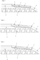
- a first embodiment of a composite floor covering 1 is explained below, which forms a banquet ( Figure 1 ).
- the composite floor covering 1 is made of a mineral granulate and a binding agent.
- the mineral granulate includes, for example, gravel and/or splinters (soft and hard rocks such as limestone, diabase, basalt, gneiss).
- the mineral granulate can consist of a grain mixture of 2/5 mm (i.e. a grading curve between 2 mm and 5 mm), 4/8 mm or 8/16 mm, with a proportion of fine-grained material up to 0.2 mm preferably amounting to a maximum of 10% of the mass weight of the rock in the covering.
- the grading curve is determined individually depending on the load and requirements of the respective trade.
- the binding agent can be made from a 1-component or 2-component coating material, for example based on polyurethane.
- a 1-component or 2-component coating material for example based on polyurethane.
- other polymers such as those based on epoxy, polyethylene, polypropylene, etc., are also suitable as binding agents.
- a composite floor covering made from these polymers is resistant to frost and de-icing salt.
- the binding agent is between 3% and 5% by mass.
- the binding agent's mass proportion should not be greater than 10% in order to ensure sufficient porosity of the composite covering.
- the greater the binding agent's mass proportion the lower the porosity of the composite covering 1 is as a rule. If the binding agent's mass proportion is very low, this can impair the strength of the composite covering. It is therefore advisable to provide a binding agent's mass proportion of the composite covering of at least 1% and in particular at least 2%.
- the composite floor covering 1 can be designed with a void content of at least 20% by volume, preferably at least 25% by volume and in particular at least 30% by volume.
- the preferred embodiment has a void content of 32% by volume.
- the pore size for a grain mixture of 4/8 mm is a maximum of 10 mm.
- the minimum pore size is generally in the range of 0.5 to 3 mm. This means that there is a high water permeability and a good filtering effect for coarse particles.
- a filter fleece 2 is provided as a filter medium for fine particles.
- the filter fleece is preferably designed with a minimum weight of 250 g/m 2.
- the weight of the filter fleece can also be significantly higher.
- the filter fleece has a maximum porosity of 100 ⁇ m.
- the porosity can also be smaller and limited, for example, to a maximum of 75 ⁇ m or 50 ⁇ m or 25 ⁇ m or 20 ⁇ m.
- Such filter fleeces are available from Noravin.
- the porosity of the composite material is one or more orders of magnitude greater than that of the filter fleece. This ensures that water flows through the composite material in sufficient quantities and is filtered by the filter fleece.
- the pore size of the filter fleece is preferably larger than 10 ⁇ m. This ensures sufficient water permeability.
- the filter fleece is laid under the composite covering 1, which forms a shoulder, and is pulled up on the flanks to the shoulder surface.
- the composite floor covering 1 has, in addition to the filter fleece 2, also internal filter fleece sections 3.
- These internal filter fleece sections 3 can be designed with different porosities than the filter fleece 2 and thus serve for coarse and fine filtration.
- the composite floor covering 1 rests on an unbound base layer 5. At the edge area, it rests with an edge section on a bound base layer 6 (asphalt ...), which is arranged horizontally abutting the composite floor covering, with the surfaces being flush or forming a continuous transition.
- a bound base layer 6 (asphalt 7)
- a topsoil 4 e.g. humus
- the base layer 6 has an approximately horizontal surface.
- the surface of the composite floor covering 2 is inclined from the base layer towards the topsoil 4. The incline is, for example, approximately 5° to 10° compared to the base layer 6.
- the topsoil can have the same incline, be even more inclined, or be less steep and even horizontal.
- the width of the composite floor covering is based on the RVS specifications for banquets.
- the filter fleece 2 is arranged at least on the entire underside of the composite floor covering and is pulled up and installed like a trough at the joint areas to the supporting layer 6 and the topsoil 4.
- the filter fleece 2 thus forms a channel-shaped trough.
- the inner filter fleece sections 3 are designed as strip-shaped sections which extend in the longitudinal direction of the composite floor covering. They are arranged, for example, parallel to the underside of the composite floor covering.
- the composite floor covering 2 has a minimum thickness of 8 cm according to RVS. However, for other applications of the composite floor covering, the minimum thickness can also be lower.
- the specific design of a verge depends on the requirements of the respective JDTV classes, which are determined according to the respective traffic volume (vehicles in 24 hours).
- the design of the composite floor covering can vary accordingly.
- the road shoulder is designed with an incline of approximately 5° to 10° relative to the roadway and has a
- FIG. 1 to 4 differ mainly in the arrangement of the inner filter fleece sections 3.
- FIG. 1 to 4 several strip-shaped filter fleece sections 3 are provided, which are arranged alternately offset from one another in several levels (here two levels; in principle more levels are also possible).
- the individual filter fleece sections 3 are arranged to overlap one another slightly. This achieves a flat covering without the strength of the composite floor covering 1 being impaired too much.
- the width and number of filter fleece sections 3 can vary.
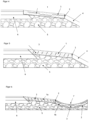
- a fifth embodiment not according to the invention has several filter fleece sections 3, which are arranged at an angle to the underside or the top of the composite floor covering 1.
- the inclination of the filter fleece sections 3 is such that they are inclined in the opposite direction to the composite floor covering 1, whereby the inclination is steeper, whereby they oppose water running off within the composite floor covering 1 due to the inclination of the same and thus bring about a certain retention function, which increases the filter effect ( Figure 5 ).
- a first and a second section of a composite floor covering 1a, 1b are provided.
- the first composite floor section 1a forms a banquet which essentially corresponds to the embodiments explained above.
- This composite floor section 1a has several filter fleece sections 3 which are arranged obliquely opposite the underside or the top of the composite floor covering 1.
- the inclination of the filter fleece sections 3 is such that they are inclined in the same direction as the composite floor covering 1, whereby the inclination is steeper, whereby they direct the water to the underside of the composite floor covering 1a.
- the composite floor section 1a can also be designed without filter fleece sections 3 or with the arrangements of the filter fleece sections 3 shown above.
- the second composite floor section 1b On the side facing away from the bound base layer, the second composite floor section 1b is arranged in abutment with the first composite floor section 1a.
- the second composite floor section 1b forms a drainage trough 7.
- a filter fleece 2 is arranged below each of the two composite floor sections, which are pulled up laterally in a trough-like manner on the front sides of the composite floor sections 1a, 1b.
- Internal filter fleece sections 3 are also arranged in the second composite floor section 1b, which are strip-shaped and arranged parallel to the underside of the composite floor section 1b. These internal filter fleece sections 3 can be modified in the same way as those of the embodiments explained above.
- FIG. 7 a schematic cross-sectional view of a seepage basin 16 is shown, which is provided with the composite floor covering 1 according to the invention and has a humus-sand mixture 8 on it.
- a water-permeable gravel layer 15 is arranged under the covering.
- the composite floor covering 1 serves as a permanent filter.
- the composite floor covering 1 has internal filter fleece sections 3, which are arranged offset from one another in two levels.
- the different levels of internal filter fleece sections 3 have an increasingly lower porosity towards the bottom, so that the upper levels initially filter out the coarse material and the lower levels filter the increasingly finer material.
- FIG 8 is a schematic cross-sectional view of the composite floor covering 1 according to the invention when used in a football field, with a dynamic layer 10 placed on the composite floor covering 1 and a football field artificial turf placed on top of that. Underneath the covering, just as in the previously described embodiments, there is an unbound base layer 5 and sections with gravel 11 (grading curve preferably 16/32 mm) in which drainage pipes 12 are arranged.
- the dynamic layer can also be arranged below the composite floor covering 1 or can be omitted completely.
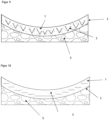
- FIGs 9 and 10 There are two variants of the formed drainage trough 7 according to the embodiment of the Figure 6 which differ in the different arrangements of the inner filter fleece 2 for coarse and fine filtration (see the Figures 2 to 5 ).
- the inner filter fleece sections 3 form approximately V-shaped channels in cross section, preferably extending in the longitudinal direction, which filter water very efficiently.
- the Figure 10 the strip-shaped, inner filter fleece sections 3 are aligned horizontally.
- FIG 11 is a schematic cross-sectional view of the composite floor covering according to the invention when used in a tennis court, with a base layer 14 and a dynamic layer 10 and the tennis court top layer being placed on top of the covering.
- a base layer 14 and a dynamic layer 10 and the tennis court top layer being placed on top of the covering.
- Under the covering just as in the case of the Figure 8 shown embodiment sections with gravel 11, in each of which a drainage pipe 12 is arranged.
- the composite floor covering 1 can also form the top layer of a tennis court, whereby quartz sand and/or plastic granulate can be loosely applied to the top layer.
- the substructure can be designed with or without drainage pipes.
- an elastic, dynamic layer is preferably arranged beneath the composite floor covering 1, which elastically absorbs shocks.
- All of the above-explained embodiments have in common that they have at least one filter fleece 2, which is preferably arranged on the underside of the composite floor covering 1 and in particular over the entire surface of the composite floor covering.
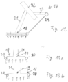
- the composite floor covering 1 can be regularly cleaned with a cleaning device 17 in order to remove dirt from the pores of the composite floor covering 1 and/or the filter fleece 2.
- the cleaning device 17 has a suction or pressure bar 18, which has a suction nozzle 19 and one or more cleaning nozzles 20.
- the suction nozzle 19 is connected to a suction pipe 21, which also serves as a holding device for the suction or pressure bar 18.
- the suction pipe 21 leads into a filter device 22, in which sucked-in water is separated from the dirt.
- a further suction pipe 23 leads away from the filter device 22, which can be connected to a corresponding suction device.
- the suction device (not shown) is preferably integrated into a street cleaning vehicle.
- a water line 24 is also provided, which leads to the cleaning nozzles 20, from which the water emerges downwards under high pressure.
- the water line 24 is connected to a water pump (not shown), with which water can be supplied under pressure. In practice, it has been shown that a pressure of over 100 bar is very advantageous.
- the cleaning nozzles 20 can be outside the suction nozzle 19 ( Figure 13a ) or inside the suction nozzle 19, as shown in Figure 13b is shown.
- the Figure 13a and Figure 13b are each a cross-sectional view transverse to the direction of movement of the cleaning device.
- Figure 12 shows the cleaning device 17 from the front.
- the suction or pressure bar 18 is positioned a few centimeters above the composite floor covering 1 during cleaning. Water or an aqueous solution is introduced into the composite floor covering 1 under pressure using the cleaning nozzles 20. The cleaning water or aqueous cleaning solution is sucked out using the suction nozzle 19. This loosens and removes dirt that has become stuck in the pores of the composite floor covering 1. In this way, a composite floor covering according to the invention can be cleaned and the filter effect can be regenerated.
- the amount of water supplied is preferably more than 10 l/min, in particular more than 50 l/min and in particular more than 100 l/min.
- the amount of water supplied can be up to 150 l/min.
- the composite floor covering according to the invention in conjunction with regular cleaning with such a cleaning device 17 allows a permanent filtering effect and thus a permanent absorption of dust particles, in particular rubber abrasion from vehicle tires on the road, which can be reliably collected with the composite floor covering.
- the nonwovens used have a pore size of no more than 100 ⁇ m. Such small pore sizes are not possible with conventional fabrics that are not nonwovens. However, there are now technical fabrics that can be woven so tightly that they also have a pore size of no more than 100 ⁇ m. These technical fabrics are also considered nonwovens with a pore size of no more than 100 ⁇ m in the sense of the present invention.
Landscapes
- Engineering & Computer Science (AREA)
- Architecture (AREA)
- Civil Engineering (AREA)
- Structural Engineering (AREA)
- Road Paving Structures (AREA)
- Laminated Bodies (AREA)
- Floor Finish (AREA)
- Synthetic Leather, Interior Materials Or Flexible Sheet Materials (AREA)
Applications Claiming Priority (3)
| Application Number | Priority Date | Filing Date | Title |
|---|---|---|---|
| AT601842019 | 2019-08-08 | ||
| ATA51052/2019A AT522862B1 (de) | 2019-08-08 | 2019-12-02 | Verbundbodenbelag |
| EP20190121.2A EP3772552B1 (fr) | 2019-08-08 | 2020-08-07 | Sol composite poreux |
Related Parent Applications (1)
| Application Number | Title | Priority Date | Filing Date |
|---|---|---|---|
| EP20190121.2A Division EP3772552B1 (fr) | 2019-08-08 | 2020-08-07 | Sol composite poreux |
Publications (3)
| Publication Number | Publication Date |
|---|---|
| EP4502275A2 true EP4502275A2 (fr) | 2025-02-05 |
| EP4502275A9 EP4502275A9 (fr) | 2025-04-09 |
| EP4502275A3 EP4502275A3 (fr) | 2025-04-30 |
Family
ID=71995883
Family Applications (2)
| Application Number | Title | Priority Date | Filing Date |
|---|---|---|---|
| EP20190121.2A Active EP3772552B1 (fr) | 2019-08-08 | 2020-08-07 | Sol composite poreux |
| EP24215227.0A Pending EP4502275A3 (fr) | 2019-08-08 | 2020-08-07 | Revêtement de sol composite |
Family Applications Before (1)
| Application Number | Title | Priority Date | Filing Date |
|---|---|---|---|
| EP20190121.2A Active EP3772552B1 (fr) | 2019-08-08 | 2020-08-07 | Sol composite poreux |
Country Status (5)
| Country | Link |
|---|---|
| EP (2) | EP3772552B1 (fr) |
| ES (1) | ES3013247T3 (fr) |
| HR (1) | HRP20250247T1 (fr) |
| HU (1) | HUE070638T2 (fr) |
| PL (1) | PL3772552T3 (fr) |
Citations (13)
| Publication number | Priority date | Publication date | Assignee | Title |
|---|---|---|---|---|
| EP0018639A1 (fr) | 1979-05-08 | 1980-11-12 | Stiftung Deutsches Krebsforschungszentrum | Dispositif de reproduction |
| EP0390755A2 (fr) | 1989-03-31 | 1990-10-03 | SAVAL S.r.l. | Géotextile composite à plusieurs couches, ayant une faible déformabilité et une capacité élevée de filtration et de drainage |
| DE4130768C1 (en) | 1991-09-16 | 1993-04-29 | Naue-Fasertechnik Gmbh & Co Kg, 4990 Luebbecke, De | Metal reinforcement caging for hardcore under roads - uses pre-tensioned mesh under hardcore which is then tensioned and joined over laid hardcore. |
| EP1020566A2 (fr) | 1999-01-12 | 2000-07-19 | NS Engineering Co., Ltd | Procédé et dispositif de récupération de la perméabilité d'un revêtement drainant |
| GB2396379A (en) | 2002-07-16 | 2004-06-23 | Tarmac Ltd | Water management system |
| EP1464756A2 (fr) | 2003-04-03 | 2004-10-06 | Nottinghamshire Sports & Safety Systems Limited | Réalisation de surfaces de jeu |
| GB2416130A (en) | 2004-07-15 | 2006-01-18 | Elliott Tennis Courts Ltd | Construction Material |
| US20060032807A1 (en) | 2000-11-16 | 2006-02-16 | Sansalone John J | Clarification and sorptive-filtration system for the capture of constituents and particulate matter in liquids and gases |
| DE202006013964U1 (de) | 2006-09-12 | 2007-02-08 | Craiss, Ralf | Mauerwerk für Gebäude-Gabionensteinkorbgemäuer |
| DE102007012973A1 (de) | 2007-03-14 | 2008-09-25 | Henkel Ag & Co. Kgaa | Wasserdurchlässige Steinverbundformkörper |
| DE202008016807U1 (de) | 2008-12-19 | 2010-05-20 | Kohlstadt, Hans-Peter | Offenporiger Formkörper |
| EP2210982A2 (fr) | 2009-01-26 | 2010-07-28 | Sandmaster | Machine de nettoyage haute pression déplaçable pour sols en plastique extérieurs et son utilisation |
| CN106565175A (zh) | 2016-11-14 | 2017-04-19 | 绍兴职业技术学院 | 一种海绵城市用透水高弹模砂浆及其制备方法和应用方式 |
Family Cites Families (3)
| Publication number | Priority date | Publication date | Assignee | Title |
|---|---|---|---|---|
| NL1014974C2 (nl) * | 2000-04-18 | 2001-10-19 | Hollandsche Betongroep Nv | Verhardingsconstructie voor een berm of parkeerterrein. |
| DE102006000800A1 (de) * | 2006-01-03 | 2007-07-05 | Lingen, Elena | Reinigungssystem für Regenwasser |
| PE20160779Z (es) * | 2015-11-06 | 2016-08-19 | Rubio Jesus Eduardo Cardozo | Sistema de drenaje vial sostenible |
-
2020
- 2020-08-07 EP EP20190121.2A patent/EP3772552B1/fr active Active
- 2020-08-07 EP EP24215227.0A patent/EP4502275A3/fr active Pending
- 2020-08-07 HR HRP20250247TT patent/HRP20250247T1/hr unknown
- 2020-08-07 PL PL20190121.2T patent/PL3772552T3/pl unknown
- 2020-08-07 HU HUE20190121A patent/HUE070638T2/hu unknown
- 2020-08-07 ES ES20190121T patent/ES3013247T3/es active Active
Patent Citations (14)
| Publication number | Priority date | Publication date | Assignee | Title |
|---|---|---|---|---|
| EP0018639A1 (fr) | 1979-05-08 | 1980-11-12 | Stiftung Deutsches Krebsforschungszentrum | Dispositif de reproduction |
| EP0390755A2 (fr) | 1989-03-31 | 1990-10-03 | SAVAL S.r.l. | Géotextile composite à plusieurs couches, ayant une faible déformabilité et une capacité élevée de filtration et de drainage |
| DE4130768C1 (en) | 1991-09-16 | 1993-04-29 | Naue-Fasertechnik Gmbh & Co Kg, 4990 Luebbecke, De | Metal reinforcement caging for hardcore under roads - uses pre-tensioned mesh under hardcore which is then tensioned and joined over laid hardcore. |
| EP1020566A2 (fr) | 1999-01-12 | 2000-07-19 | NS Engineering Co., Ltd | Procédé et dispositif de récupération de la perméabilité d'un revêtement drainant |
| US20060032807A1 (en) | 2000-11-16 | 2006-02-16 | Sansalone John J | Clarification and sorptive-filtration system for the capture of constituents and particulate matter in liquids and gases |
| GB2396379A (en) | 2002-07-16 | 2004-06-23 | Tarmac Ltd | Water management system |
| EP1464756A2 (fr) | 2003-04-03 | 2004-10-06 | Nottinghamshire Sports & Safety Systems Limited | Réalisation de surfaces de jeu |
| GB2416130A (en) | 2004-07-15 | 2006-01-18 | Elliott Tennis Courts Ltd | Construction Material |
| DE202006013964U1 (de) | 2006-09-12 | 2007-02-08 | Craiss, Ralf | Mauerwerk für Gebäude-Gabionensteinkorbgemäuer |
| DE102007012973A1 (de) | 2007-03-14 | 2008-09-25 | Henkel Ag & Co. Kgaa | Wasserdurchlässige Steinverbundformkörper |
| EP2118160A1 (fr) | 2007-03-14 | 2009-11-18 | Henkel AG & Co. KGaA | Corps moulés minéraux composites perméables à l'eau |
| DE202008016807U1 (de) | 2008-12-19 | 2010-05-20 | Kohlstadt, Hans-Peter | Offenporiger Formkörper |
| EP2210982A2 (fr) | 2009-01-26 | 2010-07-28 | Sandmaster | Machine de nettoyage haute pression déplaçable pour sols en plastique extérieurs et son utilisation |
| CN106565175A (zh) | 2016-11-14 | 2017-04-19 | 绍兴职业技术学院 | 一种海绵城市用透水高弹模砂浆及其制备方法和应用方式 |
Also Published As
| Publication number | Publication date |
|---|---|
| EP4502275A9 (fr) | 2025-04-09 |
| EP3772552A3 (fr) | 2021-06-30 |
| PL3772552T3 (pl) | 2025-04-07 |
| EP3772552B1 (fr) | 2024-11-27 |
| HRP20250247T1 (hr) | 2025-06-20 |
| ES3013247T3 (en) | 2025-04-11 |
| EP3772552C0 (fr) | 2024-11-27 |
| EP4502275A3 (fr) | 2025-04-30 |
| EP3772552A2 (fr) | 2021-02-10 |
| HUE070638T2 (hu) | 2025-06-28 |
Similar Documents
| Publication | Publication Date | Title |
|---|---|---|
| DE69928530T2 (de) | Pflasterstein | |
| EP2058441B1 (fr) | Système stockant et nettoyant de l'eau | |
| EP0504536B1 (fr) | Pavés en béton | |
| EP0471978B1 (fr) | Elément de couverture de surfaces drainant et l'application | |
| DE102006000800A1 (de) | Reinigungssystem für Regenwasser | |
| EP0651835B1 (fr) | Assemblage d'elements pour revetements de route et equivalent | |
| EP0722014B1 (fr) | Elément de pavage autobloquant à couches multiples | |
| EP3772552B1 (fr) | Sol composite poreux | |
| EP3041993B1 (fr) | Pavé en béton | |
| DE20002066U1 (de) | Versickerungssystem | |
| DE60111446T2 (de) | Behälteranordnung | |
| DE10218634B4 (de) | Wasserdurchlässiger Kunststein | |
| AT522862B1 (de) | Verbundbodenbelag | |
| EP1252393A1 (fr) | Systeme d'infiltration | |
| KR100966473B1 (ko) | 비노출 배수로의 기층구조 및 유공관을 포함하는 비노출 배수로의 시공방법 | |
| EP0859084A2 (fr) | Surface pavée avec l'évacuation d'eaux de pluie | |
| DE4217739A1 (de) | Draensickermatte aus plastmaterial durch recycling | |
| DE19528725C2 (de) | Verfahren zur Oberflächendichtung für Erdbaukörper im Wasserbau | |
| DE19543668C2 (de) | Pflasterstein für Verkehrswege | |
| DE102004014473B4 (de) | Bodenbelag, Waschplatz und Waschanlage zur Nassreinigung von Fahrzeugen | |
| DE9116773U1 (de) | Wasserdurchlässiges Flächenbefestigungselement und dessen Anwendung | |
| DE102006003085A1 (de) | Geotextiles Flächengebilde für die Verwendung im Erd-, Straßen- und/oder Tiefbau, aufweisend Bambusfasern | |
| DE10351240A1 (de) | Rigole | |
| WO2026068423A1 (fr) | Revêtement de surface et matériau de joint correspondant | |
| DE10118613A1 (de) | Kunststein aus gebrochenen Natursteinen und damit Polyurethanbindung |
Legal Events
| Date | Code | Title | Description |
|---|---|---|---|
| PUAI | Public reference made under article 153(3) epc to a published international application that has entered the european phase |
Free format text: ORIGINAL CODE: 0009012 |
|
| STAA | Information on the status of an ep patent application or granted ep patent |
Free format text: STATUS: THE APPLICATION HAS BEEN PUBLISHED |
|
| AC | Divisional application: reference to earlier application |
Ref document number: 3772552 Country of ref document: EP Kind code of ref document: P |
|
| AK | Designated contracting states |
Kind code of ref document: A2 Designated state(s): AL AT BE BG CH CY CZ DE DK EE ES FI FR GB GR HR HU IE IS IT LI LT LU LV MC MK MT NL NO PL PT RO RS SE SI SK SM TR |
|
| REG | Reference to a national code |
Ref country code: DE Ref legal event code: R079 Free format text: PREVIOUS MAIN CLASS: E01H0001100000 Ipc: E01C0011220000 |
|
| PUAL | Search report despatched |
Free format text: ORIGINAL CODE: 0009013 |
|
| AK | Designated contracting states |
Kind code of ref document: A3 Designated state(s): AL AT BE BG CH CY CZ DE DK EE ES FI FR GB GR HR HU IE IS IT LI LT LU LV MC MK MT NL NO PL PT RO RS SE SI SK SM TR |
|
| RIC1 | Information provided on ipc code assigned before grant |
Ipc: E01C 11/16 20060101ALN20250325BHEP Ipc: E01H 1/10 20060101ALI20250325BHEP Ipc: E01C 3/06 20060101ALI20250325BHEP Ipc: E01C 7/32 20060101ALI20250325BHEP Ipc: E01C 7/30 20060101ALI20250325BHEP Ipc: E01C 11/22 20060101AFI20250325BHEP |
|
| STAA | Information on the status of an ep patent application or granted ep patent |
Free format text: STATUS: REQUEST FOR EXAMINATION WAS MADE |
|
| 17P | Request for examination filed |
Effective date: 20250919 |