EP1020603A2 - Drehtürantrieb - Google Patents
Drehtürantrieb Download PDFInfo
- Publication number
- EP1020603A2 EP1020603A2 EP99120290A EP99120290A EP1020603A2 EP 1020603 A2 EP1020603 A2 EP 1020603A2 EP 99120290 A EP99120290 A EP 99120290A EP 99120290 A EP99120290 A EP 99120290A EP 1020603 A2 EP1020603 A2 EP 1020603A2
- Authority
- EP
- European Patent Office
- Prior art keywords
- rotation
- axis
- pinion
- output shaft
- opening
- Prior art date
- Legal status (The legal status is an assumption and is not a legal conclusion. Google has not performed a legal analysis and makes no representation as to the accuracy of the status listed.)
- Granted
Links
- 230000005540 biological transmission Effects 0.000 claims description 14
- 230000008859 change Effects 0.000 claims description 4
- 238000005096 rolling process Methods 0.000 claims 1
- 238000000034 method Methods 0.000 description 7
- 230000008569 process Effects 0.000 description 6
- 230000007246 mechanism Effects 0.000 description 5
- 238000000418 atomic force spectrum Methods 0.000 description 3
- 238000010276 construction Methods 0.000 description 3
- 230000006978 adaptation Effects 0.000 description 1
- 238000006243 chemical reaction Methods 0.000 description 1
- 230000000295 complement effect Effects 0.000 description 1
- 239000002131 composite material Substances 0.000 description 1
- 230000008878 coupling Effects 0.000 description 1
- 238000010168 coupling process Methods 0.000 description 1
- 238000005859 coupling reaction Methods 0.000 description 1
- 230000010354 integration Effects 0.000 description 1
Images
Classifications
-
- E—FIXED CONSTRUCTIONS
- E05—LOCKS; KEYS; WINDOW OR DOOR FITTINGS; SAFES
- E05F—DEVICES FOR MOVING WINGS INTO OPEN OR CLOSED POSITION; CHECKS FOR WINGS; WING FITTINGS NOT OTHERWISE PROVIDED FOR, CONCERNED WITH THE FUNCTIONING OF THE WING
- E05F15/00—Power-operated mechanisms for wings
- E05F15/60—Power-operated mechanisms for wings using electrical actuators
- E05F15/603—Power-operated mechanisms for wings using electrical actuators using rotary electromotors
- E05F15/611—Power-operated mechanisms for wings using electrical actuators using rotary electromotors for swinging wings
- E05F15/63—Power-operated mechanisms for wings using electrical actuators using rotary electromotors for swinging wings operated by swinging arms
-
- E—FIXED CONSTRUCTIONS
- E05—LOCKS; KEYS; WINDOW OR DOOR FITTINGS; SAFES
- E05F—DEVICES FOR MOVING WINGS INTO OPEN OR CLOSED POSITION; CHECKS FOR WINGS; WING FITTINGS NOT OTHERWISE PROVIDED FOR, CONCERNED WITH THE FUNCTIONING OF THE WING
- E05F15/00—Power-operated mechanisms for wings
- E05F15/60—Power-operated mechanisms for wings using electrical actuators
- E05F15/603—Power-operated mechanisms for wings using electrical actuators using rotary electromotors
- E05F15/611—Power-operated mechanisms for wings using electrical actuators using rotary electromotors for swinging wings
- E05F15/614—Power-operated mechanisms for wings using electrical actuators using rotary electromotors for swinging wings operated by meshing gear wheels, one of which being mounted at the wing pivot axis; operated by a motor acting directly on the wing pivot axis
-
- E—FIXED CONSTRUCTIONS
- E05—LOCKS; KEYS; WINDOW OR DOOR FITTINGS; SAFES
- E05F—DEVICES FOR MOVING WINGS INTO OPEN OR CLOSED POSITION; CHECKS FOR WINGS; WING FITTINGS NOT OTHERWISE PROVIDED FOR, CONCERNED WITH THE FUNCTIONING OF THE WING
- E05F3/00—Closers or openers with braking devices, e.g. checks; Construction of pneumatic or liquid braking devices
- E05F3/04—Closers or openers with braking devices, e.g. checks; Construction of pneumatic or liquid braking devices with liquid piston brakes
- E05F3/10—Closers or openers with braking devices, e.g. checks; Construction of pneumatic or liquid braking devices with liquid piston brakes with a spring, other than a torsion spring, and a piston, the axes of which are the same or lie in the same direction
- E05F3/102—Closers or openers with braking devices, e.g. checks; Construction of pneumatic or liquid braking devices with liquid piston brakes with a spring, other than a torsion spring, and a piston, the axes of which are the same or lie in the same direction with rack-and-pinion transmission between driving shaft and piston within the closer housing
-
- E—FIXED CONSTRUCTIONS
- E05—LOCKS; KEYS; WINDOW OR DOOR FITTINGS; SAFES
- E05F—DEVICES FOR MOVING WINGS INTO OPEN OR CLOSED POSITION; CHECKS FOR WINGS; WING FITTINGS NOT OTHERWISE PROVIDED FOR, CONCERNED WITH THE FUNCTIONING OF THE WING
- E05F3/00—Closers or openers with braking devices, e.g. checks; Construction of pneumatic or liquid braking devices
- E05F3/22—Additional arrangements for closers, e.g. for holding the wing in opened or other position
- E05F3/224—Additional arrangements for closers, e.g. for holding the wing in opened or other position for assisting in opening the wing
-
- E—FIXED CONSTRUCTIONS
- E05—LOCKS; KEYS; WINDOW OR DOOR FITTINGS; SAFES
- E05Y—INDEXING SCHEME ASSOCIATED WITH SUBCLASSES E05D AND E05F, RELATING TO CONSTRUCTION ELEMENTS, ELECTRIC CONTROL, POWER SUPPLY, POWER SIGNAL OR TRANSMISSION, USER INTERFACES, MOUNTING OR COUPLING, DETAILS, ACCESSORIES, AUXILIARY OPERATIONS NOT OTHERWISE PROVIDED FOR, APPLICATION THEREOF
- E05Y2201/00—Constructional elements; Accessories therefor
- E05Y2201/40—Motors; Magnets; Springs; Weights; Accessories therefor
- E05Y2201/43—Motors
- E05Y2201/434—Electromotors; Details thereof
-
- E—FIXED CONSTRUCTIONS
- E05—LOCKS; KEYS; WINDOW OR DOOR FITTINGS; SAFES
- E05Y—INDEXING SCHEME ASSOCIATED WITH SUBCLASSES E05D AND E05F, RELATING TO CONSTRUCTION ELEMENTS, ELECTRIC CONTROL, POWER SUPPLY, POWER SIGNAL OR TRANSMISSION, USER INTERFACES, MOUNTING OR COUPLING, DETAILS, ACCESSORIES, AUXILIARY OPERATIONS NOT OTHERWISE PROVIDED FOR, APPLICATION THEREOF
- E05Y2201/00—Constructional elements; Accessories therefor
- E05Y2201/60—Suspension or transmission members; Accessories therefor
- E05Y2201/606—Accessories therefor
- E05Y2201/618—Transmission ratio variation
-
- E—FIXED CONSTRUCTIONS
- E05—LOCKS; KEYS; WINDOW OR DOOR FITTINGS; SAFES
- E05Y—INDEXING SCHEME ASSOCIATED WITH SUBCLASSES E05D AND E05F, RELATING TO CONSTRUCTION ELEMENTS, ELECTRIC CONTROL, POWER SUPPLY, POWER SIGNAL OR TRANSMISSION, USER INTERFACES, MOUNTING OR COUPLING, DETAILS, ACCESSORIES, AUXILIARY OPERATIONS NOT OTHERWISE PROVIDED FOR, APPLICATION THEREOF
- E05Y2201/00—Constructional elements; Accessories therefor
- E05Y2201/60—Suspension or transmission members; Accessories therefor
- E05Y2201/622—Suspension or transmission members elements
- E05Y2201/71—Toothed gearing
-
- E—FIXED CONSTRUCTIONS
- E05—LOCKS; KEYS; WINDOW OR DOOR FITTINGS; SAFES
- E05Y—INDEXING SCHEME ASSOCIATED WITH SUBCLASSES E05D AND E05F, RELATING TO CONSTRUCTION ELEMENTS, ELECTRIC CONTROL, POWER SUPPLY, POWER SIGNAL OR TRANSMISSION, USER INTERFACES, MOUNTING OR COUPLING, DETAILS, ACCESSORIES, AUXILIARY OPERATIONS NOT OTHERWISE PROVIDED FOR, APPLICATION THEREOF
- E05Y2400/00—Electronic control; Electrical power; Power supply; Power or signal transmission; User interfaces
- E05Y2400/10—Electronic control
- E05Y2400/30—Electronic control of motors
- E05Y2400/31—Force or torque control
-
- E—FIXED CONSTRUCTIONS
- E05—LOCKS; KEYS; WINDOW OR DOOR FITTINGS; SAFES
- E05Y—INDEXING SCHEME ASSOCIATED WITH SUBCLASSES E05D AND E05F, RELATING TO CONSTRUCTION ELEMENTS, ELECTRIC CONTROL, POWER SUPPLY, POWER SIGNAL OR TRANSMISSION, USER INTERFACES, MOUNTING OR COUPLING, DETAILS, ACCESSORIES, AUXILIARY OPERATIONS NOT OTHERWISE PROVIDED FOR, APPLICATION THEREOF
- E05Y2600/00—Mounting or coupling arrangements for elements provided for in this subclass
- E05Y2600/40—Mounting location; Visibility of the elements
- E05Y2600/46—Mounting location; Visibility of the elements in or on the wing
-
- E—FIXED CONSTRUCTIONS
- E05—LOCKS; KEYS; WINDOW OR DOOR FITTINGS; SAFES
- E05Y—INDEXING SCHEME ASSOCIATED WITH SUBCLASSES E05D AND E05F, RELATING TO CONSTRUCTION ELEMENTS, ELECTRIC CONTROL, POWER SUPPLY, POWER SIGNAL OR TRANSMISSION, USER INTERFACES, MOUNTING OR COUPLING, DETAILS, ACCESSORIES, AUXILIARY OPERATIONS NOT OTHERWISE PROVIDED FOR, APPLICATION THEREOF
- E05Y2800/00—Details, accessories and auxiliary operations not otherwise provided for
- E05Y2800/15—Applicability
- E05Y2800/17—Universally applicable
-
- E—FIXED CONSTRUCTIONS
- E05—LOCKS; KEYS; WINDOW OR DOOR FITTINGS; SAFES
- E05Y—INDEXING SCHEME ASSOCIATED WITH SUBCLASSES E05D AND E05F, RELATING TO CONSTRUCTION ELEMENTS, ELECTRIC CONTROL, POWER SUPPLY, POWER SIGNAL OR TRANSMISSION, USER INTERFACES, MOUNTING OR COUPLING, DETAILS, ACCESSORIES, AUXILIARY OPERATIONS NOT OTHERWISE PROVIDED FOR, APPLICATION THEREOF
- E05Y2900/00—Application of doors, windows, wings or fittings thereof
- E05Y2900/10—Application of doors, windows, wings or fittings thereof for buildings or parts thereof
- E05Y2900/13—Type of wing
- E05Y2900/132—Doors
Definitions
- the invention relates to swing door drives according to the preambles of Claims 1 and 2 specified Art.
- Such a drive can be mounted on the door frame or the door.
- a scissor linkage described above can also be a parallel linkage and a so-called slide rail in Connection with a straight actuating arm can be used. While the closing torques for scissors and parallel rods are the standardized ones Specifications are sufficient for the closing process when in use a slide rail usually very low closing torques.
- DE 37 30 shows a device for opening and closing doors 114 A1, which consists of two assembly parts. One part is on the door leaf and the other part of the device is attached to the frame, whereby both assembly parts with each other through a power transmission mechanism are interconnected. At the same time is a reversal mechanism with a snap-in coupling, which is also the same transmitting forces limited. Proven commercially available can also be used for this Door closers are used, but which have a closing spring.
- the output gear of the device which on the one hand with the Power transmission mechanism is connected, has a pinion, which is in operative connection with a rack.
- An electrohydraulic swing door drive with the type designation ED 200 appears as one in the company brochure of DORMA GmbH + Co. KG compact drive that opens the door against a spring and mechanical returns to its closed position due to the restoring forces of the spring, reproduced.
- the drive can be on the door frame or on the Door can be mounted.
- an electric motor turns a pump driven, the corresponding oil volume in a hydraulic cylinder pumps, which in turn expands against a spring.
- the Piston of the hydraulic cylinder is provided with a toothing, which is a pinion drives to which the lever mechanism for actuating the door is attached is.
- Around the connected door now again in its closed position appropriate valves are opened and the oil volume can flow back into the drive unit tank.
- the spring pushes while doing so the piston closes and closes by its movement, which on the Pinion is transmitted to the door.
- the object of the invention is therefore according to a swing door drive the state of the art in such a way that using the mentioned disadvantages a simple construction and a problem-free Adaptation to the desired torque curves via the opening angle be made possible.
- An increase in the moments for the closing area is for example in the Small door opening angle desirable.
- the sprockets used in the prior art, in contrast to the present invention a from sections constant radii composite pitch curve on So is the constructive Integration of the variable part or pitch circle diameter used Solution, the principle described in DE 36 45 313 C2, state of the technique.
- the toothing on the pinion side has varied profile shifts over its pitch curve. in the Area of large door opening angles, i.e. small pitch circle diameter, the toothing becomes radial by positive profile shift moved outside. On the rack there is an opposite Profile shift made.
- the gearing shows a changing module above the pitch curve. Here the module is chosen only so large that the strength of the toothing is sufficient. The results described here are empirical been achieved.
- the invention is based on the knowledge that what is desired changing gear ratio by decoupling the required Lever length changes of the gearbox from the function of the Conversion of the rotary movement can be achieved most sensibly. This not only results in a wide range of customization options desired torque curves, but also an inexpensive Construction.
- a device between the Output shaft of the swing door drive and the power transmission mechanism switched. It transmits z. B. the intermediate transmission an optimal pitch circle, which makes the required lever length change on the function of converting the translatory piston movement is decoupled into the lever rotation. Doing so Rack paired with a conventional pinion.
- this is therefore the closing and opening angle gear changing the door in its transmission ratio one guide connected to an output shaft and one relative for guidance and in this translationally movable driver roller, which engages with a rack which is coupled to the spring arrangement Pinion is connected, the axis of rotation of the output shaft to the axis of rotation of the pinion and the axis of rotation of the driving roller the axis of rotation of the pinion at predetermined intervals from each other are such that when turning the output shaft and pinion due to the changing center distance between the output shaft and carrier role the gear ratio changes.
- the axis of rotation intersects the drive roller the pitch circle of the pinion and is parallel to the axis of rotation of the pinion aligned.
- the gear ratio of the gearbox is determined by the pitch circle diameter of the pinion, the distance of the axis of rotation of the output shaft from the axis of rotation of the pinion and from the distance of the driving roller to the axis of rotation of the pinion.
- the swing door drive is included one between a pivot point of the rotating door leaf assigned door and a further articulation point outside the door leaf effective lever arm that changes over the range of rotation, that attacks the output shaft.
- the effective lever arm is preferably provided by a slide rail arm educated.
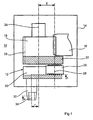
- Figure 1 is a schematic view of a device 10 with gear 12, which is arranged in a housing 14 of the swing door drive is.
- gear 12 which is arranged in a housing 14 of the swing door drive is.
- the reproduction of the known parts of the rotary leaf drive have been dispensed with.
- the gear 12 cooperates with a rack 16.
- a rack 16 engages a pinion 18 which is fixed with a driving roller 20 carrying driver 22 is connected, wherein the axis of rotation 24th of the pinion 18 and the axis of rotation of the driver 22 are identical.
- the axis of rotation 26 of the driving roller 20 is in one with the axis of rotation 24 Distance E arranged so that the axis of rotation 26 the pitch circle 28 of the Ritzels 18 cuts.
- the axes of rotation 24 and 26 are parallel to each other aligned.
- the driving roller 20 is arranged between a guide 30 which is fixed connected to an output shaft 32 protruding from the housing 14 is.
- the axis of rotation 34 of the output shaft 32 and the axis of rotation of the Guide 30 are therefore identical.
- the axis of rotation 34 of the output shaft 32 and the guide 30 is to the axis of rotation 24 of the pinion 18 and the driver 22 arranged at a distance F.
- a slide rail arm not shown, will act on the output shaft 32.
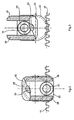
- the output shaft 32 With the opening of a door leaf on which, for example, the swing door drive is attached, the output shaft 32 is rotated. About a tour which consists of two guide rails 36 and 38, see Figures 2 and 3, the idler roller 20 is moved, i. H. by opening the Door is transmitted to the output shaft 32 and the guide 30 force via the guide 30 to the driver roller 20 and thus to the driver 22 and the pinion 18 transmitted. The driving roller 20 is thereby guided translationally relative to the guide 30. The pinion 18 moves the Rack 16 when opening and closing by the drive motor control based on a sensor signal.
- Figures 2 and 3 change with the rotation the output shaft 32 and thus the driver 22 with the pinion 18th the relative position of the axis of rotation 26 of the driving roller 20 to the axis of rotation 34 of the output shaft 32.
- Figures 2 and 3 show rotated by 180 ° Positions of the transmission 12 according to the partial sectional view according to the line A-A.
- the maximum distance of the axis of rotation 26 of the driving roller 20 of the axis of rotation 34 of the output shaft 32 is in Figure 2 and the minimum distance of the axis of rotation 26 of the driving roller 20 from the axis of rotation 34 of the output shaft 32 is shown in Figure 3.
- the gear ratio of the transmission 12 is determined by the Diameter of the pitch circle 28, the pinion 18, the distance F Axis of rotation 34, the output shaft 32 from the axis of rotation 24 of the pinion 18, and from the distance E of the axis of rotation 26 of the driving roller 20 to Axis of rotation 24 of the pinion 18 is determined.
- the force curve is over the opening angle affects the door leaf and can be done in a simple manner be determined.
Landscapes
- Power-Operated Mechanisms For Wings (AREA)
- Transmission Devices (AREA)
- Lock And Its Accessories (AREA)
Abstract
Description
- Figur 1:
- Eine schematische Schnittansicht des Getriebes des Drehtürantriebes.
- Figur 2 und Figur 3:
- Eine Ansicht gemäß der Linie A-A von Figur 1 in um 180° gedrehten Stellungen.
- 10
- Vorrichtung
- 12
- Getriebe
- 14
- Gehäuse
- 16
- Zahnstange
- 18
- Ritzel
- 20
- Mitnehmerrolle
- 22
- Mitnehmer
- 24
- Drehachse
- 26
- Drehachse
- 28
- Wälzkreis
- 30
- Führung
- 32
- Abtriebswelle
- 34
- Drehachse
- 36
- Führungsschiene - links
- 38
- Führungsschiene - rechts
- E
- Abstand (Drehachse 24 zur Drehachse 26)
- F
- Abstand (Drehachse 34 zur Drehachse 24)
Claims (10)
- Drehtürantrieb mit einer elektromechanischen oder elektrohydraulischen Antriebsvorrichtung, die das für das Öffnen und Schließen eines angeschlossenen Drehflügels nötige Öffnungs- bzw. und/oder Schließmoment liefert, wobei eine elektronische Regelung /Steuerung mit mindestens einem Speicher und mindestens einem Mikroprozessor aufgrund von Sensorsignalen das Öffnen bzw. das Schließen über eine Abtriebswelle bewirkt, die mit einem Gestänge oder einem Betätigungsarm erzeugt wird, dadurch gekennzeichnet, daß zwischen der Abtriebswelle (32) des Drehtürantriebes und dem Gestänge bzw. dem Betätigungsarm eine Vorrichtung (10) vorhanden ist, die eine Veränderung des Öffnungs- und/oder des Schließmomentes über den Drehwinkel des angeschlossenen Drehflügels bewirkt.
- Drehtürantrieb mit einer elektromechanischen oder elektrohydraulischen Antriebsvorrichtung, die das für das Öffnen und Schließen eines angeschlossenen Drehflügels nötige Öffnungsmoment liefert, wobei eine elektronische Regelungssteuerung mit mindestens einem Speicher und mindestens einem Mikroprozessor aufgrund von Sensorsignalen das Öffnungsmoment über eine Abtriebswelle liefert und mit der Antriebsvorrichtung direkt oder indirekt ein Getriebe verbunden ist, das mit einem Achsaustritt eines Türschließers verbunden ist und über die Abtriebsachse des Türschließers mit einem Gestänge oder einem Betätigungsarm in Verbindung steht, dadurch gekennzeichnet, daß zwischen der Abtriebsachse des Türschließers und dem Gestänge bzw. dem Betätigungsarm eine Vorrichtung (10) vorhanden ist, die eine Veränderung des Öffnungs- und/oder des Schließmomentes über den Drehwinkel des Drehflügels bewirkt.
- Drehtürantrieb nach Anspruch 1 und 2, dadurch gekennzeichnet, daß die Vorrichtung (10) ein Getriebe (12) ist, das unterschiedliche Übersetzungsverhältnisse aufweist.
- Drehtürantrieb nach Anspruch 1 und 3, dadurch gekennzeichnet, daß das sich über den Öffnungswinkel der Tür in seinem Übersetzungsverhältnis ändernde Getriebe (12) eine mit der Abtriebswelle (32) verbundene Führung (30) und eine relativ zu der Führung (30) und in dieser translatorisch bewegbare Mitnehmerrolle (20) umfaßt, die mit einem mit einer mit der elektromechanisch oder elektrohydraulischen Vorrichtung in Verbindung stehenden Zahnstange (16) eingreifendes Ritzel verbunden ist, wobei die Drehachse (34) der Abtriebswelle (32) zur Drehachse (24) des Ritzels (18) und die Drehachse (26) der Mitnehmerrolle (20) zu der Drehachse (24) des Ritzels (18) in vorbestimmten Abständen (E und F) voneinander angeordnet sind, derart, daß beim Verdrehen des Ritzels (18), in Folge des sich dabei ändernden Achsabstandes zwischen Abtriebswelle (32) und Mitnehmerrolle (20), sich das Übersetzungsverhältnis der Abtriebswelle (32) ändert.
- Drehtürantrieb nach Anspruch 2, dadurch gekennzeichnet, daß das sich über den Öffnungswinkel der Tür in seinem Übersetzungsverhältnis ändernde Getriebe (12) eine mit der Abtriebswelle (32) verbundene Führung (30) und eine relativ zu der Führung (30) und in dieser translatorisch bewegbare Mitnehmerrolle (20) umfaßt, die mit eine mit der Federspannung des Türschließers in Verbindung stehenden Zahnstange (16) eingreifendes Ritzel (18) verbunden ist, wobei die Drehachse (34) der Abtriebswelle (32) zur Drehachse (24) des Ritzels(18) und die Drehachse (26) der Mitnehmerrolle (20) zu der Drehachse (24) des Ritzels (18) in vorbestimmten Abständen (E und F) voneinander angeordnet sind, derart, daß beim Verdrehen des Ritzels (18), in Folge des sich dabei ändernden Achsabstandes zwischen Abtriebswelle (32) und Mitnehmerrolle (20), sich das Übersetzungsverhältnis der Abtriebswelle (32) ändert.
- Drehtürantrieb nach den Ansprüchen 4 und 5, dadurch gekennzeichnet, daß die Drehachse (26) der Mitnehmerrolle (20) den Wälzkreis (28) des Ritzels (18) schneidet und parallel zur Drehachse (24) des Ritzels (18) ausgerichtet ist.
- Drehtürantrieb nach den Ansprüchen 3 bis 5, dadurch gekennzeichnet, daß das Übersetzungsverhältnis des Getriebes (12) durch des Durchmesser des Wälzkreises (28), des Ritzels (18), den Abstand F der Drehachse (34), der Abtriebswelle (32) von der Drehachse (24) des Ritzels (18) sowie von dem Abstand E der Drehachse (24) der Mitnehmerrolle (20) zur Drehachse (24) des Ritzels (18) bestimmt ist.
- Drehtürantrieb nach einem der vorhergehenden Ansprüche, gekennzeichnet durch eine Ausbildung des Drehtürantriebes mit einem zwischen einem Anlenkpunkt des drehbeweglichen Drehflügels der zugeordneten Tür und einem weiteren Anlenkpunkt außerhalb des Türblattes über den Drehbereich sich ändernden wirksamen Hebelarm, der an die Abtriebswelle (32) angreift.
- Drehtürantrieb nach Anspruch 8, dadurch gekennzeichnet, daß der wirksame Hebelarm durch ein Gleitschienengestänge gebildet wird.
- Drehtürantrieb nach Anspruch 8, dadurch gekennzeichnet, daß der wirksame Hebelarm durch ein Kniehebelgestänge gebildet wird.
Applications Claiming Priority (2)
| Application Number | Priority Date | Filing Date | Title |
|---|---|---|---|
| DE19901033 | 1999-01-14 | ||
| DE19901033A DE19901033C2 (de) | 1999-01-14 | 1999-01-14 | Drehtürantrieb |
Publications (3)
| Publication Number | Publication Date |
|---|---|
| EP1020603A2 true EP1020603A2 (de) | 2000-07-19 |
| EP1020603A3 EP1020603A3 (de) | 2003-05-14 |
| EP1020603B1 EP1020603B1 (de) | 2008-03-26 |
Family
ID=7894138
Family Applications (1)
| Application Number | Title | Priority Date | Filing Date |
|---|---|---|---|
| EP99120290A Expired - Lifetime EP1020603B1 (de) | 1999-01-14 | 1999-10-12 | Drehtürantrieb |
Country Status (6)
| Country | Link |
|---|---|
| US (1) | US6262548B1 (de) |
| EP (1) | EP1020603B1 (de) |
| AT (1) | ATE390535T1 (de) |
| DE (2) | DE19901033C2 (de) |
| DK (1) | DK1020603T3 (de) |
| ES (1) | ES2304801T3 (de) |
Cited By (1)
| Publication number | Priority date | Publication date | Assignee | Title |
|---|---|---|---|---|
| EP1020602A3 (de) * | 1999-01-14 | 2003-05-14 | DORMA GmbH + Co. KG | Drehtürantrieb |
Families Citing this family (15)
| Publication number | Priority date | Publication date | Assignee | Title |
|---|---|---|---|---|
| US6628095B1 (en) * | 1998-11-10 | 2003-09-30 | Tyco Electronics Logistics A.G. | Actuator for remote operation of a circuit breaker |
| DE10107051C2 (de) * | 2001-02-13 | 2003-06-26 | Dorma Gmbh & Co Kg | Elektromechanischer Drehflügelantrieb |
| AU2002238544B8 (en) * | 2001-02-13 | 2008-05-29 | Dorma Gmbh + Co. Kg | Electromechanical hinged wing drive |
| DE10300822A1 (de) * | 2003-01-10 | 2004-08-05 | Dorma Gmbh + Co. Kg | Türflügelantrieb |
| JP4784813B2 (ja) * | 2004-12-21 | 2011-10-05 | 日本発條株式会社 | ドアクローザ |
| EP1959082A4 (de) * | 2005-11-08 | 2013-10-30 | Nifco Inc | Einziehmechanismus |
| US7865999B2 (en) * | 2007-02-02 | 2011-01-11 | Yale Security Inc. | Door motion controller assembly |
| US7971316B2 (en) * | 2007-04-24 | 2011-07-05 | Yale Security Inc. | Door closer assembly |
| DE202007012603U1 (de) * | 2007-09-07 | 2009-01-22 | Hettich-Oni Gmbh & Co. Kg | Türscharnier eines Haushaltsgerätes |
| US8966712B1 (en) * | 2013-12-31 | 2015-03-03 | Chia-Chu Yu | Door operator |
| DE102014212553B3 (de) * | 2014-06-30 | 2015-07-09 | Siemens Aktiengesellschaft | Modulares Türantriebssteuerungssystem sowie modulares Türantriebssystem |
| AT517343B1 (de) * | 2015-06-29 | 2017-01-15 | Blum Gmbh Julius | Ausstoßvorrichtung für eine Falttür oder Falt-Schiebe-Tür |
| DE102016200019A1 (de) * | 2016-01-05 | 2017-07-06 | Stabilus Gmbh | Scherenantrieb |
| US10953788B2 (en) | 2016-05-21 | 2021-03-23 | JST Performance, LLC | Method and apparatus for vehicular light fixtures |
| US10337223B2 (en) | 2016-11-23 | 2019-07-02 | Kohler Co. | Shower door hinge assembly |
Citations (8)
| Publication number | Priority date | Publication date | Assignee | Title |
|---|---|---|---|---|
| US1684704A (en) | 1926-01-06 | 1928-09-18 | Louie E Hubbell | Door control |
| US2256613A (en) | 1939-04-29 | 1941-09-23 | Nat Pneumatic Co | Door operating mechanism |
| US4333270A (en) | 1980-02-22 | 1982-06-08 | Besam-Eads, Inc. | Automatic door operator |
| DE3202930A1 (de) | 1982-01-29 | 1983-08-11 | Geze Gmbh, 7250 Leonberg | Elektromechanischer antrieb fuer schwenkfluegel von tueren o.dgl. |
| DE3730114A1 (de) | 1986-11-05 | 1988-05-11 | Protor Ag | Vorrichtung zum oeffnen und schliessen von tueren |
| DE4124282C2 (de) | 1991-07-23 | 1993-05-13 | Dorma Gmbh + Co. Kg, 5828 Ennepetal, De | |
| DE3645313C2 (de) | 1986-04-28 | 1996-07-18 | Geze Grundstueck Beteiligung | Türschließer |
| WO1998011578A1 (en) | 1996-09-13 | 1998-03-19 | Ericsson Inc. | Electronic device casing including living spring button and method |
Family Cites Families (6)
| Publication number | Priority date | Publication date | Assignee | Title |
|---|---|---|---|---|
| FR1510056A (fr) * | 1966-12-06 | 1968-01-19 | Levasseur Ets | Perfectionnements aux ferme-portes automatiques |
| US4339843A (en) * | 1978-03-20 | 1982-07-20 | Reading-Dorma Closer Corporation | Door closer with assist or door operating features |
| WO1989000262A1 (en) | 1987-07-08 | 1989-01-12 | Vaso Products Australia Pty. Limited | Deformable valve |
| SE460612B (sv) * | 1988-05-16 | 1989-10-30 | Soederhamn Innovation Ab | Oeppnarmekanism foer doerrstaengare |
| DE4100335C2 (de) * | 1991-01-08 | 1995-11-23 | Tuerautomation Fehraltorf Ag F | Elektromechanischer Drehflügelantrieb für Schwenkflügel von Türen oder dergleichen |
| DE19901229C2 (de) * | 1999-01-14 | 2002-08-08 | Dorma Gmbh & Co Kg | Drehtürantrieb |
-
1999
- 1999-01-14 DE DE19901033A patent/DE19901033C2/de not_active Expired - Fee Related
- 1999-10-12 DE DE59914709T patent/DE59914709D1/de not_active Expired - Lifetime
- 1999-10-12 EP EP99120290A patent/EP1020603B1/de not_active Expired - Lifetime
- 1999-10-12 ES ES99120290T patent/ES2304801T3/es not_active Expired - Lifetime
- 1999-10-12 DK DK99120290T patent/DK1020603T3/da active
- 1999-10-12 AT AT99120290T patent/ATE390535T1/de not_active IP Right Cessation
-
2000
- 2000-01-13 US US09/482,365 patent/US6262548B1/en not_active Expired - Fee Related
Patent Citations (8)
| Publication number | Priority date | Publication date | Assignee | Title |
|---|---|---|---|---|
| US1684704A (en) | 1926-01-06 | 1928-09-18 | Louie E Hubbell | Door control |
| US2256613A (en) | 1939-04-29 | 1941-09-23 | Nat Pneumatic Co | Door operating mechanism |
| US4333270A (en) | 1980-02-22 | 1982-06-08 | Besam-Eads, Inc. | Automatic door operator |
| DE3202930A1 (de) | 1982-01-29 | 1983-08-11 | Geze Gmbh, 7250 Leonberg | Elektromechanischer antrieb fuer schwenkfluegel von tueren o.dgl. |
| DE3645313C2 (de) | 1986-04-28 | 1996-07-18 | Geze Grundstueck Beteiligung | Türschließer |
| DE3730114A1 (de) | 1986-11-05 | 1988-05-11 | Protor Ag | Vorrichtung zum oeffnen und schliessen von tueren |
| DE4124282C2 (de) | 1991-07-23 | 1993-05-13 | Dorma Gmbh + Co. Kg, 5828 Ennepetal, De | |
| WO1998011578A1 (en) | 1996-09-13 | 1998-03-19 | Ericsson Inc. | Electronic device casing including living spring button and method |
Cited By (1)
| Publication number | Priority date | Publication date | Assignee | Title |
|---|---|---|---|---|
| EP1020602A3 (de) * | 1999-01-14 | 2003-05-14 | DORMA GmbH + Co. KG | Drehtürantrieb |
Also Published As
| Publication number | Publication date |
|---|---|
| EP1020603A3 (de) | 2003-05-14 |
| DE59914709D1 (de) | 2008-05-08 |
| US6262548B1 (en) | 2001-07-17 |
| ES2304801T3 (es) | 2008-10-16 |
| ATE390535T1 (de) | 2008-04-15 |
| EP1020603B1 (de) | 2008-03-26 |
| DE19901033A1 (de) | 2000-07-27 |
| DK1020603T3 (da) | 2008-07-28 |
| DE19901033C2 (de) | 2002-08-08 |
Similar Documents
| Publication | Publication Date | Title |
|---|---|---|
| DE3816175C2 (de) | ||
| EP1020602B1 (de) | Drehtürantrieb | |
| EP1020603B1 (de) | Drehtürantrieb | |
| DE19500944C2 (de) | Antrieb und Schließfedereinrichtung für einen Flügel einer Tür, Fenster oder dergleichen | |
| EP2047050A1 (de) | Türantrieb mit während der türbewegung veränderbarer federvorspannung | |
| DE10336075B4 (de) | Antrieb für einen Flügel, insbesondere Drehantrieb für eine Tür, ein Fenster oder dergleichen | |
| EP0243786A1 (de) | Türschliesser | |
| DE102004027420A1 (de) | Motorische Kraftfahrzeugkomponente | |
| DE10336074B3 (de) | Antrieb für einen Flügel, insbesondere Drehantrieb für eine Tür, ein Fenster oder dergleichen | |
| DE102004061621A1 (de) | Türantrieb, insbesondere Drehtürantrieb | |
| EP1582668A2 (de) | Schliesskeil-Antriebsbaugruppe für ein Kraftfahrzeugschloss | |
| DE19513435A1 (de) | Türschließer | |
| DE102006011083A1 (de) | Kraftfahrzeugschloß | |
| EP0446655B1 (de) | Selbsthemmendes Schneckenradgetriebe in einem Schnelllauftorantrieb | |
| DE19831069A1 (de) | Fahrzeug, bei dem zwei Rädern je ein Antriebsmotor mit einem Reduktionsgetriebe zugeordnet sind | |
| EP1862631A2 (de) | Antriebsanordnung zur motorischen Verstellung eines Verschlußelements eines Kraftfahrzeugs | |
| DE19532263B4 (de) | Vorrichtung zur Schließfolgeregelung für zweiflügelige Türen | |
| EP1467054B1 (de) | Türschliesser | |
| EP1288418A2 (de) | Beschlagseinheit für ein Kipp- oder Drehkippfenster | |
| DE4014507A1 (de) | Lastverstelleinrichtung | |
| DE19901234C1 (de) | Türschließer | |
| EP1409827B1 (de) | Hydraulischer drehflügelantrieb | |
| DE102009000542B4 (de) | Antrieb für einen Flügel einer Tür | |
| DE102005047297B3 (de) | Antriebsvorrichtung für einen Verdeckkastendeckel eines Kraftfahrzeugs | |
| EP0709536A1 (de) | Antrieb |
Legal Events
| Date | Code | Title | Description |
|---|---|---|---|
| PUAI | Public reference made under article 153(3) epc to a published international application that has entered the european phase |
Free format text: ORIGINAL CODE: 0009012 |
|
| AK | Designated contracting states |
Kind code of ref document: A2 Designated state(s): AT BE CH CY DE DK ES FI FR GB GR IE IT LI LU MC NL PT SE |
|
| AX | Request for extension of the european patent |
Free format text: AL;LT;LV;MK;RO;SI |
|
| PUAL | Search report despatched |
Free format text: ORIGINAL CODE: 0009013 |
|
| AK | Designated contracting states |
Designated state(s): AT BE CH CY DE DK ES FI FR GB GR IE IT LI LU MC NL PT SE |
|
| AX | Request for extension of the european patent |
Extension state: AL LT LV MK RO SI |
|
| 17P | Request for examination filed |
Effective date: 20031114 |
|
| AKX | Designation fees paid |
Designated state(s): AT BE CH CY DE DK ES FI FR GB GR IE IT LI LU MC NL PT SE |
|
| 17Q | First examination report despatched |
Effective date: 20070212 |
|
| GRAP | Despatch of communication of intention to grant a patent |
Free format text: ORIGINAL CODE: EPIDOSNIGR1 |
|
| GRAS | Grant fee paid |
Free format text: ORIGINAL CODE: EPIDOSNIGR3 |
|
| GRAA | (expected) grant |
Free format text: ORIGINAL CODE: 0009210 |
|
| AK | Designated contracting states |
Kind code of ref document: B1 Designated state(s): AT BE CH CY DE DK ES FI FR GB GR IE IT LI LU MC NL PT SE |
|
| REG | Reference to a national code |
Ref country code: GB Ref legal event code: FG4D Free format text: NOT ENGLISH |
|
| REG | Reference to a national code |
Ref country code: IE Ref legal event code: FG4D Free format text: LANGUAGE OF EP DOCUMENT: GERMAN Ref country code: CH Ref legal event code: EP |
|
| REF | Corresponds to: |
Ref document number: 59914709 Country of ref document: DE Date of ref document: 20080508 Kind code of ref document: P |
|
| REG | Reference to a national code |
Ref country code: SE Ref legal event code: TRGR |
|
| REG | Reference to a national code |
Ref country code: DK Ref legal event code: T3 |
|
| REG | Reference to a national code |
Ref country code: CH Ref legal event code: NV Representative=s name: BOVARD AG PATENTANWAELTE |
|
| NLV1 | Nl: lapsed or annulled due to failure to fulfill the requirements of art. 29p and 29m of the patents act | ||
| REG | Reference to a national code |
Ref country code: ES Ref legal event code: FG2A Ref document number: 2304801 Country of ref document: ES Kind code of ref document: T3 |
|
| REG | Reference to a national code |
Ref country code: IE Ref legal event code: FD4D |
|
| PG25 | Lapsed in a contracting state [announced via postgrant information from national office to epo] |
Ref country code: PT Free format text: LAPSE BECAUSE OF FAILURE TO SUBMIT A TRANSLATION OF THE DESCRIPTION OR TO PAY THE FEE WITHIN THE PRESCRIBED TIME-LIMIT Effective date: 20080901 |
|
| PG25 | Lapsed in a contracting state [announced via postgrant information from national office to epo] |
Ref country code: NL Free format text: LAPSE BECAUSE OF FAILURE TO SUBMIT A TRANSLATION OF THE DESCRIPTION OR TO PAY THE FEE WITHIN THE PRESCRIBED TIME-LIMIT Effective date: 20080326 |
|
| ET | Fr: translation filed | ||
| PG25 | Lapsed in a contracting state [announced via postgrant information from national office to epo] |
Ref country code: IE Free format text: LAPSE BECAUSE OF FAILURE TO SUBMIT A TRANSLATION OF THE DESCRIPTION OR TO PAY THE FEE WITHIN THE PRESCRIBED TIME-LIMIT Effective date: 20080326 |
|
| PGFP | Annual fee paid to national office [announced via postgrant information from national office to epo] |
Ref country code: DK Payment date: 20081015 Year of fee payment: 10 Ref country code: CH Payment date: 20081015 Year of fee payment: 10 |
|
| PLBE | No opposition filed within time limit |
Free format text: ORIGINAL CODE: 0009261 |
|
| STAA | Information on the status of an ep patent application or granted ep patent |
Free format text: STATUS: NO OPPOSITION FILED WITHIN TIME LIMIT |
|
| PGFP | Annual fee paid to national office [announced via postgrant information from national office to epo] |
Ref country code: FI Payment date: 20081015 Year of fee payment: 10 Ref country code: ES Payment date: 20081027 Year of fee payment: 10 |
|
| 26N | No opposition filed |
Effective date: 20081230 |
|
| PGFP | Annual fee paid to national office [announced via postgrant information from national office to epo] |
Ref country code: IT Payment date: 20081025 Year of fee payment: 10 Ref country code: SE Payment date: 20081014 Year of fee payment: 10 |
|
| BERE | Be: lapsed |
Owner name: DORMA G.M.B.H. + CO. KG Effective date: 20081031 |
|
| PGFP | Annual fee paid to national office [announced via postgrant information from national office to epo] |
Ref country code: FR Payment date: 20081014 Year of fee payment: 10 |
|
| PG25 | Lapsed in a contracting state [announced via postgrant information from national office to epo] |
Ref country code: MC Free format text: LAPSE BECAUSE OF NON-PAYMENT OF DUE FEES Effective date: 20081031 |
|
| PGFP | Annual fee paid to national office [announced via postgrant information from national office to epo] |
Ref country code: GB Payment date: 20081021 Year of fee payment: 10 |
|
| PG25 | Lapsed in a contracting state [announced via postgrant information from national office to epo] |
Ref country code: BE Free format text: LAPSE BECAUSE OF NON-PAYMENT OF DUE FEES Effective date: 20081031 Ref country code: CY Free format text: LAPSE BECAUSE OF FAILURE TO SUBMIT A TRANSLATION OF THE DESCRIPTION OR TO PAY THE FEE WITHIN THE PRESCRIBED TIME-LIMIT Effective date: 20080326 |
|
| PG25 | Lapsed in a contracting state [announced via postgrant information from national office to epo] |
Ref country code: AT Free format text: LAPSE BECAUSE OF NON-PAYMENT OF DUE FEES Effective date: 20081012 |
|
| REG | Reference to a national code |
Ref country code: CH Ref legal event code: PL |
|
| EUG | Se: european patent has lapsed | ||
| REG | Reference to a national code |
Ref country code: DK Ref legal event code: EBP |
|
| PG25 | Lapsed in a contracting state [announced via postgrant information from national office to epo] |
Ref country code: LU Free format text: LAPSE BECAUSE OF NON-PAYMENT OF DUE FEES Effective date: 20081012 |
|
| REG | Reference to a national code |
Ref country code: FR Ref legal event code: ST Effective date: 20100630 |
|
| PG25 | Lapsed in a contracting state [announced via postgrant information from national office to epo] |
Ref country code: FR Free format text: LAPSE BECAUSE OF NON-PAYMENT OF DUE FEES Effective date: 20091102 |
|
| PG25 | Lapsed in a contracting state [announced via postgrant information from national office to epo] |
Ref country code: FI Free format text: LAPSE BECAUSE OF NON-PAYMENT OF DUE FEES Effective date: 20091012 |
|
| PG25 | Lapsed in a contracting state [announced via postgrant information from national office to epo] |
Ref country code: LI Free format text: LAPSE BECAUSE OF NON-PAYMENT OF DUE FEES Effective date: 20091031 Ref country code: GR Free format text: LAPSE BECAUSE OF FAILURE TO SUBMIT A TRANSLATION OF THE DESCRIPTION OR TO PAY THE FEE WITHIN THE PRESCRIBED TIME-LIMIT Effective date: 20080627 Ref country code: CH Free format text: LAPSE BECAUSE OF NON-PAYMENT OF DUE FEES Effective date: 20091031 |
|
| PG25 | Lapsed in a contracting state [announced via postgrant information from national office to epo] |
Ref country code: GB Free format text: LAPSE BECAUSE OF NON-PAYMENT OF DUE FEES Effective date: 20091012 |
|
| PG25 | Lapsed in a contracting state [announced via postgrant information from national office to epo] |
Ref country code: DK Free format text: LAPSE BECAUSE OF NON-PAYMENT OF DUE FEES Effective date: 20091031 |
|
| PGFP | Annual fee paid to national office [announced via postgrant information from national office to epo] |
Ref country code: DE Payment date: 20101022 Year of fee payment: 12 |
|
| REG | Reference to a national code |
Ref country code: ES Ref legal event code: FD2A Effective date: 20110328 |
|
| PG25 | Lapsed in a contracting state [announced via postgrant information from national office to epo] |
Ref country code: IT Free format text: LAPSE BECAUSE OF NON-PAYMENT OF DUE FEES Effective date: 20091012 |
|
| PG25 | Lapsed in a contracting state [announced via postgrant information from national office to epo] |
Ref country code: SE Free format text: LAPSE BECAUSE OF NON-PAYMENT OF DUE FEES Effective date: 20091013 |
|
| PG25 | Lapsed in a contracting state [announced via postgrant information from national office to epo] |
Ref country code: ES Free format text: LAPSE BECAUSE OF NON-PAYMENT OF DUE FEES Effective date: 20110314 |
|
| PG25 | Lapsed in a contracting state [announced via postgrant information from national office to epo] |
Ref country code: ES Free format text: LAPSE BECAUSE OF NON-PAYMENT OF DUE FEES Effective date: 20091013 |
|
| PG25 | Lapsed in a contracting state [announced via postgrant information from national office to epo] |
Ref country code: DE Free format text: LAPSE BECAUSE OF NON-PAYMENT OF DUE FEES Effective date: 20120501 |
|
| REG | Reference to a national code |
Ref country code: DE Ref legal event code: R119 Ref document number: 59914709 Country of ref document: DE Effective date: 20120501 |