EP1020672A1 - Collier de serrage d'une ligne de transmission - Google Patents
Collier de serrage d'une ligne de transmission Download PDFInfo
- Publication number
- EP1020672A1 EP1020672A1 EP00100368A EP00100368A EP1020672A1 EP 1020672 A1 EP1020672 A1 EP 1020672A1 EP 00100368 A EP00100368 A EP 00100368A EP 00100368 A EP00100368 A EP 00100368A EP 1020672 A1 EP1020672 A1 EP 1020672A1
- Authority
- EP
- European Patent Office
- Prior art keywords
- transmission line
- hanger
- section
- aperture
- line hanger
- Prior art date
- Legal status (The legal status is an assumption and is not a legal conclusion. Google has not performed a legal analysis and makes no representation as to the accuracy of the status listed.)
- Granted
Links
- 230000005540 biological transmission Effects 0.000 title claims abstract description 176
- 230000014759 maintenance of location Effects 0.000 claims abstract description 19
- 230000033001 locomotion Effects 0.000 claims abstract description 15
- 230000001681 protective effect Effects 0.000 claims abstract description 5
- 238000000034 method Methods 0.000 claims description 23
- 239000002184 metal Substances 0.000 claims description 5
- 230000000149 penetrating effect Effects 0.000 claims description 4
- 238000003825 pressing Methods 0.000 claims description 2
- 210000003811 finger Anatomy 0.000 description 36
- 238000009434 installation Methods 0.000 description 11
- 230000008569 process Effects 0.000 description 5
- 238000007373 indentation Methods 0.000 description 4
- 238000003780 insertion Methods 0.000 description 3
- 230000037431 insertion Effects 0.000 description 3
- 238000005246 galvanizing Methods 0.000 description 2
- 238000012986 modification Methods 0.000 description 2
- 230000004048 modification Effects 0.000 description 2
- 238000004080 punching Methods 0.000 description 2
- 239000004698 Polyethylene Substances 0.000 description 1
- 230000009471 action Effects 0.000 description 1
- 230000008859 change Effects 0.000 description 1
- 210000004247 hand Anatomy 0.000 description 1
- 230000005571 horizontal transmission Effects 0.000 description 1
- 239000000314 lubricant Substances 0.000 description 1
- 230000007246 mechanism Effects 0.000 description 1
- 239000004033 plastic Substances 0.000 description 1
- 229920003023 plastic Polymers 0.000 description 1
- -1 polyethylene Polymers 0.000 description 1
- 229920000573 polyethylene Polymers 0.000 description 1
- 230000004044 response Effects 0.000 description 1
- 239000007779 soft material Substances 0.000 description 1
- 229910001220 stainless steel Inorganic materials 0.000 description 1
- 239000010935 stainless steel Substances 0.000 description 1
- 210000003813 thumb Anatomy 0.000 description 1
Images


Classifications
-
- H—ELECTRICITY
- H02—GENERATION; CONVERSION OR DISTRIBUTION OF ELECTRIC POWER
- H02G—INSTALLATION OF ELECTRIC CABLES OR LINES, OR OF COMBINED OPTICAL AND ELECTRIC CABLES OR LINES
- H02G7/00—Overhead installations of electric lines or cables
- H02G7/05—Suspension arrangements or devices for electric cables or lines
-
- F—MECHANICAL ENGINEERING; LIGHTING; HEATING; WEAPONS; BLASTING
- F16—ENGINEERING ELEMENTS AND UNITS; GENERAL MEASURES FOR PRODUCING AND MAINTAINING EFFECTIVE FUNCTIONING OF MACHINES OR INSTALLATIONS; THERMAL INSULATION IN GENERAL
- F16L—PIPES; JOINTS OR FITTINGS FOR PIPES; SUPPORTS FOR PIPES, CABLES OR PROTECTIVE TUBING; MEANS FOR THERMAL INSULATION IN GENERAL
- F16L3/00—Supports for pipes, cables or protective tubing, e.g. hangers, holders, clamps, cleats, clips, brackets
- F16L3/08—Supports for pipes, cables or protective tubing, e.g. hangers, holders, clamps, cleats, clips, brackets substantially surrounding the pipe, cable or protective tubing
- F16L3/12—Supports for pipes, cables or protective tubing, e.g. hangers, holders, clamps, cleats, clips, brackets substantially surrounding the pipe, cable or protective tubing comprising a member substantially surrounding the pipe, cable or protective tubing
-
- H—ELECTRICITY
- H02—GENERATION; CONVERSION OR DISTRIBUTION OF ELECTRIC POWER
- H02G—INSTALLATION OF ELECTRIC CABLES OR LINES, OR OF COMBINED OPTICAL AND ELECTRIC CABLES OR LINES
- H02G3/00—Installations of electric cables or lines or protective tubing therefor in or on buildings, equivalent structures or vehicles
- H02G3/30—Installations of cables or lines on walls, floors or ceilings
- H02G3/32—Installations of cables or lines on walls, floors or ceilings using mounting clamps
Definitions
- This invention relates generally to transmission lines, and in particular to transmission line hangers for supporting transmission lines used in antenna systems.
- Transmission line hangers are used to support transmission lines. Transmission lines are supported by attaching them to supporting structures by transmission line hangers. The most extensive use of hangers is in connection with coaxial cables, such as those disclosed in U.S. Patent No. 5,334,051 (Devine et al.) and 5,167,533 (Rauwolf). Coaxial cables are extensively used for carrying a variety of electromagnetic signals. In most uses, the cables need to be attached to a supporting structure along most of their lengths.
- Transmission line hangers are also used for supporting waveguides which carry electromagnetic signals from transmitting or receiving equipment in an equipment shelter to an antenna mounted on a tall tower.
- a large number of hangers are required to support a waveguide beneath a horizontal waveguide bridge extending between the shelter and the base of the tower and to support the waveguide on the tower as the wave guide extends upwardly to the antenna.
- An even larger number of hangers are required where separate waveguides extend to several antennas on a signal tower.
- Commercially available waveguides have a variety of cross-sectional shapes. For example, a variety of waveguide shapes are disclosed in U.S. Patent Nos. 3,822,411 (Merle) and 4,047,133 (Merle).
- a typical hanger for elliptical-shaped waveguides includes a generally U-shaped clip adapted to be attached to a support member on the bridge or the tower by a bolt extending through a hole in the support member and held in place by a nut and lock washer. After the hangers have been attached to the support members, the waveguide is strung along the bridge, up the tower and clamped between the legs of each U-shaped hanger by tightening a clamping screw which extends between the legs. A considerable amount of installation time is required, first to attach the large number of hangers to the bridge and the tower and then to clamp the waveguide within the hangers. In addition, a large amount of auxiliary hardware (e.g ., screws, bolts, nuts and washers) is required along with the hangers themselves.
- auxiliary hardware e.g ., screws, bolts, nuts and washers
- a spring hanger system for supporting a VHF circular waveguide is disclosed in U.S. Patent No. 4,654,612 (Smith).
- a variety of prior hangers for microwave transmission lines are disclosed in Andrew Corporation Catalog #36.
- An improved waveguide hanger is disclosed in U.S. Patent No. 4,763,132 (Juds et al.).
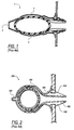
- the waveguide hanger disclosed in the Juds et al. patent is in the form of a resiliently yieldable and generally U-shaped clip 1, illustrated in FIG. 1, that is adapted to be slipped over an elliptical waveguide and snapped into a supporting member.
- the clip includes a hinge portion 2 that extends between the legs 3 of the clip 1.
- the cable hanger 200 disclosed there includes a hinge section 320, a cable retention section 340, and a structure attachment section 360 having two locking members 580 that each include a pair of concave locking barbs 600.
- Cable hangers that include hinges can only accommodate a limited range of cable diameters. The maximum cable diameter accepted by such cable hangers is limited by the maximum circumference of the cable retention section.
- Prior cable hangers such as Nelson and Juds et al., also place the cable retention section close to the attachment section.
- the attachment section is traditionally short in length. This makes the attachment section rigid and non-compliant which makes installation of such hangers difficult especially where a large diameter cable is being installed on a tower or where the weather conditions limit manual dexterity, e.g ., cold weather. In such situations, tools may be required to squeeze the hanger into the tower aperture. The use of tools is undesirable especially where a cable is being installed on a high tower.
- a transmission line hanger for securing a transmission line to a supporting structure having an aperture defined by a wall.
- the transmission line hanger includes a partially cylindrical member for accommodating a transmission line.
- the partially cylindrical member includes a first leg and a second leg each respectively extending from the partially cylindrical member.
- the first and second legs allow the hanger to accommodate various sizes of transmission lines.
- the first and second legs each include a first section for contacting the wall of the aperture at one of a pair of contact points, and a second section extending from the first section and forming a locking barb configured to lock against the supporting structure once the locking barb is inserted through the aperture.
- a transmission line hanger for securing a transmission line having a protective jacket to a supporting structure having an aperture defined by a wall.
- the transmission line hanger includes a transmission line retention section for retaining a transmission line.
- the transmission line hanger further includes an extended section extending from the retention section.
- the extended section includes a spring finger flexibly connected thereto, and projecting inwardly therefrom.
- the spring finger is configured to penetrate into the jacket once the transmission line is inserted into the hanger.
- the spring finger minimizes longitudinal movement of the transmission line with respect to the hanger.
- the extended section in conjunction with the spring finger, allows the hanger to accommodate a large range of different transmission line diameters.
- a unitary hanger is cheaper to produce and more reliable than hangers composed of several pieces.
- a hanger having two or more pieces that are, for example, welded together would function the same as the unitary hanger described herein.
- a plurality of transmission line hangers 10 are used to support a variety of types of transmission lines, including circular coaxial cables and waveguides, having a variety of diameters.
- a plurality of transmission line hangers 10 generally secure one transmission line to a supporting structure, such as a horizontal transmission line bridge or a vertical antenna tower.
- the transmission line hangers 10 are easy to install because no ancillary hardware is required such as nuts, bolts or screws.
- the transmission line hanger 10 is a unitary structure essentially composed of metal.
- the hanger 10 is composed of stainless steel having a thickness of 0.76 mm.
- the illustrated hanger 10 includes a transmission line retention section 100, an extended section 105 and an attachment section 110.
- the transmission line retention section 100 includes a partially cylindrical member 12 that accommodates a transmission line.
- the partially cylindrical member 12 includes a first leg 14 and a second leg 16 that comprise the extended section 105.
- the first leg 14 and the second leg 16 each respectively extend from the partially cylindrical member 12.
- a compliant area 13 is disposed between the legs 14 and 16, respectively, and the partially cylindrical member 12 and allows the first and second legs 14 and 16 to be pressed together.
- the extended section 105 includes a pair of spring fingers 29 projecting inwardly from the extended section 105 and into the transmission line retention section 100, as illustrated in FIG. 3a.
- the compliant area 13 between the legs 14 and 16 and the partially cylindrical member 12, in conjunction with the spring fingers 29, allow the hanger 10 to have the necessary compliance to accommodate a large range of different transmission line diameters.
- the extended section 105 has the compliance to allow the hanger 10 to accommodate a large range of transmission line diameters and still allow the attachment section 110 to be inserted into the supporting structure 5.
- Prior hangers without an extended section between the transmission line retention section and the attachment section had essentially no compliance. Thus, in these prior designs, if a transmission line larger than the diameter that the transmission line retention section could accommodate was inserted into the hanger, then the attachment section would not be able to be squeezed to allow the attachment section to be inserted into an aperture in the supporting structure.
- the shape of the retention section 100 and the attachment section 110 of the hanger 10 do not change significantly in response to supporting different diameter transmission lines.
- the pliability of the spring fingers 29 allows the spring fingers 29 to flex inward with respect to the extended section 105.
- the pliability of the extended section 105 allows the attachment section 110 to be inserted into the supporting structure 5 without significantly changing the shape of the transmission line retention section 100 despite different diameter transmission lines being supported by the hanger 10.
- the attachment section 110 includes a first section 18 that extends from each of the first and second legs 14 and 16, respectively.
- the supporting structure 5 includes a circular aperture 50 defined by a wall 52.
- the first section 18 contacts the wall 52 at one or both of the pair of contact points 54 and 56.
- a second section 20 extends from the first section 18 and forms a locking barb 22 that is configured to lock against the supporting structure 5 once the locking barb is inserted through the aperture 50.
- the supporting structure 5 includes an outer surface 58 and an inner surface 60. The surfaces of the supporting structure may be rough due to, for example, irregularities, bubbles and/or barbs caused by the galvanizing process and/or the punching process that produces the aperture 50. Therefore, each locking barb 22 includes a barb contact point 23. Each locking barb 22 contacts the inner surface 60 of the supporting structure 5 at the barb contact point 23.
- the hanger 10 includes two locking barbs 22, one on each leg (14, 16), the hanger 10 can be more securely attached to the supporting structure 5 despite any irregularities on the inner surface 60.
- the locking barb 22 is integral with the second section 20 and extends from and is generally orthogonal thereto.
- the wall 52 of the aperture 50 may also be rough because of irregularities, bubbles and/or barbs caused by the galvanizing process and/or the punching process that produces the aperture 50. Therefore, in one embodiment, contact with these irregularities is minimized by having the first section 18 of the hanger 10 only contact the wall 52 at one or both of the pair of contact points 54 and 56.
- the compliant area 13 is provided by a fulcrum or bend.
- the compliant area 13 enables the first and second legs 14 and 16 to be pressed together thus allowing the locking barbs 22 to fit through the aperture 50 in the supporting structure 5.
- the compliant area 13 also allows the first and second legs 14 and 16 to expand by spring force once the locking barb 22 is inserted through the aperture 50. This expansion brings the first section 18 into contact with the wall 52 of the aperture 50 at one or both of the pair of contact points 54 and 56.
- the design of the hanger 10, and in particular the extended section 105 allows for easy installation of the hanger 10.
- the extended section 105 allows larger diameter transmission lines to be inserted into the hanger 10. The user then wraps his or her fingers around the hanger 10, and the transmission line therein, and presses the legs 14 and 16 together.
- the extended section 105 places the transmission line retention section 100 further away from the supporting structure 5.
- the attachment section 110 is closer to the user's fingers and thumb thus allowing a greater range of motion and greater force to be applied to the hanger 10 when inserting the attachment section 110 into the supporting structure 5.
- the extended section 105 also gives the user more room to work, and avoids the user's hands from hitting the supporting structure 5 during installation.
- the design of the hanger 10, and in particular the extended section 105 also provides a more dynamic snap-in action than prior hangers when the hanger 10 is installed into a supporting structure.
- the two locking barbs 22 also provide less insertion resistance than prior hanger designs having four locking barbs. Having only two locking barbs 22 reduces the number of contact points that must contact the outer surface 58 of the supporting structure 5 during insertion of the hanger 10 into the supporting structure 5.
- the two barb design of the attachment section 110 reduces insertion resistance by reducing the cam pressure required and the amount of deflection required to insert the hanger 10 into the supporting structure 5. This reduces the amount of force required to insert the hanger 10 into a supporting structure.
- the hanger 10 thus requires less manual dexterity to install and uninstall than prior hangers.
- the ergonomical design allows for easier installation. These are important features especially where the typical transmission line is in excess of 1,000 feet and a hanger is mounted every three feet. Consequently, hundreds of hangers must be installed to support such a transmission line. The man hours required for such an installation is great. Accordingly, transmission line installation is costly. In addition, it can be difficult to find someone willing to install such hangers high above the ground, especially if extra hardware is required to install the hangers. Therefore, a hanger that requires less installation time and that is easier to install reduces the man hours required for installation, thus reducing installation costs.
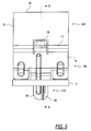
- the pair of spring fingers 29 are best illustrated in FIG. 6.
- the first leg 14 includes one of the pair of spring fingers 29 flexibly connected thereto, and projecting inwardly therefrom.
- the second leg 16 includes a second of the pair of spring fingers 29 flexibly connected thereto, and projecting inwardly therefrom.
- the spring fingers 29 are flexibly connected to the legs 14 and 16 such that when a transmission line is inserted into the hanger 10 the spring fingers 29 flex outward with respect to the legs 14 and 16, respectively, and force the transmission line against the top potion 30 of the partially cylindrical member 12.
- the spring fingers 29 provide spring resistance against the transmission line after it is inserted in the hanger 10.
- the spring fingers 29 also penetrate or bite into the jacket of the transmission line to further secure the transmission line within the hanger 10.
- the spring fingers 29 help minimize the longitudinal movement of the transmission line in the hanger 10. Longitudinal movement is defined as movement in a direction parallel to the length of the transmission line.
- the spring fingers 29 also help minimize transmission line vibration.
- the extended section 105 includes one spring finger 29 projecting inwardly from the extended section 105 and into the transmission line retention section 100.
- the first leg 14 may include one spring finger 29 flexibly connected thereto, and projecting inwardly therefrom.
- the one spring finger 29 is flexibly connected to the first leg 14 such that when a transmission line is inserted into the hanger 10 the spring finger 29 flexes outward with respect to the first leg 14 and forces the transmission line against the top left potion of the partially cylindrical member 12.
- the one spring finger 29 can provide spring resistance against the transmission line after it is inserted in the hanger 10.
- the one spring finger 29 also bites into the jacket of the transmission line to further secure the transmission line within the hanger 10.
- the one spring finger 29 helps minimize the longitudinal movement of the transmission line in the hanger 10.
- the one spring finger 29 also helps minimize transmission line vibration.
- the second leg 16 may include one spring finger 29 flexibly connected thereto, and projecting inwardly therefrom, that forces the transmission line against the top right potion of the partially cylindrical member 12.
- the extended section 105 in conjunction with the one spring finger 29, allows the hanger 10 to accommodate a large range of different transmission line diameters by having the compliance to expand for larger transmission lines.
- the extended section 105 and the one spring finger 29 also have the compliance to allow the hanger 10 to accommodate a large range of transmission line diameters while still allowing the attachment section 110 to be inserted into the supporting structure 5.
- the extended section 105 in conjunction with the pair of spring fingers 29, allows the hanger 10 to accommodate a large range of different transmission line diameters by having the compliance to expand for larger transmission lines.
- the extended section 105 and the spring fingers 29 also have the compliance to allow the hanger 10 to accommodate a large range of transmission line diameters while still allowing the attachment section 110 to be inserted into the supporting structure 5.
- the two opposing spring fingers 29 will provide spring resistance against the transmission line, which in turn will force the transmission line against the top potion 30 of the partially cylindrical member 12, and bite into the jacket of the transmission line.
- the hanger 10 may be installed easily and quickly on the transmission line by pulling apart the legs 14 and 16 and slipping the hanger 10 over the transmission line such that the partially cylindrical member 12 is disposed around the transmission line and the spring fingers 29 are forced against the transmission line thus pressing the transmission line against the top potion 30 of the partially cylindrical member 12.
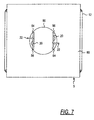
- the legs 14 and 16 are then pressed together to allow the locking barbs 22 to be inserted through the aperture 50, as illustrated in FIG. 7.
- the hanger 10 is inserted into the aperture 50 until the first sections 18 snap into contact with the supporting structure 5 at one or both of the pair of contact points 54 and 56 and the barb contact points 23 contact the inner surface 60 of the supporting structure 5, as illustrated in FIGS. 3a and 3b. This process is repeated for each hanger 10 that is installed along the length of the transmission line.
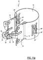
- FIGS. 5-9 illustrate different views of the hanger 10 installed in the supporting structure 5.
- the hanger 10 can also be readily uninstalled and reused in another location. To uninstall the hanger 10, the legs 14 and 16 are pressed together to allow the locking barbs 22 to be removed from the aperture 50. Next, the partially cylindrical member 12 is slipped off the transmission line by pulling apart the legs 14 and 16 and disengaging the spring fingers 29 from the transmission line jacket.
- the transmission line retention section 100 includes areas of resistance 25 for retaining the transmission line and accommodating a large range of transmission line diameters.
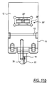
- FIGS. 10a, 10b, 11a, and 11b illustrate two embodiments of the areas of resistance 25.
- FIGS. 10a and 10b illustrate two opposing areas of resistance 25' that each include an inwardly curved portion 26' and an indentation 28'.
- the curved portion 26' is attached to the partially cylindrical member 12 at each end and provides spring resistance against the transmission line after it is inserted in the hanger 10.
- the indentations 28' help further secure the transmission line within the hanger 10 by penetrating or biting into the jacket of the transmission line. Thus, the indentations 28' minimize the longitudinal movement of the transmission line in the hanger 10 and also help minimize transmission line vibration.
- FIGS. 11a and 11b illustrate two opposing areas of resistance 25'' that each include an inwardly curved portion 26'' and a pair of tabs 28''.
- the curved portion 26'' is attached to the partially cylindrical member 12 at each end and provides spring resistance against the transmission line after it is inserted in the hanger 10.
- the inwardly bent tabs 28'' help further secure the transmission line within the hanger 10 by penetrating or biting into the jacket of the transmission line.
- the tabs 28'' minimizes the longitudinal movement of the transmission line in the hanger 10 and also help minimize transmission line vibration.
- the two opposing areas of resistance make the orientation of the transmission line inserted into the hanger 10 irrelevant. No matter how the transmission line is disposed in the hanger 10 (e.g ., the areas of resistance are in-between the corrugations of a corrugated cable or are in contact with one of the protruding corrugations), the two opposing areas of resistance 25 will provide spring resistance against the transmission line and the indentation 28' or tabs 28'' will penetrate into the jacket of the transmission line.
Landscapes
- Engineering & Computer Science (AREA)
- General Engineering & Computer Science (AREA)
- Architecture (AREA)
- Civil Engineering (AREA)
- Structural Engineering (AREA)
- Mechanical Engineering (AREA)
- Holders For Apparel And Elements Relating To Apparel (AREA)
- Roof Covering Using Slabs Or Stiff Sheets (AREA)
- Suspension Of Electric Lines Or Cables (AREA)
- Clamps And Clips (AREA)
- General Details Of Gearings (AREA)
Applications Claiming Priority (2)
| Application Number | Priority Date | Filing Date | Title |
|---|---|---|---|
| US229843 | 1999-01-12 | ||
| US09/229,843 US6161804A (en) | 1999-01-12 | 1999-01-12 | Transmission line hanger |
Publications (2)
| Publication Number | Publication Date |
|---|---|
| EP1020672A1 true EP1020672A1 (fr) | 2000-07-19 |
| EP1020672B1 EP1020672B1 (fr) | 2004-09-01 |
Family
ID=22862898
Family Applications (1)
| Application Number | Title | Priority Date | Filing Date |
|---|---|---|---|
| EP00100368A Expired - Lifetime EP1020672B1 (fr) | 1999-01-12 | 2000-01-07 | Collier de serrage d'une ligne de transmission |
Country Status (6)
| Country | Link |
|---|---|
| US (1) | US6161804A (fr) |
| EP (1) | EP1020672B1 (fr) |
| KR (1) | KR100445855B1 (fr) |
| CN (1) | CN1196882C (fr) |
| BR (1) | BR0000046A (fr) |
| DE (1) | DE60013333T2 (fr) |
Cited By (3)
| Publication number | Priority date | Publication date | Assignee | Title |
|---|---|---|---|---|
| US6899305B2 (en) | 1999-01-12 | 2005-05-31 | Andrew Corporation | Stackable transmission line hanger |
| US7090174B2 (en) | 2001-11-09 | 2006-08-15 | Andrew Corporation | Anchor rail adapter and hanger and method |
| WO2017079020A1 (fr) * | 2015-11-03 | 2017-05-11 | Commscope Technologies Llc | Dispositif de suspension destiné à des câbles de montage |
Families Citing this family (60)
| Publication number | Priority date | Publication date | Assignee | Title |
|---|---|---|---|---|
| US6161804A (en) * | 1999-01-12 | 2000-12-19 | Andrew Corporation | Transmission line hanger |
| US6354543B1 (en) * | 1999-01-12 | 2002-03-12 | Andrew Corporation | Stackable transmission line hanger |
| US6276644B1 (en) * | 2000-03-20 | 2001-08-21 | Gilbert M. Jennings | Compact cable anchor for retainment and attachment of cables and tubing |
| JP2001326027A (ja) * | 2000-05-15 | 2001-11-22 | Nec Gumma Ltd | Usbコネクタの抜け止め装置 |
| US6443402B1 (en) * | 2000-12-01 | 2002-09-03 | Commscope Properties, Llc | Cable hanger |
| USD461396S1 (en) | 2001-02-13 | 2002-08-13 | Commscope Properties, Llc | Cable hanger |
| US6622976B1 (en) | 2001-09-18 | 2003-09-23 | Daniel J. Ianello | Cable hanger for installing cables on transmitting tower |
| ATE328231T1 (de) * | 2001-10-11 | 2006-06-15 | Wesley Arbuckle | Befestigungselement |
| US7025309B2 (en) | 2002-11-04 | 2006-04-11 | Andrew Corporation | Line hanger |
| FR2852157B1 (fr) * | 2003-03-06 | 2005-05-27 | Dispositif de fixation d'un fil sur un element porteur muni d'au moins deux ouvertures et ensemble porteur pour chemin de cables comportant au moins un tel dispositif | |
| US7097142B1 (en) * | 2003-08-13 | 2006-08-29 | Beverly Manufacturing Company | One-piece resilient stackable hanger |
| US7175138B2 (en) * | 2004-05-10 | 2007-02-13 | Andrew Corporation | Stackable cable hanger |
| CA2513960A1 (fr) * | 2004-07-28 | 2006-01-28 | Greenlee Textron Inc. | Dispositif de gerbage de fils et de cables |
| TWI314034B (en) * | 2005-12-07 | 2009-08-21 | Amco Tec Internat Inc | Buckle ring structure |
| KR101345338B1 (ko) * | 2006-07-20 | 2013-12-27 | 삼성디스플레이 주식회사 | 액정표시장치 |
| KR20080073860A (ko) * | 2007-02-07 | 2008-08-12 | 엘지전자 주식회사 | 조리 기기용 히터 서포터 및 이를 이용한 조리 기기 |
| US7681843B2 (en) * | 2007-05-24 | 2010-03-23 | Cambridge Silversmiths Ltd., Inc. | Display and retaining clip |
| US20090113677A1 (en) * | 2007-11-02 | 2009-05-07 | Marketing Displays Inc. | Sliding Member Bollard Bracket |
| US8011621B2 (en) * | 2008-05-29 | 2011-09-06 | Andrew Llc | Snap-in cable hanger clip |
| IT1395161B1 (it) | 2009-08-12 | 2012-09-05 | Fi Mo Tec Spa | Collare di supporto per articoli lungiformi, in particolare cavi, tubi e/o simili |
| US9671046B2 (en) * | 2009-09-30 | 2017-06-06 | Thomas & Betts International Llc | Cable suspension assembly |
| US9206499B2 (en) * | 2010-08-30 | 2015-12-08 | United Technologies Corporation | Minimizing blockage of holes in turbine engine components |
| US8403712B2 (en) | 2010-11-10 | 2013-03-26 | Hubbell Incorporated | Barbed contact member for an electrical receptacle |
| WO2012129095A1 (fr) * | 2011-03-18 | 2012-09-27 | Image Industries | Attache d'acheminement empilable |
| CA2847083A1 (fr) | 2011-10-10 | 2013-04-18 | F. Hoffmann-La Roche Ag | Composes antiviraux |
| US8727288B2 (en) | 2012-04-03 | 2014-05-20 | Commscope, Inc. Of North Carolina | Snap-in bracket for attaching cabling to a support |
| BR102013001676B1 (pt) * | 2013-01-23 | 2021-08-10 | Electrolux Do Brasil S.A | Mancal de tração e articulação da haste do conjunto de prateleiras deslizantes |
| US9206925B2 (en) | 2013-03-14 | 2015-12-08 | Panduit Corp. | Gangable conduit hanger assembly |
| US20160121822A1 (en) * | 2013-05-29 | 2016-05-05 | International Engine Intellectual Property Company ,LLC. | Harness clip and system for clipping wiring harness |
| US9316029B2 (en) * | 2013-07-01 | 2016-04-19 | Kiekert Ag | C-shaped attachment element for vehicle lock |
| US9581782B2 (en) * | 2014-08-28 | 2017-02-28 | Hubbell Incorporated | Cable management spool mounting assembly |
| JP6477021B2 (ja) * | 2015-03-02 | 2019-03-06 | 住友電装株式会社 | 電線保護部材 |
| EP3742567B1 (fr) | 2015-03-27 | 2022-08-31 | CommScope Technologies LLC | Suspension pour câble |
| NL2015404B1 (en) * | 2015-09-07 | 2017-03-22 | Walraven Holding Bv J Van | Conduit clip. |
| CN105422995A (zh) * | 2015-12-14 | 2016-03-23 | 无锡市永亿精密铸造有限公司 | 一种石油管道支架 |
| US9791073B2 (en) * | 2015-12-15 | 2017-10-17 | Cooper Technologies Company | Pipe clamp |
| US9879803B2 (en) * | 2016-01-14 | 2018-01-30 | Maxdao Limited | Connectable cable organizer |
| GB201603692D0 (en) * | 2016-03-03 | 2016-04-20 | Linian Supply Co Ltd | Fixing apparatus and method |
| CN115275914A (zh) | 2016-08-15 | 2022-11-01 | 康普技术有限责任公司 | 用于安装线缆的悬挂器 |
| EP3539191A4 (fr) * | 2016-11-11 | 2020-07-01 | Commscope Technologies LLC | Adaptateur pour le montage de câbles et de porte-câbles |
| WO2018136210A1 (fr) * | 2017-01-19 | 2018-07-26 | Commscope Technologies Llc | Dispositif de suspension servant au montage de multiples câbles |
| CN108569227A (zh) * | 2017-03-13 | 2018-09-25 | 标致雪铁龙集团 | 一种用于管线路的固定装置及汽车 |
| DE102017108335B4 (de) * | 2017-04-19 | 2019-01-03 | Rittal Gmbh & Co. Kg | Befestigungsanordnung und ein entsprechendes Schaltschrankgehäuse |
| GB201713754D0 (en) * | 2017-08-28 | 2017-10-11 | Linian Supply Co Ltd | Fixing apparatus and method |
| CN108050305A (zh) * | 2017-11-30 | 2018-05-18 | 博耐尔汽车电气系统有限公司 | 一种汽车空调管路的减震垫圈 |
| DE202017107545U1 (de) * | 2017-12-12 | 2019-03-18 | A. Raymond Et Cie Scs | Montageklammer |
| WO2020146531A1 (fr) | 2019-01-09 | 2020-07-16 | Hubbell Incorporated | Attache-câbles pour la gestion de fils |
| WO2021007014A1 (fr) * | 2019-07-09 | 2021-01-14 | Commscope Technologies Llc | Enveloppe pour suspensions de câble |
| GB2592263B (en) | 2020-02-24 | 2024-06-12 | Linian Lab Ltd | Fastening device |
| GB202016972D0 (en) * | 2020-10-26 | 2020-12-09 | Linian Lab Ltd | Optical fibre clip |
| US12249822B2 (en) | 2022-06-24 | 2025-03-11 | Hubbell Incorporated | Electrical cable hangers |
| USD1008006S1 (en) | 2022-06-24 | 2023-12-19 | Hubbell Incorporated | Cable hanger |
| USD1008007S1 (en) | 2022-06-24 | 2023-12-19 | Hubbell Incorporated | Cable hanger |
| USD1007285S1 (en) | 2022-06-24 | 2023-12-12 | Hubbell Incorporated | Cable hanger |
| USD1007284S1 (en) | 2022-06-24 | 2023-12-12 | Hubbell Incorporated | Cable hanger |
| USD1008004S1 (en) | 2022-06-24 | 2023-12-19 | Hubbell Incorporated | Cable hanger |
| USD1007286S1 (en) | 2022-06-24 | 2023-12-12 | Hubbell Incorporated | Cable hanger |
| USD1067761S1 (en) | 2022-08-22 | 2025-03-25 | Hubbell Incorporated | Electrical component hanger |
| USD1061228S1 (en) | 2022-08-22 | 2025-02-11 | Hubbell Incorporated | Electrical component hanger |
| USD1017388S1 (en) | 2022-10-01 | 2024-03-12 | Hubbell Incorporated | Cable hanger |
Citations (4)
| Publication number | Priority date | Publication date | Assignee | Title |
|---|---|---|---|---|
| US2981513A (en) * | 1958-05-02 | 1961-04-25 | Dwight L Brown | Tube supporting clip |
| FR2417870A1 (fr) * | 1978-02-20 | 1979-09-14 | Raymond A Ste | Agrafe de gaines a diametre variable |
| FR2483541A1 (fr) * | 1980-05-28 | 1981-12-04 | Sonofam | Agrafe pour la fixation de gaines de diametres multiples sur des supports tels que des toles perforees |
| EP0183394A2 (fr) * | 1984-11-26 | 1986-06-04 | Andrew A.G. | Collier de fixation de guide d'ondes |
Family Cites Families (38)
| Publication number | Priority date | Publication date | Assignee | Title |
|---|---|---|---|---|
| US396677A (en) * | 1889-01-22 | Device for fastening conductors | ||
| US2065843A (en) * | 1932-09-12 | 1936-12-29 | John H Van Uum | Securing device for cables or the like |
| DE710034C (de) * | 1935-10-19 | 1941-09-02 | Otto Dehne | Federnde Schellen zum Befestigen von Rohren, elektrischen Leitungen u. dgl. an Waenden |
| US2417870A (en) * | 1943-05-10 | 1947-03-25 | Gen Motors Corp | Propeller control |
| US2397680A (en) * | 1944-05-08 | 1946-04-02 | Adel Prec Products Corp | Snap on clip |
| US2453980A (en) * | 1946-10-28 | 1948-11-16 | Tinnerman Products Inc | Fastening device for cables, wires, or the like |
| US2483541A (en) * | 1948-04-30 | 1949-10-04 | American Steel & Wire Co | Stop device for knitting machines |
| US2716703A (en) * | 1952-05-15 | 1955-08-30 | James M Kane | Television antenna |
| US2682385A (en) * | 1953-03-02 | 1954-06-29 | Newell Mfg Co | Curtain rod bracket |
| US2941768A (en) * | 1958-09-22 | 1960-06-21 | Robert L Brown | Tubing fastener |
| US3154281A (en) * | 1962-02-20 | 1964-10-27 | Frank Charles | Holder for electronic components |
| US3131447A (en) * | 1962-05-31 | 1964-05-05 | George A Tinnerman | Mounting clamps |
| GB1062633A (en) * | 1963-03-07 | 1967-03-22 | Wilmot Breeden Ltd | Improvements in or relating to pipe mountings |
| US3237905A (en) * | 1963-11-12 | 1966-03-01 | Mallory & Co Inc P R | Vertical mounting clamp for cardboard tubular capacitors |
| US3346863A (en) * | 1964-12-17 | 1967-10-10 | Gen Electric | Television antenna and connector apparatus |
| GB1108004A (en) * | 1965-10-22 | 1968-03-27 | Itw Ltd | Clips for mounting rods and similar elongated members on panels |
| US3444596A (en) * | 1968-01-31 | 1969-05-20 | Illinois Tool Works | Pipe clip |
| US3501117A (en) * | 1968-05-31 | 1970-03-17 | Illinois Tool Works | Clip device |
| DE6912883U (de) * | 1969-03-29 | 1969-10-02 | Kabel Metallwerke Ghh | Vorrichtung zum zugentlasteten einfuehren einer elektrischen leitung in ein festes gehaeuse |
| US3822411A (en) * | 1971-05-06 | 1974-07-02 | Andrew Corp | Corrugated waveguide construction |
| JPS504171U (fr) * | 1973-05-12 | 1975-01-17 | ||
| US4047133A (en) * | 1973-09-17 | 1977-09-06 | Andrew Corporation | Continuous corrugated waveguide and method of producing the same |
| US4334659A (en) * | 1980-07-11 | 1982-06-15 | Nifco Inc. | Plastic retaining-fastening device |
| JPS5780123U (fr) * | 1980-11-05 | 1982-05-18 | ||
| DK149100C (da) * | 1982-01-15 | 1986-06-16 | Jon Holk | Kassette og tilhoerende apparat med en skaerm til periodisk visning af et antal billeder |
| DE3300779C2 (de) * | 1983-01-12 | 1984-12-06 | Fa. A. Raymond, 7850 Lörrach | Kabelschelle für variable Durchmesser |
| JPS59219508A (ja) * | 1983-05-27 | 1984-12-10 | 日産自動車株式会社 | ハ−ネスクリツプ |
| US4763132A (en) * | 1984-11-26 | 1988-08-09 | Andrew Corporation | Resilient one piece waveguide hanger interlockable with antenna tower |
| US4654612A (en) * | 1984-12-18 | 1987-03-31 | Andrew Corporation | Spring hanger system for UHF circular waveguide having glide ring and clamping ring connected by constant force springs |
| US4813639A (en) * | 1987-10-01 | 1989-03-21 | Andrew Corporation | Cluster mounting system for supporting coaxial cables and the like |
| US4958792A (en) * | 1989-05-09 | 1990-09-25 | B-Line Systems, Inc. | Clip for supporting conduit and the like |
| JPH053408A (ja) * | 1991-10-28 | 1993-01-08 | Dx Antenna Co Ltd | アンテナポ−ル取付具の製造方法 |
| US5167533A (en) * | 1992-01-08 | 1992-12-01 | Andrew Corporation | Connector for coaxial cable having hollow inner conductors |
| US5334051A (en) * | 1993-06-17 | 1994-08-02 | Andrew Corporation | Connector for coaxial cable having corrugated outer conductor and method of attachment |
| US5393021A (en) * | 1994-03-07 | 1995-02-28 | Cablewave Systems | Cable hanger |
| US5967468A (en) * | 1998-01-26 | 1999-10-19 | Tennaplex Systems, Inc. | Cable retaining clamp |
| US6161804A (en) * | 1999-01-12 | 2000-12-19 | Andrew Corporation | Transmission line hanger |
| KR200300083Y1 (ko) * | 1999-04-30 | 2003-01-14 | 김영산 | 전선배관용 파이프행거 |
-
1999
- 1999-01-12 US US09/229,843 patent/US6161804A/en not_active Expired - Lifetime
-
2000
- 2000-01-07 DE DE60013333T patent/DE60013333T2/de not_active Expired - Lifetime
- 2000-01-07 EP EP00100368A patent/EP1020672B1/fr not_active Expired - Lifetime
- 2000-01-07 KR KR10-2000-0000615A patent/KR100445855B1/ko not_active Expired - Fee Related
- 2000-01-12 CN CNB001010735A patent/CN1196882C/zh not_active Expired - Lifetime
- 2000-01-12 BR BR0000046-9A patent/BR0000046A/pt not_active IP Right Cessation
Patent Citations (4)
| Publication number | Priority date | Publication date | Assignee | Title |
|---|---|---|---|---|
| US2981513A (en) * | 1958-05-02 | 1961-04-25 | Dwight L Brown | Tube supporting clip |
| FR2417870A1 (fr) * | 1978-02-20 | 1979-09-14 | Raymond A Ste | Agrafe de gaines a diametre variable |
| FR2483541A1 (fr) * | 1980-05-28 | 1981-12-04 | Sonofam | Agrafe pour la fixation de gaines de diametres multiples sur des supports tels que des toles perforees |
| EP0183394A2 (fr) * | 1984-11-26 | 1986-06-04 | Andrew A.G. | Collier de fixation de guide d'ondes |
Cited By (5)
| Publication number | Priority date | Publication date | Assignee | Title |
|---|---|---|---|---|
| US6899305B2 (en) | 1999-01-12 | 2005-05-31 | Andrew Corporation | Stackable transmission line hanger |
| US7090174B2 (en) | 2001-11-09 | 2006-08-15 | Andrew Corporation | Anchor rail adapter and hanger and method |
| WO2017079020A1 (fr) * | 2015-11-03 | 2017-05-11 | Commscope Technologies Llc | Dispositif de suspension destiné à des câbles de montage |
| US9903510B2 (en) | 2015-11-03 | 2018-02-27 | Commscope Technologies Llc | Hanger for mounting cables |
| US9995414B2 (en) | 2015-11-03 | 2018-06-12 | Commscope Technologies Llc | Hanger for mounting cables |
Also Published As
| Publication number | Publication date |
|---|---|
| EP1020672B1 (fr) | 2004-09-01 |
| KR20000053416A (ko) | 2000-08-25 |
| CN1196882C (zh) | 2005-04-13 |
| KR100445855B1 (ko) | 2004-08-30 |
| DE60013333T2 (de) | 2005-02-17 |
| BR0000046A (pt) | 2000-08-29 |
| US6161804A (en) | 2000-12-19 |
| DE60013333D1 (de) | 2004-10-07 |
| CN1260605A (zh) | 2000-07-19 |
Similar Documents
| Publication | Publication Date | Title |
|---|---|---|
| US6161804A (en) | Transmission line hanger | |
| EP1096594B1 (fr) | Collier de serrage empilable d'une ligne de transmission | |
| US6899305B2 (en) | Stackable transmission line hanger | |
| US7090174B2 (en) | Anchor rail adapter and hanger and method | |
| CA2084559C (fr) | Suspente pour tuyauterie adaptee au brasage | |
| US7097142B1 (en) | One-piece resilient stackable hanger | |
| US5405111A (en) | Bracket for anchoring apparatus between wall studs | |
| US5639049A (en) | Compact cable clip for retainment of cables and tubing | |
| CA2134048C (fr) | Pince a cable | |
| US20040113027A1 (en) | Fastener for pipe or the like | |
| CA2097040C (fr) | Etrier de suspension clipsale, pour tubes | |
| WO2007070271A1 (fr) | Fixation pour objets circulaires | |
| CN102113180A (zh) | 用于安装监视摄像机的装置 | |
| US7549613B1 (en) | Tube clamp for an angle bracket | |
| US6477770B1 (en) | Cable supporting methods | |
| EP0547128B1 (fr) | Systemes de tablettes de cables et dispositifs d'assemblage pour ces systemes | |
| JPS61180007A (ja) | ハンガ− | |
| CN212131546U (zh) | U形束带、开槽结构构件组件和支杆接纳件组件 | |
| EP0599634B1 (fr) | Dispositif de couplage pour composants de support de câble | |
| JP6450984B1 (ja) | 固定具 | |
| KR20000008549U (ko) | 원터치 파이프 클램프 | |
| EP1097784A1 (fr) | Outil de montage des écrous encagés et procédé pour sa mise en oeuvre | |
| RU215011U1 (ru) | Хомут для крепления кабеля | |
| JPH06185505A (ja) | アースクランプ | |
| KR20050095291A (ko) | 관 이음 장치 |
Legal Events
| Date | Code | Title | Description |
|---|---|---|---|
| PUAI | Public reference made under article 153(3) epc to a published international application that has entered the european phase |
Free format text: ORIGINAL CODE: 0009012 |
|
| AK | Designated contracting states |
Kind code of ref document: A1 Designated state(s): DE FI FR GB SE |
|
| AX | Request for extension of the european patent |
Free format text: AL;LT;LV;MK;RO;SI |
|
| 17P | Request for examination filed |
Effective date: 20000620 |
|
| AKX | Designation fees paid |
Free format text: DE FI FR GB SE |
|
| 17Q | First examination report despatched |
Effective date: 20020423 |
|
| GRAP | Despatch of communication of intention to grant a patent |
Free format text: ORIGINAL CODE: EPIDOSNIGR1 |
|
| GRAS | Grant fee paid |
Free format text: ORIGINAL CODE: EPIDOSNIGR3 |
|
| GRAA | (expected) grant |
Free format text: ORIGINAL CODE: 0009210 |
|
| AK | Designated contracting states |
Kind code of ref document: B1 Designated state(s): DE FI FR GB SE |
|
| REG | Reference to a national code |
Ref country code: GB Ref legal event code: FG4D |
|
| REF | Corresponds to: |
Ref document number: 60013333 Country of ref document: DE Date of ref document: 20041007 Kind code of ref document: P |
|
| REG | Reference to a national code |
Ref country code: SE Ref legal event code: TRGR |
|
| ET | Fr: translation filed | ||
| PLBE | No opposition filed within time limit |
Free format text: ORIGINAL CODE: 0009261 |
|
| STAA | Information on the status of an ep patent application or granted ep patent |
Free format text: STATUS: NO OPPOSITION FILED WITHIN TIME LIMIT |
|
| 26N | No opposition filed |
Effective date: 20050602 |
|
| PGFP | Annual fee paid to national office [announced via postgrant information from national office to epo] |
Ref country code: DE Payment date: 20120127 Year of fee payment: 13 |
|
| PGFP | Annual fee paid to national office [announced via postgrant information from national office to epo] |
Ref country code: GB Payment date: 20120126 Year of fee payment: 13 Ref country code: SE Payment date: 20120127 Year of fee payment: 13 |
|
| REG | Reference to a national code |
Ref country code: SE Ref legal event code: EUG |
|
| GBPC | Gb: european patent ceased through non-payment of renewal fee |
Effective date: 20130107 |
|
| PG25 | Lapsed in a contracting state [announced via postgrant information from national office to epo] |
Ref country code: DE Free format text: LAPSE BECAUSE OF NON-PAYMENT OF DUE FEES Effective date: 20130801 Ref country code: SE Free format text: LAPSE BECAUSE OF NON-PAYMENT OF DUE FEES Effective date: 20130108 |
|
| REG | Reference to a national code |
Ref country code: DE Ref legal event code: R119 Ref document number: 60013333 Country of ref document: DE Effective date: 20130801 |
|
| PG25 | Lapsed in a contracting state [announced via postgrant information from national office to epo] |
Ref country code: GB Free format text: LAPSE BECAUSE OF NON-PAYMENT OF DUE FEES Effective date: 20130107 |
|
| REG | Reference to a national code |
Ref country code: FR Ref legal event code: PLFP Year of fee payment: 17 |
|
| PGFP | Annual fee paid to national office [announced via postgrant information from national office to epo] |
Ref country code: FI Payment date: 20160127 Year of fee payment: 17 |
|
| REG | Reference to a national code |
Ref country code: FR Ref legal event code: PLFP Year of fee payment: 18 |
|
| PG25 | Lapsed in a contracting state [announced via postgrant information from national office to epo] |
Ref country code: FI Free format text: LAPSE BECAUSE OF NON-PAYMENT OF DUE FEES Effective date: 20170107 |
|
| REG | Reference to a national code |
Ref country code: FR Ref legal event code: PLFP Year of fee payment: 19 |
|
| PGFP | Annual fee paid to national office [announced via postgrant information from national office to epo] |
Ref country code: FR Payment date: 20190125 Year of fee payment: 20 |