EP1020712B1 - Debitmetre massique de type coriolis et procede de fabrication correspondant - Google Patents
Debitmetre massique de type coriolis et procede de fabrication correspondant Download PDFInfo
- Publication number
- EP1020712B1 EP1020712B1 EP99926958A EP99926958A EP1020712B1 EP 1020712 B1 EP1020712 B1 EP 1020712B1 EP 99926958 A EP99926958 A EP 99926958A EP 99926958 A EP99926958 A EP 99926958A EP 1020712 B1 EP1020712 B1 EP 1020712B1
- Authority
- EP
- European Patent Office
- Prior art keywords
- conduit
- connecting portion
- flow tubes
- inlet
- mass flowmeter
- Prior art date
- Legal status (The legal status is an assumption and is not a legal conclusion. Google has not performed a legal analysis and makes no representation as to the accuracy of the status listed.)
- Expired - Lifetime
Links
- 238000004519 manufacturing process Methods 0.000 title claims description 4
- 239000012530 fluid Substances 0.000 claims abstract description 21
- 238000010276 construction Methods 0.000 claims abstract description 20
- 238000005452 bending Methods 0.000 claims abstract description 12
- 238000000034 method Methods 0.000 claims 1
- 238000005259 measurement Methods 0.000 abstract description 3
- 239000000463 material Substances 0.000 description 7
- 239000007788 liquid Substances 0.000 description 5
- 238000005219 brazing Methods 0.000 description 4
- 238000003466 welding Methods 0.000 description 4
- RYGMFSIKBFXOCR-UHFFFAOYSA-N Copper Chemical compound [Cu] RYGMFSIKBFXOCR-UHFFFAOYSA-N 0.000 description 3
- 239000004809 Teflon Substances 0.000 description 3
- 229920006362 Teflon® Polymers 0.000 description 3
- 230000000694 effects Effects 0.000 description 3
- 238000011010 flushing procedure Methods 0.000 description 3
- 238000009434 installation Methods 0.000 description 3
- 239000011889 copper foil Substances 0.000 description 2
- 230000035945 sensitivity Effects 0.000 description 2
- 229910001069 Ti alloy Inorganic materials 0.000 description 1
- 230000015572 biosynthetic process Effects 0.000 description 1
- 239000010949 copper Substances 0.000 description 1
- 229910052802 copper Inorganic materials 0.000 description 1
- 238000005260 corrosion Methods 0.000 description 1
- 230000007797 corrosion Effects 0.000 description 1
- 238000001514 detection method Methods 0.000 description 1
- 238000006073 displacement reaction Methods 0.000 description 1
- 235000013305 food Nutrition 0.000 description 1
- 229910000856 hastalloy Inorganic materials 0.000 description 1
- 239000012535 impurity Substances 0.000 description 1
- 230000035515 penetration Effects 0.000 description 1
- 229920001721 polyimide Polymers 0.000 description 1
- 230000004043 responsiveness Effects 0.000 description 1
- 239000010935 stainless steel Substances 0.000 description 1
- 229910001220 stainless steel Inorganic materials 0.000 description 1
Images

Classifications
-
- G—PHYSICS
- G01—MEASURING; TESTING
- G01F—MEASURING VOLUME, VOLUME FLOW, MASS FLOW OR LIQUID LEVEL; METERING BY VOLUME
- G01F1/00—Measuring the volume flow or mass flow of fluid or fluent solid material wherein the fluid passes through a meter in a continuous flow
- G01F1/76—Devices for measuring mass flow of a fluid or a fluent solid material
- G01F1/78—Direct mass flowmeters
- G01F1/80—Direct mass flowmeters operating by measuring pressure, force, momentum, or frequency of a fluid flow to which a rotational movement has been imparted
- G01F1/84—Coriolis or gyroscopic mass flowmeters
-
- G—PHYSICS
- G01—MEASURING; TESTING
- G01F—MEASURING VOLUME, VOLUME FLOW, MASS FLOW OR LIQUID LEVEL; METERING BY VOLUME
- G01F1/00—Measuring the volume flow or mass flow of fluid or fluent solid material wherein the fluid passes through a meter in a continuous flow
- G01F1/76—Devices for measuring mass flow of a fluid or a fluent solid material
- G01F1/78—Direct mass flowmeters
- G01F1/80—Direct mass flowmeters operating by measuring pressure, force, momentum, or frequency of a fluid flow to which a rotational movement has been imparted
- G01F1/84—Coriolis or gyroscopic mass flowmeters
- G01F1/8409—Coriolis or gyroscopic mass flowmeters constructional details
-
- G—PHYSICS
- G01—MEASURING; TESTING
- G01F—MEASURING VOLUME, VOLUME FLOW, MASS FLOW OR LIQUID LEVEL; METERING BY VOLUME
- G01F1/00—Measuring the volume flow or mass flow of fluid or fluent solid material wherein the fluid passes through a meter in a continuous flow
- G01F1/76—Devices for measuring mass flow of a fluid or a fluent solid material
- G01F1/78—Direct mass flowmeters
- G01F1/80—Direct mass flowmeters operating by measuring pressure, force, momentum, or frequency of a fluid flow to which a rotational movement has been imparted
- G01F1/84—Coriolis or gyroscopic mass flowmeters
- G01F1/8409—Coriolis or gyroscopic mass flowmeters constructional details
- G01F1/8413—Coriolis or gyroscopic mass flowmeters constructional details means for influencing the flowmeter's motional or vibrational behaviour, e.g., conduit support or fixing means, or conduit attachments
-
- G—PHYSICS
- G01—MEASURING; TESTING
- G01F—MEASURING VOLUME, VOLUME FLOW, MASS FLOW OR LIQUID LEVEL; METERING BY VOLUME
- G01F1/00—Measuring the volume flow or mass flow of fluid or fluent solid material wherein the fluid passes through a meter in a continuous flow
- G01F1/76—Devices for measuring mass flow of a fluid or a fluent solid material
- G01F1/78—Direct mass flowmeters
- G01F1/80—Direct mass flowmeters operating by measuring pressure, force, momentum, or frequency of a fluid flow to which a rotational movement has been imparted
- G01F1/84—Coriolis or gyroscopic mass flowmeters
- G01F1/845—Coriolis or gyroscopic mass flowmeters arrangements of measuring means, e.g., of measuring conduits
- G01F1/8468—Coriolis or gyroscopic mass flowmeters arrangements of measuring means, e.g., of measuring conduits vibrating measuring conduits
- G01F1/8472—Coriolis or gyroscopic mass flowmeters arrangements of measuring means, e.g., of measuring conduits vibrating measuring conduits having curved measuring conduits, i.e. whereby the measuring conduits' curved center line lies within a plane
- G01F1/8477—Coriolis or gyroscopic mass flowmeters arrangements of measuring means, e.g., of measuring conduits vibrating measuring conduits having curved measuring conduits, i.e. whereby the measuring conduits' curved center line lies within a plane with multiple measuring conduits
-
- G—PHYSICS
- G01—MEASURING; TESTING
- G01F—MEASURING VOLUME, VOLUME FLOW, MASS FLOW OR LIQUID LEVEL; METERING BY VOLUME
- G01F1/00—Measuring the volume flow or mass flow of fluid or fluent solid material wherein the fluid passes through a meter in a continuous flow
- G01F1/76—Devices for measuring mass flow of a fluid or a fluent solid material
- G01F1/78—Direct mass flowmeters
- G01F1/80—Direct mass flowmeters operating by measuring pressure, force, momentum, or frequency of a fluid flow to which a rotational movement has been imparted
- G01F1/84—Coriolis or gyroscopic mass flowmeters
- G01F1/845—Coriolis or gyroscopic mass flowmeters arrangements of measuring means, e.g., of measuring conduits
- G01F1/8468—Coriolis or gyroscopic mass flowmeters arrangements of measuring means, e.g., of measuring conduits vibrating measuring conduits
- G01F1/8481—Coriolis or gyroscopic mass flowmeters arrangements of measuring means, e.g., of measuring conduits vibrating measuring conduits having loop-shaped measuring conduits, e.g. the measuring conduits form a loop with a crossing point
- G01F1/8486—Coriolis or gyroscopic mass flowmeters arrangements of measuring means, e.g., of measuring conduits vibrating measuring conduits having loop-shaped measuring conduits, e.g. the measuring conduits form a loop with a crossing point with multiple measuring conduits
-
- Y—GENERAL TAGGING OF NEW TECHNOLOGICAL DEVELOPMENTS; GENERAL TAGGING OF CROSS-SECTIONAL TECHNOLOGIES SPANNING OVER SEVERAL SECTIONS OF THE IPC; TECHNICAL SUBJECTS COVERED BY FORMER USPC CROSS-REFERENCE ART COLLECTIONS [XRACs] AND DIGESTS
- Y10—TECHNICAL SUBJECTS COVERED BY FORMER USPC
- Y10T—TECHNICAL SUBJECTS COVERED BY FORMER US CLASSIFICATION
- Y10T29/00—Metal working
- Y10T29/49—Method of mechanical manufacture
Definitions
- the present invention relates to a Coriolis mass flowmeter and, more particularly, to a loop-type Coriolis mass flowmeter in which two parallel bent tubes are connected in series.
- Coriolis forces acting on the tube are proportional to a mass flow rate.
- a mass flowmeter based on this principle (a Coriolis mass flowmeter) is well known.
- Flow tubes used in this Coriolis mass flowmeter are broadly classified into bent tubes and straight tubes according to their shape.
- a mass flow rate is measured as a difference in the displacement of the straight tube caused by the Coriolis forces between the supporting point and the middle portion of the straight tube, i.e., a phase difference signal, when the Coriolis mass flowmeter is vibrated in a direction vertical to the axis of the straight tube supported at both ends.
- a phase difference signal i.e., a phase difference signal
- Coriolis mass flowmeters of the bent tube type in which the shape of the bent tube can be selected appropriately to effectively take out Coriolis forces, can detect mass flow rates with high sensitivity. It is also known that in order to more efficiently drive this measuring bent tube, the bent tube in which a fluid to be measured flows is constituted of two parallel tubes.
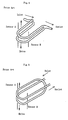
- FIG. 4 schematically shows this conventional Coriolis mass flowmeter of the two parallel bent tube type.
- the flow tube is fabricated from two parallel U-shaped tubes in which a branching portion is formed on the inlet side of the fluid to be measured and a junction portion is formed on the outlet side thereof.
- the fluid to be measured is equally divided into two flow tubes on the inlet side and joins on the outlet side of the flow tubes.
- Pressure losses or clogging of flow tubes with the fluid to be measured may sometimes occur in the branching portion at the inlet of the fluid and the junction portion at the outlet thereof. This poses a problem especially in the case of high-viscosity fluids and liquids such as perishable and easy-to-clog foods. Furthermore, when one flow tube is recovered from clogging during the flushing of flow tubes with a branching portion, the flushing performance of the other flow tube deteriorates, leading to a long flushing time.
- a loop-type Coriolis mass flowmeter in which two practically parallel bent tubes are fabricated from one bent tube as shown in FIG. 5 and thereby the fluid to be measured is caused to flow in series, is also known as an improvement on the above Coriolis mass flowmeter.
- tubes of this loop type In tubes of this loop type, however, the problem resulting from the formation of the above branching and junction portions can be solved, but their connection to external piping is complex and difficult because of their three-dimensional (not two-dimensional) geometry. At the same time, measuring accuracy is affected by strains caused during the fabrication of flow tubes, and the tubes of the loop type are susceptible to the effect of external vibrations.
- An example of a loop type Coriolis mass flowmeter is disclosed in WO 89/01134 A .
- an object of the present invention is to provide a Coriolis mass flowmeter which has a simple connection to external piping and can be assembled in a simplified manner while maintaining the advantage of the Coriolis mass flowmeter having a parallel double bent tube, that is, freedom of pressure losses or clogging with a fluid by bending a single tube in the above-mentioned manner to eliminate branching and junction portions.
- Another object of the present invention is to provide a Coriolis mass flowmeter which can measure mass flow rate with high accuracy by reducing strains caused during working and at the same time by reducing the vibrations of external piping, etc.
- the Coriolis mass flowmeter according to the present invention is a type in which a fluid to be measured is caused to flow in flow tubes connected in series by forming two parallel flow tubes 1 and 2, which are obtained by bending a single tube.
- the Coriolis mass flowmeter is characterized in that the inlet portion of conduit between an external connecting portion 35 connected to inlet piping and an inlet of one flow tube 2 is bent in an L shape and further bent in another direction, and the outlet portion of conduit between an external connecting portion 36 connected to outlet piping and an outlet of the other flow tube 1 bent in an L shape symmetrically with respect to the inlet portion of conduit, with an additional bend in another direction combined, with the result that the external connecting portions 35 and 36 are arranged on the same axis. This facilitates horizontal external connection during assembly.
- loop-type bent tubes need to be three-dimensionally bent.
- this three-dimensional bending can be accomplished with the connecting portions of the inlet portion of conduit, outlet portion of conduit and two flow tubes.
- flow tubes that require working without generation of strains can be formed by two-dimensional bending alone.
- a fixing member 32 of hollow construction is provided to integrally fix each end of the two flow tubes 1 and 2 via a supporting member 33 fabricated from a separate sheet and there is also provided an outer casing 30 which further supports this fixing member 32.
- the supporting member 33 is fixedly fitted to the fixing member at two locations opposite to the hollow fixing member 32 for each end of each of the flow tubes 1 and 2 and, at the same time, fixes the ends of the flow tubes 1 and 2. This facilitates the installation and fixing of the flow tubes and can prevent unwanted torque, vibration and wobble of the flow tubes.
- firm supporting is achieved at low cost with the use of supporting members fabricated from sheets and a hollow fixing member for fixing the supporting members, thereby reducing the vibrations of external piping, etc. and permitting a high-accuracy measurement of mass flow rate.
- the outer casing 30 has a hollow shell construction and the fixing member 32 is supported by the outer casing at a plurality of points (supporting portions 38) independently, not over the whole surface. Furthermore, a pressure-resistant case 31 is provided to be tightly connected to the outer casing 30. This pressure-resistant case 31 accommodates one conduit including the flow tubes and all accessory components of the conduit that include a drive 15, a pair of detecting sensors 16 and 17 and the fixing member 32.
- the outer casing has a shell construction and the pressure-resistant case is connected integrally to the outer casing. This not only enables the vibrating structural portions of flow tubes to be strongly protected against stresses from external piping, but also prevents the liquid flowing through the tubes from flowing out of the pressure-resistant vessel even in case of a breakage of the tubes.
- the method of making the Coriolis mass flowmeter involves integrally assembling the conduit and accessory components of the conduit, such as the fixing member 32 for fixing each end of the flow tubes, the drive 15 and the pair of detecting sensors 16 and 17, as a unit.
- This unit is arranged in the outer casing 30 having a shell construction in a manner that the outer connecting portions 35 and 36 are on the same axis. This facilitates assembling and can reduce the assembling time.
- FIGS. 1 to 3 show an example of Coriolis mass flowmeter to which the present invention is applied.
- the following explanation will be made by supposing a case where flow tubes of the two parallel bent tube type fabricated by bending one tube are installed in a vertical plane. However, it is also possible to install the flow tubes in a horizontal plane.
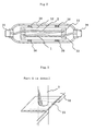
- FIG. 1 is a front view of the flow tubes.
- FIG. 2 is a view partly in section of the Coriolis mass flowmeter installed in a vertical plane as viewed from the top (the top of FIG. 1 ) in order to show the construction of the flow tubes in particular. In FIG. 2 , the drive, detecting sensors, etc. are not shown.
- FIG. 3 is a detail of Part A of FIG. 1 .
- the flow tubes 1 and 2 of the Coriolis mass flowmeter are bent tubes curved in a portal shape and both the tubes have the same shape. These flow tubes are fabricated from one continuous conduit. As mentioned above, flow tubes are portions of tube driven for resonance to produce Coriolis forces and they are expressed by flow tube 1 and flow tube 2. The whole of the flow tubes, including connecting portions which connect these two flow tubes together, and an inlet portion and an outlet portion connected to outer piping, is fabricated from one conduit.
- This Coriolis mass flowmeter is horizontally symmetric and permits a liquid to flow in and out from either side. However, the following description is based on the assumption that in the Coriolis mass flowmeter shown, a fluid to be measured flows in from the left side of FIG. 1 ( FIG. 2 ) and flows out to the right side of the figure.
- a liquid to be measured flows horizontally into an inlet portion of conduit after passing through an external connecting portion 35 from external inlet piping.
- the inlet portion of conduit is bent upward in the shape of the letter L as shown in FIG. 1 and is also bent in a different direction as shown in FIG. 2 .
- the liquid to be measured passes through a flow tube 2 from this inlet portion of conduit, enters a flow tube 1 after passing through the connecting portion of conduit from the bottom on the right side of FIG. 1 , and further passes through the outlet portion of conduit from the flow tube 1, finally flowing out into external outlet piping from an external connecting portion 36.
- the outlet portion of conduit is bent and fabricated symmetrically with respect to the inlet portion of conduit.
- the conduit is thus formed in a loop shape and bent in an L shape to the external connecting portions 35 and 36 to inlet piping/outlet piping in the directions opposite to each other. At the same time, bending in a different direction is performed and the external connecting portions to inlet piping and outlet piping are arranged on the same axis, thus facilitating external horizontal connection during assembling.
- the flow tubes 1 and 2 are provided with a drive 15 and a pair of detecting sensors 16 and 17, which will be described later in detail, and the drive and detecting sensors are wired. Near both ends of the flow tubes 1 and 2 are provided bases plates 26 and 27 for forming the nodes of vibrations when the flow tubes 1 and 2 are driven like a tuning fork. These bases plates 26 and 27 are secured to each other so that the flow tubes 1 and 2 are kept parallel.
- a supporting member 33 for fixing each end of the flow tubes 1 and 2 is fabricated from a sheet as seen in FIG. 3 , which shows a detail of Part A of FIG. 1 .
- the inlet portion and outlet portion are fixed by means of different supporting members 33 for each flow tube.
- the installation and fixing of the flow tubes are made easy by using different supporting members 33.
- thermal energy can be reduced to a minimum necessary amount in vacuum-brazing the flow tubes to the supporting members 33 by using members of small thermal capacity.
- This supporting member 33 is connected to the fixing member 32 of hollow construction in at least two upper and lower places.
- the illustrated fixing member 32 which is formed as a hollow member having an almost rectangular shape in cross section, fixes one end of the flow tube with both of the upper and lower sides of the rectangle, respectively.
- each end of one flow tube is supported in two places on the two sides of the hollow rectangle, and other two sides forming the sides of the fixing member 32 of hollow rectangle are fixed to an outer casing 30 as will be described later.
- a bar or pipe that vibrates like a cantilever must be secured with a certain width.
- An ideal type of supporting is supporting at two pints. This gives only accurate positions of support and does not produce an unnecessary effect. Therefore, the connection in at least two upper and lower places can prevent inconvenient torques, vibrations and shakes of the conduit.
- the same material as that for the thin-walled flow tubes can be used for the supporting members 33, thereby enabling the penetration of impurities into the thin-walled flow tubes during securing by brazing to be prevented and various problems arising from the expansion and shrinkage due to a difference in thermal capacity to be avoided.
- Materials usually adopted in this technical field such as stainless steel, Hastelloy and titanium alloys, can be used as the material for the flow tubes 1 and 2.
- a material having a predetermined strength can be used as the material for the fixing member 32. Furthermore, unlike the supporting member 33 that is generally expensive because of the use of the same material as that for the flow tubes, cost for the fixing member 32 can be saved by using an inexpensive material that does not require corrosion resistance, for example. In other words, though the fixing by the fixing member 32 must be firm, the use of a hollow structural member can achieve firm two-point supporting, provides a small thermal capacity, and allows the performance as a flowmeter to be improved due to the avoidance of the problem during brazing, a reduction of cost and an improvement in temperature responsiveness.
- the securing of the supporting member 33 to the fixing member 32 can be performed, as shown in FIG.
- the illustrated Coriolis mass flowmeter is provided with an outer casing 30 having a hollow shell construction (a curved construction formed by a sheet which is thin compared with the size of the structure).
- This outer casing has an inlet portion and an outlet portion, which are provided with a hollow cylindrical member 40 and a hollow cylindrical member 41, respectively.
- the hollow cylindrical members 40 and 41 are inserted from outside after passing external connecting portions 35 and 36 of the conduit portion through the inlet and outlet portions of the outer casing, respectively, and gaps between the outer connecting portions 35 and 36 and the hollow cylindrical members 40 and 41, and gaps between the hollow cylindrical members 40 and 41 and the outer casing 30 are secured by welding and the like.
- conduit portion refers to one conduit portion including the flow tubes and accessory components of the conduit that include the drive 15, the pair of detecting sensors 16 and 17 and the fixing member 32.
- the shape of the outlet portion/inlet portion of conduit is the shape of the letter L makes it possible to incorporate and install the unit within the outer casing 30 with a length a little smaller than that of the unit after the assembling of the unit.
- the construction of the conduit portion as a unit makes assembling easy and can reduce the assembling time.
- connection of the fixing member 32 to the outer casing 30 is performed not over the whole surface of the side of fixing member 32, that is, it is performed in spots rather than on the surface.
- This connection is effected by securing four independent supporting portions 38 as shown in FIG. 2 to both of the fixing member 32 and outer casing 30, for example, by welding. This can reduce external vibrations (of piping system, self-oscillation system, etc.).
- the pressure-resistant case 31 is tightly connected integrally to the outer casing 30 by an appropriate means such as welding and screwing. This prevents the fluid flowing through the tubes from flowing out of the pressure-resistant vessel even if the tubes should be broken.
- the drive 15 that drives the flow tubes 1 and 2 of such two parallel bent tubes is usually composed of a coil and a magnet.
- the coil of the drive is mounted on one of the two flow tubes 1 and 2, and the magnet is mounted on the other flow tube.
- the coil and the magnet drive the two flow tubes 1 and 2 with resonance in reverse phases relative to each other.
- the pair of vibration detecting sensors 16 and 17, each composed of a coil and a magnet, is installed in the positions horizontally symmetrical with respect to the installed position of the drive 14 to detect a difference in phase which is proportional to Coriolis forces.
- the coil and magnet of this sensor are also independently installed via fixtures; that is, the coil is mounted on one flow tube and the magnet is mounted on the other flow tube
- the wiring to the coil of the drive 15 is passed through a wiring lead-in portion 39 attached to the outer casing 30 from outside this Coriolis mass flowmeter, guided along a column 10 and connected from the end of the column via a flexible printed board 12.
- This lead-in portion 39 shuts off the internal space and external space although it allows the wiring to pass through.
- the flexible printed board itself is known and a flexible printed board of prescribed width in which copper foil for wiring is sandwiched with polyimide films can be used.
- the wiring to the pair of sensors 16 and 19 is passed from outside to the end of the column 10 in the same manner as with the wiring to the drive 15. From the end of the column 10, the wiring is then guided via another flexible printed board disposed opposite to the above flexible printed board 12 and then via Teflon wires (copper wires or copper foil sheathed with Teflon) which are guided on the surface of a Teflon tube in the two right and left directions.
- Teflon wires copper wires or copper foil sheathed with Teflon
- the column 10 is thus mounted to the fixing member 32 in a manner that the front face of the column 10 is opposed to the drive 15 to effect the wiring to the coils of the drive and the detecting sensors. Furthermore, the column 10 can also support the wiring to a temperature detecting sensor 20.
- the drive 15 installed in the middle portion of the flow tubes 1 and 2 drives with resonance one flow tube in a reverse phase relative to the other flow tube in a direction vertical to the plane where the flow tubes 1 and 2 are present.
- a difference in phase due to Coriolis forces based on the resonance is detected by the pair of vibration detecting sensors 16 and 17 installed between the fixed ends and middle of the flow tubes 1 and 2.
- the present invention is not limited to flow tubes of the above portal type and can be applied to loop-type Coriolis mass flowmeters using bent tubes with any shape such as a circle and the letter U, for example.
- the present invention can provide a Coriolis mass flowmeter which has a simple construction of connection to external piping and can be assembled in a simplified manner and in which the flow tubes themselves need not to be three-dimensionally bent while maintaining the advantage of the Coriolis mass flowmeter containing a parallel double bent tube formed by bending one tube that pressure losses or clogging with a fluid do not occur because there is no branching portion or junction portion.
Landscapes
- Physics & Mathematics (AREA)
- Fluid Mechanics (AREA)
- General Physics & Mathematics (AREA)
- Measuring Volume Flow (AREA)
- Mobile Radio Communication Systems (AREA)
Claims (7)
- Un débitmètre de masse de Coriolis comportant une partie de conduit d'admission, une partie de conduit de sortie, deux tubes d'écoulement parallèles (1, 2) pour l'application de vibrations et pour la détection de forces de Coriolis résultant de l'application des vibrations, et une partie de connexion pour la connexion des deux tubes d'écoulement (1, 2), réalisés à partir d'un conduit coudé; un fluide à mesurer s'écoulant en série par les deux tubes d'écoulement (1, 2), ledit débitmètre de masse de Coriolis comportant
un membre de fixation (32) pour la fixation intégrale de chaque extrémité des deux tubes d'écoulement (1, 2) au moyen d'un membre support respectif (33), une première partie extérieure de connexion (35) destinée à être connectée aux conduits d'admission et une deuxième partie de connexion (36) destinée à être connectée aux conduits de sortie,
ladite partie de conduit d'admission entre la partie de connexion extérieure (35) connectée aux conduits d'admission et l'admission d'un tube d'écoulement (2) étant courbée suivant une forme en L et également courbée suivant une autre direction,
ladite partie de conduit de sortie entre la partie de connexion extérieure (36) connectée aux conduits de sortie et l'extraction de l'autre tube d'écoulement (1) étant courbée suivant une forme en L symmétriquement à ladite partie d'admission de conduit et encore courbée suivant une autre direction, et
ladite première partie extérieure de connexion (35) et ladite deuxième partie extérieure de connexion (36) étant disposé sur un même axe,
caractérisé en ce que ledit débitmètre de masse de Coriolis comporte une enveloppe extérieure (30) pour soutenir le membre de fixation (32). - Un débitmètre de masse de Coriolis selon la revendication 1, caractérisé en ce que chacune desdits membres supports respectifs (33) est fabriqué à partir d'une feuille distincte de manière à fixer individuellement chacune des extrémités des deux tubes d'écoulement (1, 2) et chaque membre support respectif (33) est intégralement fixé par lesdits membres de fixation (32).
- Un débitmètre de masse de Coriolis selon la revendication 2, caractérisé en ce que ledit membre de fixation (32) présente une construction creuse, et chacun desdits membres supports respectifs (33) est fixé audit membre de fixation (32) dans deux endroits faisant face audit membre de fixation creux (32) pour chaque extrémité de chacun des tubes d'écoulement (1,2) et fixe les extrémités des tubes d'écoulement (1,2).
- Un débitmètre de masse de Coriolis selon la revendication 1, caractérisé en ce que ladite enveloppe extérieure (30) présente une réalisation en forme de coquille creuse et est équipée d' une partie d'admission de l'enveloppe extérieure (30) et une partie d'extraction d' enveloppe extérieure (30) par lesquelles sont respectivements engagées ladite première partie de connexion extérieure (35) et ladite deuxième partie de connexion extérieure (36) et fixées.
- Un débitmètre de masse de Coriolis selon la revendication 4, caractérisé en ce que ledit membre de fixation (32) est soutenu par l'enveloppe extérieure (30) dans une pluralité d'endroits indépendants, et non au-dessus de la surface entière.
- Un débitmètre de masse de Coriolis selon la revendication 1, caractérisé en ce qu'il comporte en outre un carter résistant à la pression (31) devant être fermement connecté à l'enveloppe extérieure (30), ledit carter résistant à la pression (31) adaptant un conduit comprenant les tubes d'écoulement (1, 2) et tous les composants accessoires du conduit, incluant l'entraînement (15), une paire de sondes de détection (16, 17) et le membre de fixation (32).
- Une méthode de fabrication d' un débitmètre de masse de Coriolis comportant une partie d'admission de conduit, une partie de sortie de conduit, deux tubes d'écoulement parallèles (1, 2) pour l'application de vibrations et pour la détection de forces de Coriolis résultant de l'application des vibrations, et une partie de connexion pour relier les deux tubes d'écoulement (1, 2), qui sont fabriqués à partir d'un conduit plié et dans lequel un fluide devant être mesuré s'écoule en série par les deux tubes d'écoulement (1, 2), ladite méthode comportant les étapes de :la fixation complète de chaque extrémité desdits deux tubes d'écoulement au moyen d'un membre de fixation (32) par un membre support respectif (33) ;la mise à disposition d' une première partie de connexion extérieure (35) devant être connectée aux conduits d'admission et une deuxième partie de connexion (36) devant être connectée aux conduits de sortie,la courbure de la partie d'admission du conduit entre la partie de connexion extérieure (35) reliée aux conduits d'admission et l'admission d'un tube d'écoulement (2) suivant une forme en L et se courbant également suivant une autre direction,la courbure de la partie de sortie du conduit entre la partie de connexion extérieure (36) connectée aux conduits de sortie et la sortie de l'autre tube d'écoulement (1) suivant une forme en L symétriquement par rapport à ladite partie d'admission de conduit et se courbant encore suivant une autre direction, etl'assemblage complet en tant qu'éléments accessoires d' une unité du conduit, tels que le membre de fixation (32) pour fixer chaque extrémité des tubes d'écoulement (1, 2), l'entraînement (15) et la paire de sondes de détection (16, 17);caractérisée en la disposition de cette unité au sein de l'enveloppe extérieure (30) ayant une construction en coquille de telle manière que ladite première partie de connexion extérieure (35) et ladite seconde partie de connexion extérieure se trouvent sur le même axe, et d'une manière telle que l'enveloppe extérieure (30) soutient le membre de fixation (32).
Applications Claiming Priority (3)
| Application Number | Priority Date | Filing Date | Title |
|---|---|---|---|
| JP10213757A JP2951651B1 (ja) | 1998-07-29 | 1998-07-29 | コリオリ質量流量計及びその製造方法 |
| JP21375798 | 1998-07-29 | ||
| PCT/JP1999/003649 WO2000006975A1 (fr) | 1998-07-29 | 1999-07-06 | Debitmetre massique de type coriolis et procede de fabrication correspondant |
Publications (3)
| Publication Number | Publication Date |
|---|---|
| EP1020712A1 EP1020712A1 (fr) | 2000-07-19 |
| EP1020712A4 EP1020712A4 (fr) | 2002-07-03 |
| EP1020712B1 true EP1020712B1 (fr) | 2010-09-22 |
Family
ID=16644535
Family Applications (1)
| Application Number | Title | Priority Date | Filing Date |
|---|---|---|---|
| EP99926958A Expired - Lifetime EP1020712B1 (fr) | 1998-07-29 | 1999-07-06 | Debitmetre massique de type coriolis et procede de fabrication correspondant |
Country Status (11)
| Country | Link |
|---|---|
| US (1) | US6588284B1 (fr) |
| EP (1) | EP1020712B1 (fr) |
| JP (1) | JP2951651B1 (fr) |
| KR (1) | KR100340673B1 (fr) |
| CN (1) | CN1117266C (fr) |
| AT (1) | ATE482378T1 (fr) |
| AU (1) | AU723425B2 (fr) |
| DE (1) | DE69942787D1 (fr) |
| ES (1) | ES2351254T3 (fr) |
| TW (1) | TW432201B (fr) |
| WO (1) | WO2000006975A1 (fr) |
Cited By (1)
| Publication number | Priority date | Publication date | Assignee | Title |
|---|---|---|---|---|
| RU2671310C1 (ru) * | 2015-03-25 | 2018-10-30 | Майкро Моушн, Инк. | Устройство и способ для уменьшения напряжения паяного соединения в вибрационном расходомере |
Families Citing this family (13)
| Publication number | Priority date | Publication date | Assignee | Title |
|---|---|---|---|---|
| US6513392B1 (en) * | 1998-12-08 | 2003-02-04 | Emerson Electric Co. | Coriolis mass flow controller |
| JP4510441B2 (ja) * | 2001-05-25 | 2010-07-21 | インテグリス・インコーポレーテッド | フルオロポリマ流量計 |
| US7005019B2 (en) * | 2001-11-26 | 2006-02-28 | Emerson Electric Co. | Manufacturing flow meters having a flow tube made of a fluoropolymer substance |
| US7216549B2 (en) | 2004-11-04 | 2007-05-15 | Endress + Hauser Flowtec Ag | Vibration-type measurement transducer |
| DE102004053883A1 (de) * | 2004-11-04 | 2006-05-11 | Endress + Hauser Flowtec Ag | Meßaufnehmer vom Vibrationstyp |
| NL1028938C2 (nl) * | 2005-05-02 | 2006-11-03 | Berkin Bv | Massa flowmeter van het Coriolistype. |
| JP4469008B1 (ja) | 2008-11-18 | 2010-05-26 | 株式会社オーバル | コリオリ流量計 |
| US20100217536A1 (en) * | 2009-02-26 | 2010-08-26 | Invensys Systems, Inc. | Bunker fuel transfer |
| JP5582737B2 (ja) * | 2009-07-03 | 2014-09-03 | 株式会社キーエンス | コリオリ質量流量計 |
| DE102011114569A1 (de) * | 2011-08-16 | 2013-02-21 | Krohne Ag | Coriolis-Massedurchflussmessgerät |
| JP6173465B2 (ja) * | 2012-09-18 | 2017-08-02 | マイクロ モーション インコーポレイテッド | ワンピース型導管取付け具を備えた振動型センサアセンブリ |
| CN110455362B (zh) * | 2019-09-11 | 2025-04-04 | 中国测试技术研究院流量研究所 | 流量计传感器、流量计以及改善流体冲击振动管的方法 |
| CN114487390B (zh) * | 2022-01-29 | 2023-03-17 | 美昕医疗器械(昆山)有限公司 | 用于检测医用导流装置中的液体流动的检测盒及检测系统 |
Family Cites Families (11)
| Publication number | Priority date | Publication date | Assignee | Title |
|---|---|---|---|---|
| US4311054A (en) * | 1978-11-13 | 1982-01-19 | Halliburton Company | Mass flowmeter with sensor gain control |
| US4711132A (en) * | 1984-06-04 | 1987-12-08 | Exac Corporation | Apparatus for mass flow rate and density measurement |
| US4756198A (en) * | 1986-01-24 | 1988-07-12 | Exac Corporation | Sensor apparatus for mass flow rate measurement system |
| FR2598801A1 (fr) * | 1986-05-13 | 1987-11-20 | Assistance Indle Dauphinoise A | Debitmetre massique a elasticite multimodale |
| US4738144A (en) | 1986-10-03 | 1988-04-19 | Micro Motion, Inc. | Drive means for oscillating flow tubes of parallel path coriolis mass flow rate meter |
| JP2557098B2 (ja) * | 1987-07-27 | 1996-11-27 | サン ルー、ヒョク | 対流慣性力流量計 |
| MX171455B (es) * | 1989-06-09 | 1993-10-27 | Micro Motion Inc | Medidor mejorado de flujo de masa para materiales fluidos en donde la velocidad del flujo de masa se determina en base al efecto de coriolis |
| US5060523A (en) * | 1990-01-19 | 1991-10-29 | Lew Hyok S | Vibrating looped conduit mass flowmeter |
| US5425277A (en) * | 1991-01-22 | 1995-06-20 | Lew; Hyok S. | Inertia force flowmeter with symmetrized looped conduit |
| EP0518124B1 (fr) * | 1991-06-09 | 1995-09-06 | Krohne AG | Débitmètre massique Coriolis |
| JPH09257540A (ja) * | 1996-03-25 | 1997-10-03 | Oval Corp | コリオリ流量計 |
-
1998
- 1998-07-29 JP JP10213757A patent/JP2951651B1/ja not_active Expired - Fee Related
-
1999
- 1999-06-22 TW TW088110486A patent/TW432201B/zh not_active IP Right Cessation
- 1999-07-06 ES ES99926958T patent/ES2351254T3/es not_active Expired - Lifetime
- 1999-07-06 WO PCT/JP1999/003649 patent/WO2000006975A1/fr not_active Ceased
- 1999-07-06 KR KR1020007003256A patent/KR100340673B1/ko not_active Expired - Fee Related
- 1999-07-06 DE DE69942787T patent/DE69942787D1/de not_active Expired - Lifetime
- 1999-07-06 EP EP99926958A patent/EP1020712B1/fr not_active Expired - Lifetime
- 1999-07-06 AT AT99926958T patent/ATE482378T1/de not_active IP Right Cessation
- 1999-07-06 AU AU43977/99A patent/AU723425B2/en not_active Ceased
- 1999-07-06 CN CN99801234A patent/CN1117266C/zh not_active Expired - Fee Related
- 1999-07-29 US US09/555,282 patent/US6588284B1/en not_active Expired - Fee Related
Cited By (1)
| Publication number | Priority date | Publication date | Assignee | Title |
|---|---|---|---|---|
| RU2671310C1 (ru) * | 2015-03-25 | 2018-10-30 | Майкро Моушн, Инк. | Устройство и способ для уменьшения напряжения паяного соединения в вибрационном расходомере |
Also Published As
| Publication number | Publication date |
|---|---|
| JP2000046614A (ja) | 2000-02-18 |
| ATE482378T1 (de) | 2010-10-15 |
| TW432201B (en) | 2001-05-01 |
| KR20010030733A (ko) | 2001-04-16 |
| WO2000006975A1 (fr) | 2000-02-10 |
| AU723425B2 (en) | 2000-08-24 |
| EP1020712A1 (fr) | 2000-07-19 |
| CN1274419A (zh) | 2000-11-22 |
| KR100340673B1 (ko) | 2002-06-20 |
| DE69942787D1 (de) | 2010-11-04 |
| EP1020712A4 (fr) | 2002-07-03 |
| JP2951651B1 (ja) | 1999-09-20 |
| AU4397799A (en) | 2000-02-21 |
| ES2351254T3 (es) | 2011-02-02 |
| CN1117266C (zh) | 2003-08-06 |
| US6588284B1 (en) | 2003-07-08 |
Similar Documents
| Publication | Publication Date | Title |
|---|---|---|
| EP1020712B1 (fr) | Debitmetre massique de type coriolis et procede de fabrication correspondant | |
| JP4426746B2 (ja) | 保護外層を備えたケーシングを有するコリオリ流量計 | |
| US8215185B2 (en) | Vibrating flow device and method for fabricating a vibrating flow device | |
| US5357811A (en) | Single tube coriolis flow meter with floating intermediate section | |
| WO1999063309A1 (fr) | Debitmetre massique de type coriolis | |
| CN100429489C (zh) | 科里奥利流量计 | |
| KR101807666B1 (ko) | 일체형 도관 마운트를 갖는 진동 센서 조립체 | |
| EP1726921B1 (fr) | Débitmètre de coriolis | |
| EP1790955B1 (fr) | Débitmètre-masse à effet de coriolis à vibrations tertiaires | |
| JP3564095B2 (ja) | コリオリメータ | |
| US7409873B2 (en) | Coriolis flowmeter | |
| JP2001108501A (ja) | コリオリ質量流量計 | |
| JP3224442B2 (ja) | コリオリ流量計 | |
| JPH11351939A (ja) | コリオリ質量流量計 |
Legal Events
| Date | Code | Title | Description |
|---|---|---|---|
| PUAI | Public reference made under article 153(3) epc to a published international application that has entered the european phase |
Free format text: ORIGINAL CODE: 0009012 |
|
| AK | Designated contracting states |
Kind code of ref document: A1 Designated state(s): AT BE CH CY DE DK ES FI FR GB GR IE IT LI LU MC NL PT SE |
|
| 17P | Request for examination filed |
Effective date: 20000713 |
|
| A4 | Supplementary search report drawn up and despatched |
Effective date: 20020523 |
|
| AK | Designated contracting states |
Kind code of ref document: A4 Designated state(s): AT BE CH CY DE DK ES FI FR GB GR IE IT LI LU MC NL PT SE |
|
| 17Q | First examination report despatched |
Effective date: 20060704 |
|
| GRAP | Despatch of communication of intention to grant a patent |
Free format text: ORIGINAL CODE: EPIDOSNIGR1 |
|
| GRAS | Grant fee paid |
Free format text: ORIGINAL CODE: EPIDOSNIGR3 |
|
| GRAA | (expected) grant |
Free format text: ORIGINAL CODE: 0009210 |
|
| AK | Designated contracting states |
Kind code of ref document: B1 Designated state(s): AT BE CH CY DE DK ES FI FR GB GR IE IT LI LU MC NL PT SE |
|
| REG | Reference to a national code |
Ref country code: GB Ref legal event code: FG4D |
|
| REG | Reference to a national code |
Ref country code: CH Ref legal event code: EP |
|
| REG | Reference to a national code |
Ref country code: IE Ref legal event code: FG4D |
|
| REF | Corresponds to: |
Ref document number: 69942787 Country of ref document: DE Date of ref document: 20101104 Kind code of ref document: P |
|
| REG | Reference to a national code |
Ref country code: CH Ref legal event code: NV Representative=s name: E. BLUM & CO. AG PATENT- UND MARKENANWAELTE VSP |
|
| REG | Reference to a national code |
Ref country code: NL Ref legal event code: T3 |
|
| PG25 | Lapsed in a contracting state [announced via postgrant information from national office to epo] |
Ref country code: FI Free format text: LAPSE BECAUSE OF FAILURE TO SUBMIT A TRANSLATION OF THE DESCRIPTION OR TO PAY THE FEE WITHIN THE PRESCRIBED TIME-LIMIT Effective date: 20100922 Ref country code: AT Free format text: LAPSE BECAUSE OF FAILURE TO SUBMIT A TRANSLATION OF THE DESCRIPTION OR TO PAY THE FEE WITHIN THE PRESCRIBED TIME-LIMIT Effective date: 20100922 |
|
| REG | Reference to a national code |
Ref country code: ES Ref legal event code: FG2A Effective date: 20110121 |
|
| PG25 | Lapsed in a contracting state [announced via postgrant information from national office to epo] |
Ref country code: GR Free format text: LAPSE BECAUSE OF FAILURE TO SUBMIT A TRANSLATION OF THE DESCRIPTION OR TO PAY THE FEE WITHIN THE PRESCRIBED TIME-LIMIT Effective date: 20101223 Ref country code: SE Free format text: LAPSE BECAUSE OF FAILURE TO SUBMIT A TRANSLATION OF THE DESCRIPTION OR TO PAY THE FEE WITHIN THE PRESCRIBED TIME-LIMIT Effective date: 20100922 |
|
| PG25 | Lapsed in a contracting state [announced via postgrant information from national office to epo] |
Ref country code: PT Free format text: LAPSE BECAUSE OF FAILURE TO SUBMIT A TRANSLATION OF THE DESCRIPTION OR TO PAY THE FEE WITHIN THE PRESCRIBED TIME-LIMIT Effective date: 20110124 |
|
| PG25 | Lapsed in a contracting state [announced via postgrant information from national office to epo] |
Ref country code: BE Free format text: LAPSE BECAUSE OF FAILURE TO SUBMIT A TRANSLATION OF THE DESCRIPTION OR TO PAY THE FEE WITHIN THE PRESCRIBED TIME-LIMIT Effective date: 20100922 |
|
| PLBE | No opposition filed within time limit |
Free format text: ORIGINAL CODE: 0009261 |
|
| STAA | Information on the status of an ep patent application or granted ep patent |
Free format text: STATUS: NO OPPOSITION FILED WITHIN TIME LIMIT |
|
| 26N | No opposition filed |
Effective date: 20110623 |
|
| PG25 | Lapsed in a contracting state [announced via postgrant information from national office to epo] |
Ref country code: DK Free format text: LAPSE BECAUSE OF FAILURE TO SUBMIT A TRANSLATION OF THE DESCRIPTION OR TO PAY THE FEE WITHIN THE PRESCRIBED TIME-LIMIT Effective date: 20100922 |
|
| REG | Reference to a national code |
Ref country code: DE Ref legal event code: R097 Ref document number: 69942787 Country of ref document: DE Effective date: 20110623 |
|
| PG25 | Lapsed in a contracting state [announced via postgrant information from national office to epo] |
Ref country code: MC Free format text: LAPSE BECAUSE OF NON-PAYMENT OF DUE FEES Effective date: 20110731 |
|
| REG | Reference to a national code |
Ref country code: IE Ref legal event code: MM4A |
|
| PG25 | Lapsed in a contracting state [announced via postgrant information from national office to epo] |
Ref country code: IE Free format text: LAPSE BECAUSE OF NON-PAYMENT OF DUE FEES Effective date: 20110706 |
|
| PG25 | Lapsed in a contracting state [announced via postgrant information from national office to epo] |
Ref country code: CY Free format text: LAPSE BECAUSE OF EXPIRATION OF PROTECTION Effective date: 20100922 Ref country code: LU Free format text: LAPSE BECAUSE OF NON-PAYMENT OF DUE FEES Effective date: 20110706 |
|
| PGFP | Annual fee paid to national office [announced via postgrant information from national office to epo] |
Ref country code: NL Payment date: 20130716 Year of fee payment: 15 Ref country code: CH Payment date: 20130712 Year of fee payment: 15 Ref country code: ES Payment date: 20130628 Year of fee payment: 15 Ref country code: DE Payment date: 20130703 Year of fee payment: 15 |
|
| PGFP | Annual fee paid to national office [announced via postgrant information from national office to epo] |
Ref country code: FR Payment date: 20130724 Year of fee payment: 15 Ref country code: GB Payment date: 20130703 Year of fee payment: 15 |
|
| PGFP | Annual fee paid to national office [announced via postgrant information from national office to epo] |
Ref country code: IT Payment date: 20130711 Year of fee payment: 15 |
|
| REG | Reference to a national code |
Ref country code: DE Ref legal event code: R119 Ref document number: 69942787 Country of ref document: DE |
|
| REG | Reference to a national code |
Ref country code: NL Ref legal event code: V1 Effective date: 20150201 |
|
| REG | Reference to a national code |
Ref country code: CH Ref legal event code: PL |
|
| GBPC | Gb: european patent ceased through non-payment of renewal fee |
Effective date: 20140706 |
|
| PG25 | Lapsed in a contracting state [announced via postgrant information from national office to epo] |
Ref country code: NL Free format text: LAPSE BECAUSE OF NON-PAYMENT OF DUE FEES Effective date: 20150201 |
|
| REG | Reference to a national code |
Ref country code: FR Ref legal event code: ST Effective date: 20150331 |
|
| PG25 | Lapsed in a contracting state [announced via postgrant information from national office to epo] |
Ref country code: DE Free format text: LAPSE BECAUSE OF NON-PAYMENT OF DUE FEES Effective date: 20150203 Ref country code: IT Free format text: LAPSE BECAUSE OF NON-PAYMENT OF DUE FEES Effective date: 20140706 Ref country code: LI Free format text: LAPSE BECAUSE OF NON-PAYMENT OF DUE FEES Effective date: 20140731 Ref country code: CH Free format text: LAPSE BECAUSE OF NON-PAYMENT OF DUE FEES Effective date: 20140731 |
|
| REG | Reference to a national code |
Ref country code: DE Ref legal event code: R119 Ref document number: 69942787 Country of ref document: DE Effective date: 20150203 |
|
| PG25 | Lapsed in a contracting state [announced via postgrant information from national office to epo] |
Ref country code: GB Free format text: LAPSE BECAUSE OF NON-PAYMENT OF DUE FEES Effective date: 20140706 Ref country code: FR Free format text: LAPSE BECAUSE OF NON-PAYMENT OF DUE FEES Effective date: 20140731 |
|
| REG | Reference to a national code |
Ref country code: ES Ref legal event code: FD2A Effective date: 20150826 |
|
| PG25 | Lapsed in a contracting state [announced via postgrant information from national office to epo] |
Ref country code: ES Free format text: LAPSE BECAUSE OF NON-PAYMENT OF DUE FEES Effective date: 20140707 |