EP1020742A2 - Faseroptischer Stecker - Google Patents
Faseroptischer Stecker Download PDFInfo
- Publication number
- EP1020742A2 EP1020742A2 EP00100814A EP00100814A EP1020742A2 EP 1020742 A2 EP1020742 A2 EP 1020742A2 EP 00100814 A EP00100814 A EP 00100814A EP 00100814 A EP00100814 A EP 00100814A EP 1020742 A2 EP1020742 A2 EP 1020742A2
- Authority
- EP
- European Patent Office
- Prior art keywords
- optical fiber
- lens
- convex lens
- light
- fiber connector
- Prior art date
- Legal status (The legal status is an assumption and is not a legal conclusion. Google has not performed a legal analysis and makes no representation as to the accuracy of the status listed.)
- Withdrawn
Links
- 239000013307 optical fiber Substances 0.000 title claims abstract description 138
- 230000014509 gene expression Effects 0.000 description 45
- 239000013308 plastic optical fiber Substances 0.000 description 36
- 239000000835 fiber Substances 0.000 description 34
- 230000003287 optical effect Effects 0.000 description 22
- 239000004033 plastic Substances 0.000 description 17
- 229920003023 plastic Polymers 0.000 description 17
- VYPSYNLAJGMNEJ-UHFFFAOYSA-N Silicium dioxide Chemical compound O=[Si]=O VYPSYNLAJGMNEJ-UHFFFAOYSA-N 0.000 description 13
- 239000005350 fused silica glass Substances 0.000 description 11
- 230000005540 biological transmission Effects 0.000 description 7
- 238000006467 substitution reaction Methods 0.000 description 4
- QXJJQWWVWRCVQT-UHFFFAOYSA-K calcium;sodium;phosphate Chemical compound [Na+].[Ca+2].[O-]P([O-])([O-])=O QXJJQWWVWRCVQT-UHFFFAOYSA-K 0.000 description 3
- 239000011521 glass Substances 0.000 description 3
- 238000005457 optimization Methods 0.000 description 3
- 230000009102 absorption Effects 0.000 description 2
- 238000010521 absorption reaction Methods 0.000 description 2
- 239000007788 liquid Substances 0.000 description 2
- 238000005498 polishing Methods 0.000 description 2
- 229920003229 poly(methyl methacrylate) Polymers 0.000 description 2
- 239000004926 polymethyl methacrylate Substances 0.000 description 2
- 239000010453 quartz Substances 0.000 description 2
- 239000011347 resin Substances 0.000 description 2
- 229920005989 resin Polymers 0.000 description 2
- 239000000126 substance Substances 0.000 description 2
- 239000004677 Nylon Substances 0.000 description 1
- 230000007175 bidirectional communication Effects 0.000 description 1
- 238000006073 displacement reaction Methods 0.000 description 1
- 230000004907 flux Effects 0.000 description 1
- 239000003365 glass fiber Substances 0.000 description 1
- 230000010354 integration Effects 0.000 description 1
- 239000000463 material Substances 0.000 description 1
- 239000002184 metal Substances 0.000 description 1
- 229920001778 nylon Polymers 0.000 description 1
- 230000001902 propagating effect Effects 0.000 description 1
- 229920003002 synthetic resin Polymers 0.000 description 1
- 239000000057 synthetic resin Substances 0.000 description 1
Images




Classifications
-
- G—PHYSICS
- G02—OPTICS
- G02B—OPTICAL ELEMENTS, SYSTEMS OR APPARATUS
- G02B6/00—Light guides; Structural details of arrangements comprising light guides and other optical elements, e.g. couplings
- G02B6/24—Coupling light guides
- G02B6/26—Optical coupling means
- G02B6/32—Optical coupling means having lens focusing means positioned between opposed fibre ends
Definitions
- the present invention relates to a connection structure of optical fibers, specifically to a connection device that connects optical fibers having different core diameters and made of different materials, such as a plastic fiber and a glass fiber.
- Fig. 17 illustrates a first conventional optical fiber connector 50 that has implemented such a low transmission loss.
- the first conventional optical fiber connector 50 includes a first optical fiber 51, a second optical fiber 52, a cylindrical connecting part 53 that connects the first and second optical fibers 51, 52, and a lens 54 contained in this connecting part 53, in which a light beam emitted from an end face 51a of the first optical fiber 51 falls on an end face of the second optical fiber 52 through the lens 54.
- the two optical fibers are optically connected.
- Fig. 18 illustrates a second conventional optical fiber connector 60, which includes a first cylindrical connecting part 65 with a flange 65a and a second cylindrical connecting part 66 with a flange 66a, and further a first lens 63 contained in the first connecting part 65 and a second lens 64 contained in the second connecting part 66.
- first and second fixing parts 67, 68 having holes on the centers thereof are mounted on the ends of the opposite sides to the flanges 65a, 66a of the first and second connecting parts 65, 66.
- One ends of the first optical fiber 61 and the second optical fiber 62 are guided in the center holes of the fixing parts 67, 68.
- the first and second lenses 63, 64 are fixed inside the first and second connecting parts 65, 66, respectively, so that the optical axes coincide with each other; and thereafter, the first and second connecting parts 65, 66 are attached so that the flanges 65a, 66a are engaged with each other, further the first and second fixing parts 67, 68 are fastened to the first and second connecting parts 65, 66 with screws, etc. Further, the first and second optical fibers 61, 62 are stripped of the sheathing parts from the front ends thereof, and the stripped ends each are engaged in the center holes of the fixing parts 67, 68.
- the first and second optical fibers 61, 62 are configured so as to form the focuses on the end faces thereof, for example, a light beam emitted from the end face of the first optical fiber 61 is emitted as a parallel beam from the first lens 63, and the parallel beam falls on the second lens 64, which transforms the beam into a convergent beam.
- the two optical fibers are optically connected.
- Fig. 19 illustrates a third conventional optical fiber connector 70, which includes a first optical fiber 71, a second optical fiber 72, two glass spheres 75 in contact with each other, which are disposed between both front ends of the first and second optical fibers 71, 72 with a specific distance apart, liquid substances 78 having the refractive index of approximately 1, which are inserted between the first optical fiber 71 and the one glass sphere 75 and between the second optical fiber 72 and the other glass sphere 75, and a molded resin 80 that sheathes an area including both the front ends of the first and second optical fibers 71, 72, the liquid substances 78, and the two glass spheres 75 thus disposed.
- a parallel beam emitted from the first optical fiber 71 falls on the one glass sphere 75 and converges at a point 76 where the two glass spheres come into contact, and the convergent beam is transformed into a parallel beam through the other sphere 75, which falls on the second optical fiber 72.
- the two optical fibers are optically connected with a symmetrical optical path.
- optical fiber connectors 50, 60, 70 a high positioning accuracy in the connection of the two optical fibers is required in order to transmit a stable light beam through the optical fibers connected. Further, it is necessary to enhance the efficiency of optical connection through the optical elements such as the lenses, so that a lower transmission loss of light than that obtained by the optical fibers being directly connected can be achieved.
- connection of the two optical fibers having different diameters for example, in the connection of a plastic optical fiber (POF) and a fused quartz fiber (PCF) having different core diameters, a higher positioning accuracy is required than the connection of optical fibers having the same diameter, and a low transmission loss of light has been difficult to be realized.
- a plastic optical fiber (POF) and a fused quartz fiber (PCF) having different core diameters for example, a higher positioning accuracy is required than the connection of optical fibers having the same diameter, and a low transmission loss of light has been difficult to be realized.
- the present invention has been made in view of these problems, and it is an object of the invention to provide an optical fiber connector that enhances the efficiency of optical connection and thereby achieves a low transmission loss of light in the connection of optical fibers with different diameters.
- the optical fiber connector of the invention includes a first optical fiber, a first lens that converges a light emitted from the first optical fiber, a second lens that converges a light emitted from the first lens, and a second optical fiber that receives a convergent light from the second lens.
- the connection efficiency ⁇ of the first and the second optical fibers satisfies the following inequality : (E1/E2) 2 ⁇ ⁇ ⁇ NA2/sin(tan -1 E1/E2 ⁇ NA1/x), in 0 ⁇ x ⁇ 1; (E1/E2) 2 ⁇ ⁇ ⁇ (1/x) 2 ⁇ NA2/sin(tan -1 E1/E2 ⁇ NA1/x), in 1 ⁇ x ⁇ E1/E2 ⁇ NA1/sin (tan -1 NA2) ; or (E1/E2) 2 ⁇ ⁇ ⁇ (1/x) 2 , in E1/E2 ⁇ NA1/sin (tan -1 NA2) ⁇
- the optical fiber connector has a connection efficiency that is the foregoing ⁇ multiplied by ⁇ 1 and/or ⁇ 2.
- the optical fiber connector is comprised of the first lens made by forming the end face of the first optical fiber into a spherical face, and the second lens made by forming the end face of the second optical fiber into a spherical face.
- the optical fiber connector is comprised of either one of the first and the second lenses made by forming the end face of the first or the second optical fiber into a spherical face.
- An optical fiber connector 10 as the first embodiment of this invention is provided with, as shown in Fig. 1, a cylindrical enclosure 11 made of a synthetic resin or a metal that does not transmit a light, a cylindrical optical guide path 11a provided inside the enclosure 11, a first round hole 11b and a second round hole 11c provided on both ends of the enclosure 11, each communicated with the optical guide path 11a.
- a second biconvex lens 14 is engaged inside the optical guide path 11a, and is fixed so that the optical axes y coincide on both the incident and outgoing sides of the biconvex lens 14.
- a plastic fiber 16 is made up with, as shown in Fig. 2, a core 16a made of a high purity polymethyl methacrylate (PMMA) and a clad 16b that sheathes this core 16a, made of a thin layer of special fluororesin.
- the diameter of the core 16a of this plastic fiber 16 is about 1 mm, which is thicker than that of a fused silica fiber 18 described later, and the front end of the plastic fiber 16 is polished to form an accurate spherical face, a convex part 16c.
- the plastic fiber 16 contains the core 16a whose refractive index n1 is uniform in the radial direction, and allows a long distance propagation of light while absorptions and scatterings attenuate the light gradually, which is the so-called multi-mode type (MMF).
- MMF multi-mode type
- One end of the plastic fiber 16 is made to be detachably fit in the first round hole 11b of the enclosure 11.
- the fused silica fiber 18 is made up with, as shown in Fig. 3, a core 18a made of a quartz, whose diameter is about 0.05 ⁇ 0.2 mm, a clad 18b made of a same quartz that sheathes this core 18a, and a fiber code 18c made of a nylon resin that sheathes the clad 18b; and one end face 18d of the fiber 18 has a mirror finish applied.
- the fused silica fiber 18 contains the core 18a whose refractive index n2 is uniform in the radial direction, and allows a long distance propagation of light while absorptions and scatterings attenuate the light gradually, which is the so-called multi-mode type, the same as the plastic fiber 16.
- One end of the fused silica fiber 18 is made to be detachably fit in the second round hole 11c of the enclosure 11.
- the inner diameters of the first and second round holes are made different in size to the fibers 16, 18 that have different outer diameters.
- a light beam fallen on one end face of the core 16a of the plastic fiber 16 propagates through the core 16a, and reaches the convex part 16c being the other end face.
- An outgoing beam from the convex part 16c diverges toward the second lens 14 in the optical guide path 11a, and after passing through the second lens 14, it converges on the one end face 18d of the core 18a of the fused silica fiber 18.
- the light beam converged on the one end face 18d propagates through the core 18a and emits from the other end face of the core 18a.
- a bidirectional communication of information is made between a transmitting end and a receiving end which are remotely located, and the receiving end converts a light signal into an electrical signal, thus receiving the information.
- the plastic fiber 16 is handled as follows. As shown in Fig. 4, the plastic fiber 16 is equivalently divided into a first optical fiber, namely, a plastic fiber (hereunder, POF) 16S having a core diameter D1 and an end face 16d of a vertical section with the convex part 16c cut off, and a first lens, namely, a first convex lens 13 having a spherical shape and the same focal length as the convex part 16c.
- the second optical fiber, namely, the fused silica fiber (hereunder, PCF) 18 and the second lens, namely, the second convex lens 14 are exactly the same as shown in Fig. 1.
- the light emitted from the end face 16d is a parallel light, which falls on the first convex lens 13. Then, the first convex lens 13 converges the light at the focus (focal length f1), and the convergent light is expanded into a parallel light of the same size as a core diameter E2 of the PCF 18 by the second convex lens 14 having a different focal length (focal length f2), and the parallel light advances toward the end face 18d of the PCF 18.
- the beam expander optical system in this case can be expressed by the following expression.
- E1 can be regarded as the outer diameter of the core 16a of the plastic fiber 16S
- the beam expander optical system premises the parallel light beam in the treatment.
- the propagation speed of light becomes high when the light comes in with a shallow angle from multiple point light sources, and it becomes low when the light comes in with a deep angle. Accordingly, when a light (light pulse of a specially thin beam) is brought into incidence on the one end of the core 16a of the POF 16S, as shown in Fig. 5, the light reaching the other end face 16d of the core 16a of the POF 16 becomes not a parallel light beam but a divergent light.
- the optical fiber connector 10 requires to add, as the factors for the optimization condition, the numerical apertures NA1, NA2 by the divergent luminous fluxes of the POF 16S, PCF 18, and the effective apertures D1, D2 of the first and second convex lenses 13, 14 to the beam sizes E1, E2 and focal lengths f1, f2 being the factors for the expander optical system.
- Fig. 6 illustrates a graph, in which the horizontal axis plots the values based on the four factors (E1, E2, f1, f2) that characterize Fig. 5, and the vertical axis plots the connection efficiency ⁇ of the optical fibers connected through the two lenses. As described later, the graph shows the influence to the connection efficiency ⁇ by the numerical aperture NA (NA1, NA2) and the two factors of the beam sizes.
- NA1, NA2 numerical aperture
- the curve A shows the influence by the numerical aperture NA, namely, the lowering of the connection efficiency ⁇ resulting from a loss by the numerical aperture NA.
- the curve B shows the influence by the beam size, the lowering of the connection efficiency resulting from a loss by the beam size.
- connection efficiency Considering that the connection efficiency does not exceed 100 %, the connection efficiency retains the following three ranges.
- connection efficiency is divided into a range influenced only by the numerical aperture NA, a range influenced by the numerical aperture NA and the beam size, and a range influenced only by the beam size.
- connection efficiency is required to be better than that when the POF 16S and PCF 18 are connected directly on the end faces with each other, and the following expression is deduced from the area ratio of each cores. ⁇ > (E1/E2) 2
- connection efficiency is required to be higher than that when the two optical fibers are directly connected, and preferably the connection efficiency ⁇ of the POF 16S and PCF 18 exceeds 0.5 (50 %) ⁇ 0.6 (60 %) in the consideration of the transmission losses by the optical fibers themselves.
- connection efficiency ⁇ is better than that in the direct connection of the optical fibers, within the rage enclosed by the expression (4) and the expression (3).
- connection efficiency is specified within the rage enclosed by the expression (5) and the expression (3).
- the concerned connection efficiency is specified within the range enclosed by the expression (6) and the expression (3).
- connection efficiency ⁇ a and ⁇ b From the comparison of the connection efficiency ⁇ a and ⁇ b, the beam size is found to be the stronger factor to reduce the connection efficiency than the numerical aperture NA.
- the optical fiber connector 10 will be discussed from the view point of the light beam passing through the optical components, with reference to Fig. 7 through Fig. 15.
- the effective apertures D1, D2 of the first and second convex lenses 13, 14 will be taken in as the factors for the optimization condition.
- the core diameter E1 and numerical aperture NA1 of the POF 16S specifies a beam size E1s at the focal length f1.
- a take-in efficiency ⁇ 1 by the effective aperture D1 of the first convex lens 13 is expressed as follows.
- E1s E1 + 2 ⁇ f ⁇ tan(sin -1 NA1)
- ⁇ 1 (D1/E1s) 2
- the effective aperture D1 of the first convex lens 13 is sufficiently large, the whole light beam transmits through the lens, and the take-in efficiency ⁇ 1 becomes 1.00 (100 %).
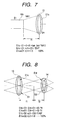
- Fig. 7 illustrates a case of the effective aperture D1 of the first convex lens 13 being sufficiently large, as an example.
- the beam size (E1s or D1) at transmitting through the first lens 13 and a beam size E1t at reaching the second lens 14 are specified by the ratio of the focal length f1 against f2 of the first and second convex lenses 13, 14.
- a take-in efficiency ⁇ 2 by the effective aperture D2 of the second convex lens 14 is expressed as follows.
- E1t D1 ⁇ f2/f1 (here, E1s > D1)
- E1t E1s ⁇ f2/f1 (here, E1s ⁇ D1)
- ⁇ 2 (D2/E1t) 2
- the effective aperture D2 of the second convex lens 14 is sufficiently large, the light beam of the beam size E1t transmits entirely through the lens, and the take-in efficiency ⁇ 2 becomes 1.0 (100 %).
- Fig. 8 illustrates a case that the light beam sufficiently taken in by the first convex lens 13 overflows from the effective aperture D2 of the second convex lens 14.
- a take-in efficiency ⁇ 3 of the PCF 18 is specified by the numerical aperture (NAu) of the convergent light and the numerical aperture (NA2) of the PCF 18 in addition to the beam size E1t.
- the take-in efficiency ⁇ 3 namely, the connection efficiency ⁇ is the multiplication of the two take-in efficiencies ⁇ 31, ⁇ 32, which is given by the following expressions.
- ⁇ 31 (E2/E2s) 2 (here, E2s > E2)
- ⁇ 31 1.0 (here, E2s ⁇ E2)
- E2s represents the beam size on the PCF 18. Provided that the core diameter E2 of the PCF 18 is larger than E2s, the light beam of the beam size entirely falls on the PCF 18, and the take-in efficiency ⁇ 31 becomes 1.0 (100 %).
- ⁇ 32 NA2/NAu (here, NAu > NA2)
- ⁇ 32 1.0 (here, NAu ⁇ NA2)
- the take-in efficiency ⁇ 3 is the total connection efficiency ⁇ of the optical fiber connector 10, and as shown by the expression (6) and Fig. 6, it is the connection efficiency ⁇ itself in the range where it is influenced by both of the numerical aperture NA and the beam size.
- Fig. 11 illustrates an optical system in which the beam size E1t falling on the second convex lens 14 does not exceed the effective aperture D2 of the second convex lens 14, which is opposite to the case in Fig. 10.
- the beam size E2s on the PCF 18 is acquired from the proportional relation between the beam size at the first convex lens 13 and the beam size E1t at the second convex lens 14, which is expressed as follows.
- E1 : E2s E1s : E1t
- W 2 ⁇ f1 ⁇ NA1
- NAu sin(tan -1 W/2 ⁇ f2)
- NAu sin(tan-1D2/2 ⁇ f2)
- NAu sin(tan-1D1/2 ⁇ f2)
- the effective aperture D1 of the first convex lens 13 and the effective aperture D2 of the second convex lens 14 will be discussed as the factors that give influences to the optical fiber connector.
- the effective aperture D1 of the first convex lens 13 is smaller than a specific size, the light emitted from the PCF 16S is restrained by the effective aperture D1 of the first convex lens 13, and the beam to the second convex lens 14 and the POF 18 is limited.
- connection efficiency ⁇ at the POF 18 is affected by ⁇ 1 of the expression (8), it becomes the expression (16) multiplied by the expression (B), which is expressed as follows.
- the effective aperture D2 of the second convex lens 14 is smaller than a specific size, the light emitted from the first convex lens 13 is restrained by the effective aperture D2 of the second convex lens 14, and the beam to the POF 18 is limited.
- connection efficiency ⁇ is affected by ⁇ 2 of the expression (11), it becomes the expression (16) multiplied by the expression (11), which is expressed as follows.
- the model A is made up with the following data : the core diameter E1 of the POF 16S being 1 mm, the numerical aperture NA1 of the POF 16S being 0.15, the effective aperture D1 of the first convex lens 13 being sufficiently large, the focal length f1 being 5 mm, the effective aperture D2 of the second convex lens 14 being sufficiently large, the focal length f2 being 1 mm, the core diameter E2 of the PCF 18 being 0.2 mm, and the numerical aperture NA2 of the PCF 18 being 0.33.
- x 1, which implies the maximum efficiency ⁇ a shown in Fig. 6.
- E1 NA1 E2 NA2 x f1 f2 0.15 0.2 0.33 1 5 1 mm mm mm mm
- connection efficiency ⁇ of the fibers is satisfied with a desirable value of approximately 0.5 (50 %).
- the optical fiber connector 10 of the invention has been described by using the model cases.
- the POF 16 is an integration of the POF 16S and the convex lens 16, as shown in Fig. 1, which is equivalent to one formed by polishing the front end of the POF 16S into a convex lens-shape.
- This convex part 16c being the front end of the POF 16 will be explained on the basis of Fig. 16.
- the POF 16 can be applied to the optical fiber connector 10 shown in Fig. 16 as it is.
- the model C is made up with the following data : the core diameter E1 of the POF 16 being 1 mm, the numerical aperture NA1 of the POF 16 being 0.15, the refractive index n1 being 1.5, the lens-shaped radius r1 of the front end of the core 16a being 2.5 mm, the core diameter E2 of the PCF 18 being 0.2 mm, and the numerical aperture NA2 of the PCF 18 being 0.33.
- the model C will be the same optical fiber connector as the model A.
- the model D is made up with the following data : the core diameter E1 of the POF 16 being 0.75 mm, the numerical aperture NA1 of the POF 16 being 0.2, the refractive index n1 being 1.5, the lens-shaped radius r1 of the front end of the core 16a being 1.875 mm, the core diameter E2 of the PCF 18 being 0.2 mm, and the numerical aperture NA2 of the PCF 18 being 0.33.
- the model D will be the same optical fiber connector as the model B.
- it may be a combination of two plastic fibers each having different diameters.
- it is only needed to use the plastic fibers by polishing both the front ends thereof into spherical shaped-lenses.
- the optical fiber connector of this invention exhibits a high connection efficiency of the fibers in the region shown by the slant lines in Fig. 6. Therefore, to set the values of the factors that enter the region will achieve the apparatus of a predetermined connection efficiency.
- the optical fiber connector of the invention includes a first optical fiber, a first lens that converges a light emitted from the first optical fiber, a second lens that converges a light emitted from the first lens, and a second optical fiber that receives a convergent light from the second lens.
- the connection efficiency ⁇ of the first and the second optical fibers satisfies the following inequality: (E1/E2) 2 ⁇ ⁇ ⁇ NA2/sin(tan -1 E1/E2 ⁇ NA1/x), in 0 ⁇ x ⁇ 1; (E1/E2) 2 ⁇ ⁇ ⁇ (1/x) 2 ⁇ NA2/sin(tan -1 E1/E2 ⁇ NA1/x), in 1 ⁇ x ⁇ E1/E2 ⁇ NA1/sin (tan -1 NA2) ; or (E1/E2) 2 ⁇ ⁇ ⁇ (1/x) 2 , in E1/E2 ⁇ NA1/sin (tan -1 NA2) ⁇
- the optical fiber connector of the invention can significantly enhance the connection efficiency compared with the direct connection of the fist and second optical fibers, and can transmit lights between remotely located places under an optimized condition, since it is designed to make the diameter of the first optical fiber differ from the diameter of the second optical fiber, and to adjust either one of the numerical apertures and the beam sizes of the fist and second optical fibers, or variable factors of the numerical apertures and the beam sizes.
- the connection efficiency is the foregoing ⁇ multiplied by ⁇ 1 and/or ⁇ 2.
- the invention can achieve such a magnitude of connection efficiency that the divergent light and the convergent light by either one or both of the effective apertures of the first and second lenses are taken into consideration.
- the first lens is made by forming the end face of the first optical fiber into a spherical face
- the second lens is made by forming the end face of the second optical fiber into a spherical face.
- either one of the first and the second lenses is made by forming the end face of the first or the second optical fiber into a spherical face.
- the invention can form an optical fiber connector with a reduced number of the lens member, reduce the number of the components, assemble with a high accuracy, since the alignment work of the lenses is reduced, and better the connection efficiency of the optical fibers.
Landscapes
- Physics & Mathematics (AREA)
- General Physics & Mathematics (AREA)
- Optics & Photonics (AREA)
- Optical Couplings Of Light Guides (AREA)
Applications Claiming Priority (2)
| Application Number | Priority Date | Filing Date | Title |
|---|---|---|---|
| JP964299 | 1999-01-18 | ||
| JP11009642A JP2000206359A (ja) | 1999-01-18 | 1999-01-18 | 光ファイバ結合装置 |
Publications (2)
| Publication Number | Publication Date |
|---|---|
| EP1020742A2 true EP1020742A2 (de) | 2000-07-19 |
| EP1020742A3 EP1020742A3 (de) | 2003-08-06 |
Family
ID=11725886
Family Applications (1)
| Application Number | Title | Priority Date | Filing Date |
|---|---|---|---|
| EP00100814A Withdrawn EP1020742A3 (de) | 1999-01-18 | 2000-01-17 | Faseroptischer Stecker |
Country Status (3)
| Country | Link |
|---|---|
| US (1) | US6282347B1 (de) |
| EP (1) | EP1020742A3 (de) |
| JP (1) | JP2000206359A (de) |
Cited By (4)
| Publication number | Priority date | Publication date | Assignee | Title |
|---|---|---|---|---|
| WO2012011943A1 (en) * | 2010-07-23 | 2012-01-26 | Tyco Electronics Corporation | Imaging interface for optical components |
| WO2015086272A1 (en) * | 2013-12-09 | 2015-06-18 | Koninklijke Philips N.V. | Optical fiber connector |
| WO2017015279A1 (en) * | 2015-07-20 | 2017-01-26 | Samtec, Inc. | Eye-safe interface for optical connector |
| US10031297B2 (en) | 2013-12-09 | 2018-07-24 | Koninklijke Philips N.V. | Optical fiber connector validation |
Families Citing this family (18)
| Publication number | Priority date | Publication date | Assignee | Title |
|---|---|---|---|---|
| US6438290B1 (en) * | 2000-06-22 | 2002-08-20 | Eastman Kodak Company | Micro-aspheric collimator lens |
| CN1541340A (zh) * | 2001-06-15 | 2004-10-27 | 康宁股份有限公司 | 热形成的透镜型纤维 |
| CN1332228C (zh) | 2001-06-15 | 2007-08-15 | 康宁股份有限公司 | 用于聚焦和聚光器应用的锥形透镜光纤 |
| US6655850B2 (en) * | 2001-07-05 | 2003-12-02 | Corning Incorporated | Hybrid fiber expanded beam connector and methods for using and making the hybrid fiber expanded beam connector |
| US20040101238A1 (en) * | 2002-11-22 | 2004-05-27 | Coleman Christopher L | Fiber optic coupling system and method for improved alignment tolerances |
| US7099535B2 (en) * | 2002-12-31 | 2006-08-29 | Corning Incorporated | Small mode-field fiber lens |
| CN102375183A (zh) * | 2010-08-24 | 2012-03-14 | 富士康(昆山)电脑接插件有限公司 | 光纤连接器组件 |
| GB201116675D0 (en) * | 2011-09-28 | 2011-11-09 | Bae Systems Plc | Plastic optical fibres |
| JP6068859B2 (ja) * | 2012-07-31 | 2017-01-25 | 株式会社ディスコ | レーザー加工装置 |
| RU2620783C9 (ru) * | 2015-09-07 | 2017-07-26 | Российская Федерация, от имени которой выступает Государственная корпорация по атомной энергии "Росатом" (Госкорпорация "Росатом") | Устройство ввода импульсного лазерного пучка в волоконно-оптическую линию связи |
| TWI613475B (zh) * | 2016-12-02 | 2018-02-01 | 財團法人工業技術研究院 | 光纖耦合器 |
| JP2019203946A (ja) * | 2018-05-22 | 2019-11-28 | 三菱重工業株式会社 | ファイバ結合装置及びレーザ加工装置 |
| JP2022013191A (ja) * | 2020-07-03 | 2022-01-18 | パナソニックIpマネジメント株式会社 | 光ファイバ部材、及びファイバセンサ |
| JP2023041513A (ja) * | 2021-09-13 | 2023-03-24 | 富士通オプティカルコンポーネンツ株式会社 | 光デバイス |
| DE102022102057B4 (de) | 2022-01-28 | 2024-01-18 | Huber+Suhner Cube Optics Ag | Lichtwellenleiterstecker sowie Lichtwellenleiterverbinder mit einem solchen |
| DE102023118609B4 (de) * | 2023-07-13 | 2025-05-15 | Huber+Suhner Cube Optics Ag | Multilichtwellenleiterstecker sowie Lichtwellenleiterverbinder mit einem solchen |
| DE102023118608B4 (de) * | 2023-07-13 | 2025-05-15 | Huber+Suhner Cube Optics Ag | Rückreflexionsverminderter Lichtwellenleiterstecker sowie Lichtwellenleiterverbinder mit einem solchen |
| US20250028125A1 (en) * | 2023-07-21 | 2025-01-23 | Cisco Technology, Inc. | Large-na connector for cpo applications |
Family Cites Families (9)
| Publication number | Priority date | Publication date | Assignee | Title |
|---|---|---|---|---|
| GB1429843A (en) * | 1973-06-02 | 1976-03-31 | Plessey Co Ltd | Endwise coupling of light guides |
| GB1504490A (en) * | 1975-11-28 | 1978-03-22 | Bowthorpe Hellerman Ltd | Optical fibre connector |
| US4304461A (en) * | 1977-07-19 | 1981-12-08 | Plessey Handel Und Investments Ag. | Optical fibre connectors |
| CH622355A5 (de) * | 1978-05-23 | 1981-03-31 | Battelle Memorial Institute | |
| US5026206A (en) * | 1990-03-30 | 1991-06-25 | Oconnor Patrick L | Pavement and base recycle method and apparatus |
| GB9102715D0 (en) * | 1991-02-08 | 1991-03-27 | Smiths Industries Plc | Optical fibre couplings |
| FR2718854B1 (fr) * | 1994-04-13 | 1996-07-12 | France Telecom | Procédé de préparation d'une fibre optique en vue d'un couplage avec un phototransducteur et système optique ainsi obtenu. |
| US5699464A (en) * | 1996-05-13 | 1997-12-16 | Lucent Technologies Inc. | Lens structure for focusing the light emitted by a multimode fiber |
| US5940564A (en) * | 1997-08-05 | 1999-08-17 | Picolight, Inc. | Device for coupling a light source or receiver to an optical waveguide |
-
1999
- 1999-01-18 JP JP11009642A patent/JP2000206359A/ja not_active Withdrawn
-
2000
- 2000-01-17 EP EP00100814A patent/EP1020742A3/de not_active Withdrawn
- 2000-01-18 US US09/484,628 patent/US6282347B1/en not_active Expired - Fee Related
Cited By (10)
| Publication number | Priority date | Publication date | Assignee | Title |
|---|---|---|---|---|
| WO2012011943A1 (en) * | 2010-07-23 | 2012-01-26 | Tyco Electronics Corporation | Imaging interface for optical components |
| CN103119489A (zh) * | 2010-07-23 | 2013-05-22 | 泰科电子公司 | 用于光学部件的成像接口 |
| US8457458B2 (en) | 2010-07-23 | 2013-06-04 | Tyco Electronics Corporation | Imaging interface for optical components |
| CN103119489B (zh) * | 2010-07-23 | 2016-08-03 | 泰科电子公司 | 用于光学部件的成像接口 |
| WO2015086272A1 (en) * | 2013-12-09 | 2015-06-18 | Koninklijke Philips N.V. | Optical fiber connector |
| CN105814469A (zh) * | 2013-12-09 | 2016-07-27 | 皇家飞利浦有限公司 | 光纤连接器 |
| US10031297B2 (en) | 2013-12-09 | 2018-07-24 | Koninklijke Philips N.V. | Optical fiber connector validation |
| CN105814469B (zh) * | 2013-12-09 | 2018-12-25 | 皇家飞利浦有限公司 | 光纤连接器 |
| US10379290B2 (en) | 2013-12-09 | 2019-08-13 | Koninklijke Philips N.V. | Optical fiber connector |
| WO2017015279A1 (en) * | 2015-07-20 | 2017-01-26 | Samtec, Inc. | Eye-safe interface for optical connector |
Also Published As
| Publication number | Publication date |
|---|---|
| US6282347B1 (en) | 2001-08-28 |
| JP2000206359A (ja) | 2000-07-28 |
| EP1020742A3 (de) | 2003-08-06 |
Similar Documents
| Publication | Publication Date | Title |
|---|---|---|
| US6282347B1 (en) | Optical fiber connector | |
| US7068883B2 (en) | Symmetric, bi-aspheric lens for use in optical fiber collimator assemblies | |
| US3874783A (en) | Numerical aperture expansion in fiber optic devices | |
| US6963682B2 (en) | Beam altering fiber lens device and method of manufacture | |
| US6744566B2 (en) | Symmetric, bi-aspheric lens for use in transmissive and reflective optical fiber components | |
| WO2001075492A2 (en) | Optical system including coupler for transmitting light between a single fiber light guide and multiple single fiber light guides | |
| EP3640691A2 (de) | Leistungsstarker raumfilter | |
| US20020057873A1 (en) | Laser collimator for a free space optical link | |
| US4600267A (en) | Optical distributor | |
| US6654518B1 (en) | Tap output collimator | |
| US6312163B1 (en) | Optical fiber connector | |
| US5301249A (en) | Catoptric coupling to an optical fiber | |
| US7206140B2 (en) | Lens, lens array and optical receiver | |
| US20250012973A1 (en) | Interface structure, optical connector, transmitter, receiver, optical cable, and optical communication system | |
| US20020114568A1 (en) | Optical fiber termination collimator and process of manufacture | |
| US4796969A (en) | Fiber optic relay connector | |
| JP6540310B2 (ja) | 光ファイバ端末 | |
| US20250020867A1 (en) | Multi-optical waveguide plug and optical waveguide connector comprising the plug | |
| US20080137519A1 (en) | Multi-channel optical communication lens system and optical module using the same | |
| RU2638095C1 (ru) | Моностатический оптический приемопередатчик | |
| US4995694A (en) | Fiber optical beam splitting device | |
| CA1272626A (en) | Fiber optic relay connection | |
| US6945710B2 (en) | Optical sub-assembly module for suppressing optical back-reflection and effectively guiding light from light source to optical waveguide | |
| RU2807465C1 (ru) | Способ отвода части мощности оптического излучения через боковую поверхность изогнутого волоконного световода | |
| JP2004309896A (ja) | 光ファイバー用コリメータレンズおよび光結合器 |
Legal Events
| Date | Code | Title | Description |
|---|---|---|---|
| PUAI | Public reference made under article 153(3) epc to a published international application that has entered the european phase |
Free format text: ORIGINAL CODE: 0009012 |
|
| AK | Designated contracting states |
Kind code of ref document: A2 Designated state(s): AT BE CH CY DE DK ES FI FR GB GR IE IT LI LU MC NL PT SE |
|
| AX | Request for extension of the european patent |
Free format text: AL;LT;LV;MK;RO;SI |
|
| PUAL | Search report despatched |
Free format text: ORIGINAL CODE: 0009013 |
|
| RIC1 | Information provided on ipc code assigned before grant |
Ipc: 7G 02B 6/26 B Ipc: 7G 02B 6/32 A |
|
| AK | Designated contracting states |
Designated state(s): AT BE CH CY DE DK ES FI FR GB GR IE IT LI LU MC NL PT SE |
|
| AX | Request for extension of the european patent |
Extension state: AL LT LV MK RO SI |
|
| 17P | Request for examination filed |
Effective date: 20030818 |
|
| 17Q | First examination report despatched |
Effective date: 20031119 |
|
| AKX | Designation fees paid |
Designated state(s): DE FR GB |
|
| STAA | Information on the status of an ep patent application or granted ep patent |
Free format text: STATUS: THE APPLICATION IS DEEMED TO BE WITHDRAWN |
|
| 18D | Application deemed to be withdrawn |
Effective date: 20041119 |