EP1020794A2 - Unité de contrôle électronique possédant un programme de commande orienté objet avec des besoins réduits en mémoire pour la communication entre objets - Google Patents
Unité de contrôle électronique possédant un programme de commande orienté objet avec des besoins réduits en mémoire pour la communication entre objets Download PDFInfo
- Publication number
- EP1020794A2 EP1020794A2 EP00100576A EP00100576A EP1020794A2 EP 1020794 A2 EP1020794 A2 EP 1020794A2 EP 00100576 A EP00100576 A EP 00100576A EP 00100576 A EP00100576 A EP 00100576A EP 1020794 A2 EP1020794 A2 EP 1020794A2
- Authority
- EP
- European Patent Office
- Prior art keywords
- message
- memory block
- processing
- stored
- storing
- Prior art date
- Legal status (The legal status is an assumption and is not a legal conclusion. Google has not performed a legal analysis and makes no representation as to the accuracy of the status listed.)
- Withdrawn
Links
Images









Classifications
-
- G—PHYSICS
- G06—COMPUTING OR CALCULATING; COUNTING
- G06F—ELECTRIC DIGITAL DATA PROCESSING
- G06F9/00—Arrangements for program control, e.g. control units
- G06F9/06—Arrangements for program control, e.g. control units using stored programs, i.e. using an internal store of processing equipment to receive or retain programs
- G06F9/46—Multiprogramming arrangements
- G06F9/54—Interprogram communication
- G06F9/546—Message passing systems or structures, e.g. queues
Definitions
- This invention relates to electronic control units, and more particularly to a control unit for controlling multiple control objects in accordance with an object-oriented program in a manner that minimizes the amount of required memory storage space for queuing of inter-object messages.
- an electronic control unit for a vehicle engine includes an engine control program with various types of control schemes.
- each of the programs includes programming code that is redundant with that of other programs, additional memory is required to store the programs, and program development time is increased.
- identical control code for driving injectors fuel injection valves
- control specifications have to be changed for these redundant code specifications have to be changed for these redundant code sections
- Object-oriented programming enables the above-mentioned programming code redundancies to be greatly reduced.
- Such programming includes several objects, with each object being a software module formed by bringing together data and a program (hereinafter called a method) for processing that data.
- a program hereinafter called a method
- all the functions of a control program are fractionalized into unit functions, and objects are prepared for those unit functions.
- message exchanges are carried out between objects, thereby enabling the objects to be linked together.
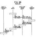
- Fig. 28 a program for controlling engine idling speed based on object-oriented programming will be described.
- objects are represented by vertical lines, and message exchanges between these objects are represented by left-right direction arrows.
- the rectangular boxes on the object lines represent object processing.
- the ISC object is an object for calculating a target throttle aperture for bringing the engine speed to an optimum idling speed based on the engine water temperature value.
- the water temperature sensor object is an object for converting a digital value obtained by A/D-converting an analog signal from an engine water temperature sensor into a water temperature value.
- the A/D-converter object is an object for controlling an A/D-converter for converting the analog signal from the water temperature sensor into a digital value.
- the throttle controller object is an object for controlling the throttle valve of the engine to the target throttle aperture calculated by the ISC object.
- the ISC object starts to operate (that is, the CPU starts to execute a method of the ISC object). Then, as shown by [1] of Fig. 28, the ISC object sends a water temperature acquisition request message to the water temperature sensor object.
- the water temperature sensor object operates, and as shown by [2] of Fig. 28, sends a water temperature A/D value acquisition request message to the A/D-converter object.
- the A/D-converter object converts the analog signal from the water temperature sensor into a digital signal.
- the A/D-converter object when it has finished the above-mentioned computation, as shown by [3] of Fig. 28, sends a water temperature A/D value acquisition response message (that is, a message to the effect that digital conversion of the water temperature sensor has finished) to the water temperature sensor object.
- the water temperature sensor object calculates a water temperature value based on the computation results of the A/D-converter object. After this calculation, as shown by [4] of Fig. 28, the water temperature sensor object sends a water temperature acquisition response message (that is, a message to the effect that the calculation of a water temperature value has finished) to the ISC object.
- the ISC object calculates a target throttle aperture based on the water temperature value thus calculated.
- the ISC object then sends a throttle setting request message (that is, a message showing that the target throttle aperture has been calculated) to the throttle controller object as shown by [5] of Fig. 28.
- the throttle controller object operates, and controls a throttle valve of the engine to the calculated target throttle aperture.
- the engine speed is thereby controlled to an optimum idling speed.
- inter-object processing request exchange inter-object message communication
- function calls as shown in Fig. 29, a command calling the object method to be processed next is pre-written.
- a command calling another object method is pre-written in the called object method.
- a method of an object B is called. Further, during execution of the method of the object B, a method of an object C is called. That is, by function calls, messages constituting processing requests are dispatched to other objects.
- memory is not secured for storing specific data, but is secured when necessary, and is released when not needed
- static while the microcomputer is operating, memory is secured for exclusive use in correspondence with content to be stored
- memory can be secured universally, irrespective of the content (size/number) of the data, and limited memory resources can be utilized effectively.
- memory area is managed by the computer operating system (OS).
- OS computer operating system
- system calls such as memory area acquisition and release commands are executed with respect to the OS, and the processing load of the program is large, because memory area provision is secured universally, irrespective of the content (size/number) of the data. Therefore, it is desirable for memory to be managed statically to increase the operating speed, and to be constructed so that it can be actively managed.
- an object of the present invention to provide an electronic control unit capable of executing object-oriented programming to control a control target in real time with minimum memory requirements compared to the memory requirements of conventional control programs.
- An electronic control unit includes a plurality of unit processors for respectively carrying out processing, in accordance with objects of an object-oriented program, for realizing unit functions that control the objects.
- the unit processors are realized by the processor of a microcomputer operating in accordance with an object-oriented program. That is, the processor executes a method of an object to carry out processing for realizing a function allocated to that object.
- one of the plurality of unit processors selectively carries out a processing operation, and, by the various unit processors dispatching messages constituting processing requests to other unit processors, the unit processors that are the output destinations of those messages carry out processing.
- the electronic control unit of the present invention secures in advance a storage memory area for exclusive use, and stores messages dispatched by the unit processor in this dedicated memory area. Also, the electronic control unit reads a message stored in the message dedicated memory area, and starts processing in whichever of the unit processors is the output destination of the read message.
- memory can be used without the need for reliance on an operating system. Therefore, it is possible to process objects obtained by fractionalizing a program for controlling a control object at a high operating speed into unit functions. Furthermore, because only messages required to start the processing of the unit processors are stored in the memory area secured for exclusive use, the amount of memory that should be secured can be estimated easily, thereby making it possible to reduce the amount of required memory.
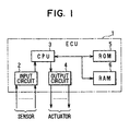
- Fig. 1 is a block diagram of the hardware of an electronic control unit 1 (ECU) mounted in a motor vehicle for controlling an internal combustion engine.
- the ECU 1 has a CPU 3 which computes optimum control values for the engine based on input signals from various sensors, such as a water temperature sensor for detecting the water temperature of the engine and a crank sensor for detecting the speed of the engine.
- the CPU 3 outputs control signals based on the computed results.
- the ECU 1 also includes an input circuit 2 which inputs signals from the various sensors to the CPU 3, and an output circuit which receives and outputs control signals from the CPU 3 for driving actuators such as a throttle valve and engine fuel injection valves.
- a nonvolatile ROM 5 stores programs that the CPU 3 executes to control the engine as well as data utilized in the execution of those programs, and a volatile RAM 6 temporarily stores computation results of the CPU 3.
- the main parts of a microcomputer include the CPU 3, the ROM 5 and the RAM 6. Part of the storage area of the RAM 6 is set as backup RAM capable of holding stored content even when the power supply to the ECU 1 has been cut off.
- a debug tool 7 is connected to the input and output circuits 2, 4 from outside the ECU 1 to determine whether a program executed by the CPU 3 is operating properly. When the debug tool 7 is connected to the input-output circuit 2, the CPU 3 performs predetermined processing for program operation checking when there is a flag DEBUG inside the RAM 6.
- the programs and data for engine control stored in the ROM 5 and executed by the CPU 3 are programmed based on object-oriented programming.
- the message delivery control part 10 shown in Fig. 2 is provided to realize inter-object message communication previously mentioned.
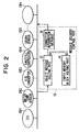
- Fig. 2 shows the relationship between engine control objects stored in the ROM 5 and the message delivery control part 10.
- the message delivery control part 10 is not hardware-implemented, but rather is realized by the CPU 3 operating in accordance with an object for message delivery control stored in the ROM 5. As a result, the message delivery control part 10 will be described using the example of a program part for controlling the engine idling speed.
- An ISC object OB1 for calculating a target throttle aperture for bringing the engine speed to an optimum idling speed based on the water temperature value and the actual engine speed; a water temperature sensor object OB2 for converting a digital value obtained by A/D-converting an analog signal from the water temperature sensor into a water temperature value; an A/D-converter object OB3 for controlling an A/D-converter (not shown) for converting the analog signal from the water temperature sensor into a digital value; a crank sensor object OB5 for calculating the engine speed based on a signal from the crank sensor; and a throttle controller object OB4 for controlling the throttle valve of the engine to the target throttle aperture calculated by the ISC object.
- objects other than the above-mentioned objects OB1 - OB5 are stored in the ROM 5, including an object for realizing the function of the message delivery control part 10.
- the ISC object OB1 When a start request message is periodically dispatched to the ISC object OB1 from an object other than the objects OB1 - OB5 (for example every 4ms) to determine the timing of the idling speed control as shown at [1] of Fig. 3, the ISC object OB1 starts to operate (that is, the CPU 3 starts execution of the method of the ISC object OB1). Subsequently, as shown at [2], the ISC object OB1 outputs a water temperature acquisition request message to the water temperature sensor object OB2, and then, as shown at [3], dispatches an engine speed acquisition request message to the crank sensor object OB5.
- the water temperature sensor object OB2 operates and, as shown at [4], dispatches a water temperature A/D value acquisition request message to the A/D-converter object OB3.
- the crank sensor object OB5 calculates an engine speed based on the signal from the crank sensor.
- the crank sensor object OB5 then dispatches an engine speed acquisition response message (that is, a message to the effect that the calculation of the engine speed is finished) to the ISC object OB1 after finishing the calculation of the engine speed, as shown at [5] of Fig. 3.
- the A/D-converter object OB3 operates and converts the analog signal from the water temperature sensor into a digital value. As shown at [6] of Fig. 3, the A/D-converter object OB3, after finishing this computation, dispatches a water temperature A/D value acquisition response message (that is, a message that the digital conversion of the water temperature sensor is finished) to the water temperature sensor object OB2.
- a water temperature A/D value acquisition response message that is, a message that the digital conversion of the water temperature sensor is finished
- the water temperature sensor object OB2 calculates a water temperature value based on the computation result of the A/D-converter object OB3, and after that calculation, as shown at [7] of Fig. 3, dispatches a water temperature acquisition response message (that is, a message that the calculation of the water temperature value is finished) to the ISC object.
- the ISC object OB1 calculates a target throttle aperture based on the water temperature value calculated by the water temperature sensor object OB2 and the engine speed calculated by the crank sensor object OB5.
- the ISC object OB1 dispatches a throttle setting request message (that is, a message indicating that the target throttle aperture has been calculated) to the throttle controller object OB4.
- the throttle controller object OB4 operates and controls the throttle valve of the engine so that the calculated target throttle aperture is obtained, and thus the engine speed is controlled to an optimum idling speed.
- the processing sequence of the objects OB1 through OB5 is determined by virtual inter-object message communication wherein the objects OB1 - OB5 dispatch messages as processing requests to other objects and the objects that are the destinations to which those messages are output operate.
- the message delivery control part 10 for realizing this kind of inter-object message communication queues the messages that the objects dispatch. Whenever a predetermined delivery condition is established, the control part reads out the message which queued first among the queued messages, and delivers that message to the object that is the respective output destination.
- queuing refers to an action of inserting and storing data with respect to a queue, with a “queue” being a waiting line wherein insertion of data is carried out at one end of the data structure and deletion of data is carried out at the other end.
- delivery refers to the start of processing of the object that is the output destination of the message (specifically, execution of the method of the object specified by the message).
- the message delivery control part 10 has an object message holding part 12 for queuing messages from objects, and an empty memory block holding part 14 for providing this object message storing part 12 with storage area for storing (queuing) messages.
- the object message holding part 12 and the empty memory block holding part 14 provide storage area exclusively for messages in the RAM 6, and, as will be discussed later, the capacity of the storage area provided fluctuates dynamically.
- an object identification number (hereinafter, OID) indicating the output destination object of the message
- a method identification number (hereinafter, MID) indicating the method to be executed among the methods of the destination object
- OID object identification number
- MID method identification number
- an argument is also sometimes included; however, instead of an argument, an address at which data necessary for computation of the message transmission destination is stored may be included.
- the message delivery control part 10 has a connection information database 16 for specifying the delivery destination of a message read from the object message holding part 12.
- the database is for specifying the ROM holding address indicated by the OID and the MID of the method of the object.
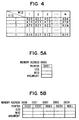
- connection information database 16 as shown in Fig. 4, consists of a data table having associated and stored combinations of OIDs and MIDs, and leading addresses of the ROM 5 at which the object methods designated by these combinations are held (that is, execution start addresses). For example, in the data table of Fig. 4, the object method whose OID is n and whose MID is m is held with the address "Anm" as its top in the ROM 5.
- the connection information database 16 made up of this kind of data table is pre-stored in the ROM 5 together with the objects.
- the above-mentioned message storage area is secured with a predetermined capacity matched to the amount of data in a message as units (a storage area of that unit capacity is called a memory block). That is, a predetermined number (for example 5) of memory blocks specified by the program are secured in the RAM 6 as storage area exclusively for messages.
- these memory blocks have an OID part for storing the OID of the message output destination, an MID part for storing the MID of the message output destination, and an argument part for storing an argument. Also, because a sequence from securing to releasing is decided in accordance with predetermined rules when memory blocks are secured in the object message holding part 12 and the empty memory block holding part 14, the memory block also has a pointer for specifying the memory address of the next memory block in the sequence in accordance with this order.
- the number of memory blocks secured will be standardized to five, and the order in which the blocks are released will be standardized to 0000, 0001, 0002, 0003 and 0004.
- the above number of memory blocks and release order is by way of example only.
- memory blocks in which messages (including, inter alia, an OID and an MID) have been written are secured in the object message holding part 12, and memory blocks in which messages have not been written (hereinafter called empty memory blocks) are secured in the empty memory block holding part 14.
- the number of memory blocks secured by the empty memory block holding part 14 decreases by one. Consequently, the number of memory blocks that the object message holding part 12 secures increases by one, and a message is stored in the added memory block.
- the memory block in which that message had been stored is returned from the object message holding part 12 to the empty memory block holding part 14.
- the memory address of the memory block to be released first is stored as a head address
- the memory address of the memory block to be released last is stored as a tail address
- the empty memory block holding part 14 stores 0000 as the head address and 0004 as the tail address
- the object message holding part 12 stores NULL as the head address and as the tail address.
- 0001, 0002, 0003, 0004, NULL are respectively written into the pointers of the memory blocks (empty memory blocks) of the memory addresses 0000 - 0004.
- the object message holding part 12 stores 0000 as its head address and 0001 as its tail address
- the empty memory block holding part 14 stores 0002 as its head address and 0004 as its tail address.
- OIDa, OIDb, MIDa, MIDb are the OIDs and MIDs of the output destinations of the queued messages.
- the object message holding part 12 stores 0000 as its head address and 0004 as its tail address
- the empty memory block holding part 14 stores NULL as its head address and as its tail address.
- OID c - g and MID c - g are the OIDs and MIDs of the output destinations of the queued messages.
- the empty memory block holding part 14 releases a memory block by writing in its head address the memory address of the memory block to be released following the memory block of the memory address stored as its head address. After that, it writes the OID, MID and argument of the received message in the respective locations in the released memory block. Then, the pointer of the memory block of the memory address that had until now been stored as the tail address of the object message holding part 12 is rewritten from NULL to the memory address of the memory block to be newly secured, and the pointer of the newly secured memory block is made NULL. Finally, the memory address of the newly secured memory block is stored as the tail address of the object message holding part 12.
- the memory address of the memory block to be released following the memory block of the memory address that had been stored as the head address in the object message holding part 12 is re-stored as the head address, and the memory block is thereby released.
- the OID and the MID stored in the released memory block are then read in, and the message is delivered to the respective object.
- the pointer of the memory block of the memory address that had until now been stored as the tail address in the empty memory block holding part 14 is rewritten from NULL to the memory address of the released memory block, and NULL is written to the pointer of the memory block to be newly secured.
- the memory address of the memory block to be newly secured is stored as the tail address in the empty memory block holding part 14.
- all of the memory blocks secured in the RAM 6 are at first in the empty memory block holding part 14, and, when a message is dispatched from an object, one memory block is handed over (transferred) from the empty memory block holding part 14 to the object message holding part 12, and the message is stored in the transferred memory block.
- the memory block in which that message had been stored is returned from the object message holding part 12 to the empty memory block holding part 14 and is re-used.
- the message delivery control part 10 assumes an off state shown at 20 when the ignition switch of the vehicle has been turned off and the microcomputer of the ECU 1 has stopped operating. Then, when, for example, the ignition switch is turned on and an initialization request such as a reset applied to the microcomputer is generated, initialization processing is carried out as shown at 22. Thereafter, as shown at 24, the control part 10 assumes a message reception waiting state.
- the object message holding part 12 is initialized at S50. Specifically, as shown in Fig. 6A, the head address and the tail address stored in the object message holding part 12 are made NULL.
- the empty memory block holding part 14 is initialized. Specifically, first a number (in the present example, five) of empty memory blocks stipulated by the program is secured. Then, in accordance with the decided order of release (in this example, 0000, 0001, 0002, 0003, 0004), in the pointer of each memory block, the memory address of the memory block to be subsequently released is written (NULL in the pointer of the memory block of the memory address 0004). Then, the addresses predetermined as the head address and the tail address (in this example, the head address is 0000 and the tail address is 0004) are written to the empty memory block holding part 14. As a result, a state is assumed wherein, when a message has been dispatched from one of the objects, an empty memory block in the empty memory block holding part 14 can be transferred to the object message holding part 12.
- the message delivery control part 10 After the above initialization processing is finished, assumes a message reception waiting state.
- the message reception waiting state is a state wherein a message dispatched from an object can be queued in the object message holding part 12.
- the message delivery control part 10 carries out serialization processing as shown in Fig. 7D, and thereafter returns to the off state mentioned above.
- the object message holding part 12 is initialized at S70. Then at S80, the empty memory block holding part 14 is initialized as at S50 and S60 of the initialization processing of Fig. 8.
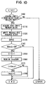
- the message delivery control part 10 carries out message queuing processing, and queues the above-mentioned message from an object in the object message holding part 12 before returning to the message reception waiting state.
- messages are output based on an object dispatching a message transmission request.
- a message transmission request for outputting that message (n, m) will be written "message transmission request (n, m)”.
- the message dispatched from the object this time is written in the acquired empty memory block. Specifically, the OID and MID, and possibly also an argument, comprising the content of the message are written in the empty memory block. Then, at S130, the memory block in which the message was written at S120 is queued in the object message holding part 12. That is, the memory address of the memory block in which the message was written is written to the pointer of the message block that had until now been secured at the end tail, and NULL is written to the pointer of the memory block in which the message was written. The memory address of the memory block in which the message was written is also stored as the tail address in the object message holding part 12.
- a flag DEBUG showing a debug state is OFF.
- a counter C is incremented by one at S150 to count the maximum value of the queuing messages during debugging.
- This counter C is a counter incremented by one during queuing processing of a message and decremented by one in message delivery processing, which will be further discussed later.
- the value of a maximum value Cmax of the number of queuing messages up to now is read from the RAM, and at S170 the sizes of the counter C and the maximum value Cmax are compared.
- the maximum value Cmax is replaced with the value of the counter C, and message queuing processing is ended.
- the counter value is smaller than the value of the maximum value Cmax, it is inferred that even if this queuing processing is ended, the maximum value Cmax which had been stored in the RAM will remain the maximum value, and message queuing processing is ended.
- Fig. 11 is an example wherein, as shown in Fig. 11A, the memory blocks of memory addresses 0000, 0001 are message blocks and the memory blocks of memory addresses 0002, 0003, 0004 are empty memory blocks.
- Fig. 12 is an example wherein, as shown in Fig. 12A, the memory blocks of memory addresses 0003, 0004 are message blocks and the memory blocks of memory addresses 0000, 0001, 0002 are empty memory blocks.
- OID k, m, n, p, q, r and MID k, m, n, p, q, r are the OIDs and MIDs of the messages.
- the memory block of the memory address stored as the head address in the empty memory block holding part 14 is selected (the memory block whose memory address is 0002 in the example of Fig. 11, 0000 in the example of Fig. 12). Then, as shown in Fig. 11B and Fig. 12B, the head address of the empty memory block holding part 14 is re-stored with the memory address of the next memory block (0003 in the example of Fig. 11, 0001 in the example of Fig. 12), and the pointer of the acquired memory block is deleted (S100: YES, S110).
- the content of the message dispatched from an object (OIDn, MIDn in the example of Fig. 11 and OIDr, MIDr in the example of Fig. 12) is written in this acquired empty memory block (S120), the memory address of the newly secured memory block (0002 in the example of Fig. 11 and 0000 in the example of Fig. 12) is written to the pointer of the memory block that had until now been the tail address (the memory block whose memory address was 0001 in the example of Fig. 11, 0004 in the example of Fig. 12), and NULL is written to the pointer of the newly acquired memory block.
- the memory block in which the message content was written (the memory block whose memory address is 0002 in the example of Fig. 11, 0000 in the example of Fig. 12) becomes the end tail of the memory blocks in the object message holding part 12, its memory address is stored as the tail address in the object message holding part 12.
- the number of message blocks secured in the object message holding part 12 increases by one, while the number of empty memory blocks secured in the empty memory block holding part 14 decreases by one.
- the empty memory block whose order of release initially was second in the empty memory block holding part 14 (the memory block whose memory address is 0003 in the example of Fig. 11, 0001 in the example of Fig. 12) becomes the head empty memory block, and the empty memory block which initially was third (the memory block whose memory address is 0004 in the example of Fig. 11, 0002 in the example of Fig. 12) becomes the second empty memory block.
- the message delivery control part 10 When in the message reception waiting state a message delivery request is dispatched from the object as shown at 30 in Fig. 7, the message delivery control part 10 assumes a message delivery state as shown at 32.
- message delivery state As shown at 34, if there is a message queued in the object message holding part 12, message delivery processing, which will be further discussed later, is carried out, and delivery of that queued message (that is, execution of the method of the object specified by the message) is performed. As shown in Fig. 36, if there is no message queued in the object message holding part 12, the message holding part returns to the message reception state.
- message delivery processing is carried out when a message delivery request has been dispatched from an object, or when the execution of a method of an object has finished.
- the head message block is acquired, and the contents of the message written in that message block (OID and MID) are read.
- the message block acquired at S230 is an empty memory block and is registered at the end of the queue in the empty memory block holding part 14.
- the leading address (execution start address) of the ROM 5 at which the method of the object corresponding to the OID and MID is calculated by searching from the above-mentioned connection information database 16.
- the execution start address calculated in S250 is then called.
- the program execution point of the CPU 3 shifts to the head of the method of the object corresponding to the message contents read at S230, and delivery of the message is carried out.
- the message delivery processing is again carried out from the above-mentioned S210.
- Fig. 14 is an example wherein at first, as shown in Fig. 14A, the memory blocks of memory addresses 0000, 0001, 0002 are message blocks, and the memory blocks of memory addresses 0003, 0004 are empty memory blocks.
- Fig. 15 is an example wherein at first, as shown in Fig. 15A, the memory blocks of memory addresses 0001, 0002 are message blocks and the memory blocks of memory addresses 0003, 0004, 0000 are empty memory blocks.
- OID h, i, j and MID h, i, j are the OIDs and MIDs of the messages.
- the memory block of the memory address stored as the head address in the object message holding part 12 is selected (the memory block whose memory address is 0000 in the example shown in Fig. 14, 0001 in the example shown in Fig. 15), and the memory address of the next memory block (0001 in the example shown in Fig. 14, 0002 in the example shown in Fig. 15) in the object message holding part 12 is stored therein as the head address, and the pointer of the acquired memory block is deleted (S230).
- the OID and MID stored in the acquired memory block (OIDh, MIDh in Fig. 14, OIDi, MIDi in Fig. 15) are then read, the content of the message is deleted, the memory address of the newly secured memory block (0000 in Fig. 14, 0001 in Fig. 15) is written to the pointer of the memory block that had previously been the tail address (the memory block whose memory address is 0004 in Fig. 14, 0000 in Fig. 15), and NULL is written to the pointer of the newly secured memory block.
- the memory block having become an empty memory block (the memory block whose memory address is 0000 in Fig. 14, 0001 in Fig. 15), 50 that it is at the end of the message blocks in the empty memory block holding part 14, has its memory address stored as the tail address in the empty memory block holding part 14 (5240).
- the number of empty memory blocks secured in the empty memory block holding part 14 increases by one, and the number of message blocks secured in the object message holding part 12 decreases by one. Also, the message block whose order of release initially was second in the object message holding part 12 (the memory block whose memory address is 0001 in Fig. 14, 0002 in Fig. 15), becomes the head empty memory block.
- the examples were given to show that the memory block of the memory address stored as the head address in the object message holding part 12 (or the empty memory block holding part 14) (the memory block released first among the memory blocks secured in the respective holding part) is acquired, and, after a message is written, read or deleted, it is registered as the tail address in the empty memory block holding part 14 (or the object message holding part 12).
- the debug tool 7 reads the maximum value Cmax value from the RAM 6 and reflects the read value in a memory block number specification location in the program.
- the ISC object OB1 has an idling throttle setting start request method (Fig. 18) executed along with a message (1, 2).
- this message has an OID of 1 and an MID of 2, and constitutes the throttle setting start request message shown by [1] of Fig. 3, a water temperature acquisition response method (Fig. 19) executed along with a message (1, 3) constituting the water temperature acquisition response message shown by [7] of Fig. 3, and an engine speed acquisition response method (Fig. 20) executed along with a message (1, 4) constituting the engine speed acquisition response message shown by [5] of Fig. 3.
- the water temperature sensor object OB2 has a water temperature acquisition request method (Fig. 21) executed along with a message (2, 1) constituting the water temperature acquisition request message shown by [2] in Fig. 3 and a water temperature A/D value acquisition response method (Fig. 22) executed along with a message (2, 2) constituting the water temperature A/D value acquisition response message shown by [6] in Fig. 3.
- the A/D-converter object OB3 has a water temperature A/D value acquisition request method (Fig. 23) executed along with a message (3, 0) constituting the water temperature A/D value acquisition request message shown by [4] of Fig. 3
- the throttle controller object OB4 has a throttle setting request method (Fig. 24) executed along with a message (4, 4) constituting the throttle setting request message shown by [8] of Fig. 3
- the crank sensor object OB5 has an engine speed acquisition request method (Fig. 25) executed along with a message (5, 0) constituting the engine speed acquisition request message shown by [3] of Fig. 3.
- the execution start addresses of the methods of the objects OB1 - OB5 are preregistered in the connection information database 16 respectively in association with the OIDs and MIDs indicating the indicated methods.
- the schedule processing of Fig. 17, which is an object other than the objects OB1 - OB5 mentioned above and is processing of an object for determining the timing of the idling speed control, is executed every 4ms.
- it will be assumed that it is debug processing, and that the flag DEBUG is ON. Accordingly, at S140 of the message queuing processing shown in Fig. 10, it will be assumed that an affirmative determination is always made. Further, it will be assumed that this schedule processing is executed after the initialization processing of Fig. 8 is carried out. Finally, it will be assumed that a sufficient number of empty memory blocks are set in the empty memory block holding part 14, and that at S100 of the message queuing processing shown in Fig. 10 an affirmative determination is always made.
- a message transmission request (1, 2) is dispatched. Consequently, the message queuing processing of Fig. 10 described above is executed, and a message (1, 2) is queued in the object message holding part 12. That is, at S110 of Fig. 10, the head empty memory block is acquired from the empty memory block holding part 14. At S120, the message (1, 2) is written into the acquired empty memory block, and, at S130, the memory block into which the message (1, 2) was written is registered as a message block in the object message holding part 12. In such a case, just the message block in which the message (1, 2) was written, is registered in the object message holding part 12.
- the execution start address A12 (see Fig. 16) of the idling throttle setting start request method of the ISC object OB1 corresponding to the contents of the message (1, 2) thus read is calculated from the connection information database 16, and at S260 that calculated execution start address is called. Thereby, delivery of the message (1, 2) is carried out, and execution of the idling throttle setting start request method shown in Fig. 18 is started.
- the head empty memory block is acquired from the empty memory block holding part 14.
- the message (5, 0) is written to that acquired empty memory block, and at S130, the memory block into which the message (5, 0) was written is registered as a message block at the tail (in this case, the second from the head) of the blocks in the object message holding part 12.
- the contents of the message (2, 1) are read from the message block at the head of the object message holding part 12.
- the message block in which the message (2, 1) had been written is returned to the empty memory block holding part 14 as an empty memory block.
- the execution start address A21 (see Fig. 16) of the water temperature acquisition request method of the water temperature sensor object OB2 corresponding to the contents of the message (2, 1) thus read is calculated from the connection information database 16.
- that calculated execution start address is called.
- the message queuing processing of Fig. 10 is executed, and the message (3, 0) is queued in the object message holding part 12 in exactly the same way as the procedure described above. Then, in the object message holding part 12, the message block in which the message (5, 0) was written and the message block in which the message (3, 0) was written are registered in that order. In other words, two messages, (5, 0) and (3, 0) are stored in the object message holding part 12 in that order. Therefore, at S150 the counter C is incremented by one, and because the count value C of the counter C at this time is 2, the maximum value Cmax is still 2.
- the contents of the message (5, 0) are read from the message block at the head of the object message holding part 12.
- the message block in which the message (5, 0) had been written is returned to the empty memory block holding part 14 as an empty memory block.
- the execution start address A50 (see Fig. 16) of the engine speed acquisition request method of the crank sensor object OB5 corresponding to the contents of the message (5, 0) thus read is calculated from the connection information database 16 and, at S260, that calculated execution start address is called. Delivery of the message (5, 0) is carried out, and execution of the engine speed acquisition request method shown in Fig. 25 is started.
- the message queuing processing of Fig. 10 is executed in exactly the same way as the procedure described above, and the message (1, 4) is queued in the object message holding part 12. Then, in the object message holding part 12, the message block in which the message (3, 0) was written and the message block in which the message (1, 4) was written are registered in that order. In other words, two messages, (3, 0) and (1, 4) are stored in that order in the object message holding part 12. Therefore, at S150 the counter C is incremented by one, and because the count value C of the counter C at this time is 2, the maximum value Cmax is still 2.
- the contents of the message (3, 0) are read from the message block at the head of the object message holding part 12.
- the message block in which the message (3, 0) had been written is returned to the empty memory block holding part 14 as an empty memory block.
- the execution start address A30 (see Fig. 16) of the water temperature A/D value acquisition request method of the A/D-converter object OB3 corresponding to the contents of the message (3, 0) thus read is calculated from the connection information database 16.
- the calculated execution start address is called.
- delivery of the message (3, 0) is carried out, and execution of the water temperature A/D value acquisition request method shown in Fig. 23 is started.
- the message queuing processing of Fig. 10 is executed, and the message (2, 2) is queued in the object message holding part 12 in exactly the same way as the procedure described above. Then, in the object message holding part 12, the message block in which the message (1, 4) was written and the message block in which the message (2, 2) was written are registered in that order. In other words, two messages, (1, 4) and (2, 2), are stored in the above order in the object message holding part 12. Therefore, at S150 the counter C is incremented by one, and, because the count value C of the counter C at this time is 2, the maximum value Cmax is still 2.
- the contents of the message (1, 4) are read from the message block at the head of the object message holding part 12.
- the message block in which the message (1, 4) had been written is returned to the empty memory block holding part 14 as an empty memory block.
- the execution start address A14 (see Fig. 16) of the engine speed acquisition response method of the ISC object OB1 corresponding to the contents of the message (1, 4) thus read is calculated from the connection information database 16.
- the calculated execution start address is called. Consequently, delivery of the message (1, 4) is carried out, and execution of the engine speed acquisition response method shown in Fig. 20 is started.
- the new engine speed value and water temperature value are read from the RAM 6.
- a target throttle aperture for bringing the engine speed to an optimum idling speed is calculated based on the engine speed and water temperature value read at S455.
- the target throttle aperture calculated at S460 is saved in the RAM 6, and at S470, a message transmission request (4, 4) is dispatched.
- the execution start address A22 (see Fig. 16) of the water temperature A/D value acquisition response method of the water temperature sensor object OB2 corresponding to the contents of the message (2, 2) thus read is calculated from the connection information database 16.
- that calculated execution start address is called. Thereby, delivery of the message (2, 2) is carried out, and execution of the water temperature A/D value acquisition response method shown in Fig. 22 is started.
- the water temperature value computed at S515 is saved in the RAM 6, and at S525, a message transmission request (1, 3) is dispatched.
- the contents of the message (1, 3) are read from the message block at the head of the object message holding part 12.
- the message block in which the message (1, 3) had been written is returned to the empty memory block holding part 14 as an empty memory block.
- the execution start address A13 (see Fig. 16) of the water temperature acquisition response method of the ISC object OB1 corresponding to the contents of the message (1, 3) thus read is calculated from the connection information database 16.
- the calculated execution start address is called. Thereby, delivery of the message (1, 3) is carried out, and execution of the water temperature acquisition response method shown in Fig. 19 is started.
- the contents of the message (4, 4) are read from the message block at the head of the object message holding part 12.
- the message block in which the message (4, 4) had been written is returned to the empty memory block holding part 14 as an empty memory block.
- the execution start address A44 (see Fig. 16) of the throttle setting request method of the throttle controller object OB4 corresponding to the contents of the message (4, 4) thus read is calculated from the connection information database 16.
- the calculated execution start address is called. Thereby, delivery of the message (4, 4) is carried out, and execution of the throttle setting request method shown in Fig. 24 is started.
- the debug tool 7 of Fig. 1 reads the Cmax value from the RAM 6 and reflects the read value in a memory block number specification location in the program.
- Cmax 2. Because it is known that the memory block number specification location in the program is rewritten to a value of 2 or higher, if two memory blocks are provided the processing described above can be carried out in an error-free manner. Therefore, it is possible to effectively secure memory blocks.
- the methods of the objects OB1 - OB5 are executed in the order of: [1] the idling throttle setting start request method (Fig. 18) of the ISC object OB1; [2] the water temperature acquisition request method (Fig. 21) of the water temperature sensor object OB2; [3] the engine speed acquisition request method (Fig. 25) of the crank sensor object OB5; [4] the water temperature A/D value acquisition request method (Fig. 23) of the A/D-converter object OB3; [5] the engine speed acquisition response method (Fig. 20) of the ISC object OB1; [6] the water temperature A/D value acquisition response method (Fig. 22) of the water temperature sensor object OB2; [7] the water temperature acquisition response method (Fig. 19) of the ISC object OB1; and [8] the throttle setting request method (Fig. 24) of the throttle controller object OB4. Processing for idling speed control is carried out in the order shown in the message sequence diagram of Fig. 3.
- the initialization processing of Fig. 8 is executed, and memory storage area (empty memory blocks) is secured exclusively for storage of messages (queuing) in the empty memory block holding part 14.
- Object-dispatched messages (message transmission requests) are stored and secured in the object message holding part 12. Then a message stored in the object message holding part 12 is read out, and processing shifts to execution of the method of the object that is the output destination of the read-out message.
- the methods of the objects can be executed at a high operating speed. Furthermore, because only messages are stored in a storage area (empty memory blocks) secured exclusively therefore, the capacity that should be secured is easy to estimate, thereby making it possible to minimize memory requirements.
- the amount of memory necessary during system maintenance is initially secured, are managed on the message delivery control part 10, and are actively operated therein.
- the degree of independence from the OS increases, thereby making it possible to eliminate overhead applied to system calls to the OS.
- a message stored in the object message holding part 12 is read, processing starts at the method of the object that is the output destination of that read-out message, and the read-out message is deleted from the object message holding part 12. More specifically, the memory block of the object message holding part 12 in which the read-out message had been written has its contents deleted and is returned to the empty memory block holding part 14. Consequently, it is possible to prevent unnecessary messages from remaining in the message storing means, thereby further minimizing memory requirements.
- the message queuing processing of Fig. 10 is executed, a message is stored (queued) in the object message holding part 12.
- the message delivery processing of Fig. 13 is executed, the contents of the message stored in the object message holding part 12 are read out, and a shift is made to execution of the method of the object that is the output destination of the read-out message.
- the object methods can be executed in real time. In other words, it is possible for the object methods to be executed in an event-driven fashion.
- a decided number of unit storage areas (empty memory blocks) with a memory capacity determined in correspondence with the data size of the messages are secured in the empty memory block holding part 14.
- the message queuing processing shown in Fig. 10 when one message has been delivered, one empty memory block is acquired from the empty memory block holding part 14, and the message contents are written.
- an OID object identification number
- an MID method identification number
- the object message holding part 12 stores an OID and an MID in a memory block.
- a shift is made to execution of the method of the object shown by the read-out identification codes. Consequently, because the messages stored in the memory blocks become fixed-format, the number of memory blocks that should be secured can be reduced.
- memory management can easily be carried out independently without relying on system call execution of securing and releasing of system-provided general-purpose memory.
- the ECU 1 of the present invention during debugging, the number of message blocks queuing in the object message holding part 12 is counted. Then, the largest value queued at once during debugging is obtained. From this value, the number of empty memory blocks secured in the empty memory block holding part 14 in the initialization processing of Fig. 8 is determined. Because it is possible to obtain the maximum message block queuing number by debug processing, obtaining the number of memory blocks that should be pre-secured is simplified.
- the number of message blocks queuing in the object message holding part 12 is counted, the largest value queued at once during debugging is obtained, and from this, the number of empty memory blocks secured in the empty memory block holding part 14 in the initialization processing of Fig. 8 is determined.
- the number of empty memory blocks secured in the empty memory block holding part 12 may be alternatively determined by counting the number of empty memory blocks (Figs. 26 and 27).
- a counter C' counting the number of empty memory blocks is decremented by one (S140; YES, S155). Then a C'min value is read in from RAM (S165). If the counter C' is smaller than C'min, then C'min is rewritten to the value of the counter C' (S175; YES, S185).
- all of the objects are stored in a single ROM 5.
- the objects are held on a plurality of ROMs, as holding position information in the connection information database 16, information of what execution start address of what ROM should be stored.
- an identification number is given to each object and to each method. However, it is also possible to utilize only one identification number.
- the pointer of the memory block of the memory address that had until present been stored as the tail address in the empty memory block holding part 14 is rewritten from NULL to the memory address of the released memory block.
- NULL is written to the pointer of the newly secured memory block, and the memory address of the newly secured memory block is stored as the tail address in the empty memory block holding part 14.
- the memory block that the object message holding part 12 released can alternatively be secured without being secured as the tail address (to become, for example, the head address).
- ECU 1 of the embodiment described above is for controlling a vehicle engine
- the present invention can be applied in exactly the same way to electronic control units for controlling other control objects, such as for example an automatic transmission or vehicle suspension.
- An electronic control unit that can carry out object-oriented program processing without consuming much memory.
- a message is dispatched due to execution of an object method, that message is stored (queued) in an object message holding part.
- message delivery processing is executed. If a message has been stored in the object message holding part (S210: YES), the number of queuing messages is counted (S220), the one message stored first is read out (S230), and a shift is made to execution of the method of the object that is the output destination of that message (S250, S260). As a result, only messages need to be stored, and the amount of stored information is small.
Landscapes
- Engineering & Computer Science (AREA)
- Software Systems (AREA)
- Theoretical Computer Science (AREA)
- Physics & Mathematics (AREA)
- General Engineering & Computer Science (AREA)
- General Physics & Mathematics (AREA)
- Multi Processors (AREA)
- Debugging And Monitoring (AREA)
Applications Claiming Priority (2)
| Application Number | Priority Date | Filing Date | Title |
|---|---|---|---|
| JP657499 | 1999-01-13 | ||
| JP657499 | 1999-01-13 |
Publications (2)
| Publication Number | Publication Date |
|---|---|
| EP1020794A2 true EP1020794A2 (fr) | 2000-07-19 |
| EP1020794A3 EP1020794A3 (fr) | 2006-08-23 |
Family
ID=11642114
Family Applications (1)
| Application Number | Title | Priority Date | Filing Date |
|---|---|---|---|
| EP00100576A Withdrawn EP1020794A3 (fr) | 1999-01-13 | 2000-01-12 | Unité de contrôle électronique possédant un programme de commande orienté objet avec des besoins réduits en mémoire pour la communication entre objets |
Country Status (1)
| Country | Link |
|---|---|
| EP (1) | EP1020794A3 (fr) |
Citations (1)
| Publication number | Priority date | Publication date | Assignee | Title |
|---|---|---|---|---|
| US5551035A (en) | 1989-06-30 | 1996-08-27 | Lucent Technologies Inc. | Method and apparatus for inter-object communication in an object-oriented program controlled system |
Family Cites Families (3)
| Publication number | Priority date | Publication date | Assignee | Title |
|---|---|---|---|---|
| US4325120A (en) * | 1978-12-21 | 1982-04-13 | Intel Corporation | Data processing system |
| US6587889B1 (en) * | 1995-10-17 | 2003-07-01 | International Business Machines Corporation | Junction manager program object interconnection and method |
| JP3663842B2 (ja) * | 1997-07-18 | 2005-06-22 | 株式会社デンソー | 自動車用電子制御装置 |
-
2000
- 2000-01-12 EP EP00100576A patent/EP1020794A3/fr not_active Withdrawn
Patent Citations (1)
| Publication number | Priority date | Publication date | Assignee | Title |
|---|---|---|---|---|
| US5551035A (en) | 1989-06-30 | 1996-08-27 | Lucent Technologies Inc. | Method and apparatus for inter-object communication in an object-oriented program controlled system |
Also Published As
| Publication number | Publication date |
|---|---|
| EP1020794A3 (fr) | 2006-08-23 |
Similar Documents
| Publication | Publication Date | Title |
|---|---|---|
| US7082601B2 (en) | Multi-thread execution method and parallel processor system | |
| US5606703A (en) | Interrupt protocol system and method using priority-arranged queues of interrupt status block control data structures | |
| US5386566A (en) | Inter-processor communication method for transmitting data and processor dependent information predetermined for a receiving process of another processor | |
| US5341476A (en) | Dynamic data distribution network with sink and source files for particular data types | |
| US5659701A (en) | Apparatus and method for distributed program stack | |
| US9047093B2 (en) | Data transfer bus communication to receive data by sending request instruction attached with identifier indicating processor and thread context identities | |
| US20040193693A1 (en) | Data processing apparatus and method fo operating a data processing apparatus | |
| US5134712A (en) | System for recovering failure of online control program with another current online control program acting for failed online control program | |
| JPH07101407B2 (ja) | スケジユーリング方法及び装置 | |
| JP2002533807A (ja) | 割込み/ソフトウエア制御スレッド処理 | |
| SE515265C2 (sv) | System och förfarande för behandling av signaldata samt kommunikationssystem omfattande ett signaldatabehandlingssystem | |
| WO2010026836A1 (fr) | Logiciel de commande pour une commande distribuée, et dispositif de commande électronique | |
| JP3687373B2 (ja) | 高信頼分散システム | |
| US6502001B1 (en) | Electronic control unit having reduced inter-object message memory requirements for object-oriented control program | |
| US5710923A (en) | Methods and apparatus for exchanging active messages in a parallel processing computer system | |
| JP3663950B2 (ja) | 自動車用電子制御装置 | |
| EP0892342A2 (fr) | Unité de commande électronique | |
| EP1020794A2 (fr) | Unité de contrôle électronique possédant un programme de commande orienté objet avec des besoins réduits en mémoire pour la communication entre objets | |
| EP0871119B1 (fr) | Procédé de communication de données | |
| EP0258650B1 (fr) | Système ordinateur parallèle apte à la transmission asynchrone de données | |
| JP2000267868A (ja) | 電子制御装置 | |
| JP2000311102A (ja) | 電子制御装置 | |
| JPH0863442A (ja) | マルチプロセッサシステム | |
| EP0578496B1 (fr) | Méthode d'exécution des tâches dans un système multiprocesseur | |
| JPS6182244A (ja) | タスク間デ−タ送受信方式 |
Legal Events
| Date | Code | Title | Description |
|---|---|---|---|
| PUAI | Public reference made under article 153(3) epc to a published international application that has entered the european phase |
Free format text: ORIGINAL CODE: 0009012 |
|
| AK | Designated contracting states |
Kind code of ref document: A2 Designated state(s): AT BE CH CY DE DK ES FI FR GB GR IE IT LI LU MC NL PT SE |
|
| AX | Request for extension of the european patent |
Free format text: AL;LT;LV;MK;RO;SI |
|
| PUAL | Search report despatched |
Free format text: ORIGINAL CODE: 0009013 |
|
| AK | Designated contracting states |
Kind code of ref document: A3 Designated state(s): AT BE CH CY DE DK ES FI FR GB GR IE IT LI LU MC NL PT SE |
|
| AX | Request for extension of the european patent |
Extension state: AL LT LV MK RO SI |
|
| 17P | Request for examination filed |
Effective date: 20060830 |
|
| AKX | Designation fees paid |
Designated state(s): DE ES FR GB |
|
| 17Q | First examination report despatched |
Effective date: 20080214 |
|
| STAA | Information on the status of an ep patent application or granted ep patent |
Free format text: STATUS: THE APPLICATION IS DEEMED TO BE WITHDRAWN |
|
| 18D | Application deemed to be withdrawn |
Effective date: 20140102 |