EP1021031A2 - Vorrichtung zur Detektion von Bildern - Google Patents
Vorrichtung zur Detektion von Bildern Download PDFInfo
- Publication number
- EP1021031A2 EP1021031A2 EP00100716A EP00100716A EP1021031A2 EP 1021031 A2 EP1021031 A2 EP 1021031A2 EP 00100716 A EP00100716 A EP 00100716A EP 00100716 A EP00100716 A EP 00100716A EP 1021031 A2 EP1021031 A2 EP 1021031A2
- Authority
- EP
- European Patent Office
- Prior art keywords
- images
- support
- acquisition
- light
- rest
- Prior art date
- Legal status (The legal status is an assumption and is not a legal conclusion. Google has not performed a legal analysis and makes no representation as to the accuracy of the status listed.)
- Ceased
Links
Images
Classifications
-
- H—ELECTRICITY
- H04—ELECTRIC COMMUNICATION TECHNIQUE
- H04N—PICTORIAL COMMUNICATION, e.g. TELEVISION
- H04N1/00—Scanning, transmission or reproduction of documents or the like, e.g. facsimile transmission; Details thereof
- H04N1/04—Scanning arrangements, i.e. arrangements for the displacement of active reading or reproducing elements relative to the original or reproducing medium, or vice versa
- H04N1/19—Scanning arrangements, i.e. arrangements for the displacement of active reading or reproducing elements relative to the original or reproducing medium, or vice versa using multi-element arrays
- H04N1/195—Scanning arrangements, i.e. arrangements for the displacement of active reading or reproducing elements relative to the original or reproducing medium, or vice versa using multi-element arrays the array comprising a two-dimensional [2D] array
- H04N1/19589—Optical means, e.g. an optical fibre bundle, for mapping the whole or a part of a scanned image onto the array
-
- H—ELECTRICITY
- H04—ELECTRIC COMMUNICATION TECHNIQUE
- H04N—PICTORIAL COMMUNICATION, e.g. TELEVISION
- H04N1/00—Scanning, transmission or reproduction of documents or the like, e.g. facsimile transmission; Details thereof
- H04N1/04—Scanning arrangements, i.e. arrangements for the displacement of active reading or reproducing elements relative to the original or reproducing medium, or vice versa
- H04N1/19—Scanning arrangements, i.e. arrangements for the displacement of active reading or reproducing elements relative to the original or reproducing medium, or vice versa using multi-element arrays
- H04N1/195—Scanning arrangements, i.e. arrangements for the displacement of active reading or reproducing elements relative to the original or reproducing medium, or vice versa using multi-element arrays the array comprising a two-dimensional [2D] array
Definitions
- the present invention relates to a device for the detection of images present on a support, suitable in particular for acquiring images, text and/or figures on paper documents for the purpose of carrying out various operations, such as for instance, filing or fax transmission or copying onto different paper support.
- a technique commonly employed for the detection of images on printed sheets consists of scanning successive portions of the sheet by means of an image detection device endowed with means for the acquisition of images and with at least one light source.
- Such means for the acquisition of images usually comprise a focusing element, or a suitable objective lens, and means for capturing the image, such as for instance, a linear sensor endowed with cells of the Charge Coupled Device (CCD) type.
- CCD Charge Coupled Device
- the scanning of such successive portions of the sheet is effected by imposing a relative motion between the means for the acquisition of images and the same sheet.
- the sheet is disposed in full on a transparent rest that constitutes the upper surface of a fixed case.
- a transparent rest that constitutes the upper surface of a fixed case.
- this fixed case are housed one or more sources of illumination and the aforesaid means for the acquisition of images.
- the latter, and usually the light source, are fixed to a carriage connected to a motor and a traction device that allows them to move under the transparent rest surface.
- the carriage, and with it the means for the acquisition of images move from top to bottom of the sheet effecting the scanning of the latter, or allowing the capture of the images present on successive bands of the sheet.
- the acquired images relating to the different bands of the sheet are assembled to restore the integrity of the representation of the same sheet.
- the scanning is effected by maintaining the means for the acquisition of images fixed and moving the sheet carrying the images are to be detected relative to them.
- the sheet is made to move over a transparent window on the fixed case by means of automatic tractor devices, the means for the acquisition of images and the light source being housed under this window, within and fixed to the fixed case.
- Such image detection devices are sometimes connected to an apparatus for the memorization and management of information to create document archives.
- information memorization and management apparatus could comprise electronic devices to process information in digital format, such as for instance, computers.
- Another drawback of many of the aforementioned type of detection devices consists in the dazzling of the operator when there is no screen above the sheet and the transparent rest surface to protect the eyes of the operator during the image scanning activity.
- the light source in fact, must be oriented in a such way as to achieve intense illumination of the portion of the sheet to be acquired. For this reason, the light source, often constituted by a tubular neon light, is made to move along the surface of the sheet synchronized with the movement of the means for the acquisition of images and the light is directed perpendicularly to the surface of the sheet.
- a further drawback of such image detection devices is the encumbrance, sometimes considerable, of the case within which they, together with the means for the acquisition of images and the light source, the devices for the movement of the sheet and/or of the means of acquisition, are housed.
- One objective of the present invention is to furnish a device for detection the images present on opaque or gloss supports that resolve the aforementioned drawbacks.
- Another objective of the present invention is to create an image detection device that is reliable and that requires little maintenance.
- a further objective of the present invention is to furnish an image detection device of reduced encumbrance.
- Yet another objective of the present invention is to create an image detection device for which the operator isn't forced to use a screen set above the sheet to be scanned to avoid being dazzled.
- the device for the detection of images present on a support comprises a case endowed with a flat transparent surface to rest the image support. Within the case are housed the means for the acquisition of images and at least one light source. During the simultaneous detection of the entire image present on the support, the means of illumination and the light source are fixed with respect to the same support.
- the means for the acquisition of images comprise means for the reflection of the images present on the support and means for the capture of such images. Between the means for the reflection and the means for the capture of the images there is interposed at least one image focusing element.
- the means for the reflection of the images comprise at least one flat mirror.
- the light source comprises a directional illuminator that generates light rays oblique to the plane of the support surface.
- the means for the reflection of the images defines an optical path for the image from the support to the focusing element of not less than 1 meter in length.
- the means for the capture of the image comprise at least one sensor formed by a matrix of cells of the CCD type and the focusing element comprises an optical lens.
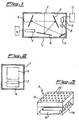
- the device according to the present invention comprises a case 1 to contain means for the acquisition of images and endowed with a flat transparent surface 2 for the rest of the image support, for instance, a paper sheet, of whose image, figures and/or text it is desired to acquire.
- the flat transparent surface 2 in particular, has substantially the same dimensions as the support to be acquired and could be equipped with guides, (not shown) to facilitate the positioning of the same document.
- the means for the acquisition of images housed within the case 1, comprise means for the reflection of the images, at least one focusing element 8 and means of capturing the images 9.
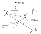
- the means for the reflection of the images comprise in their turn an arrangement of flat mirrors 4, 5, 6, 7 placed in mutual correspondence in such a way as to define, for the images present on the support, an optical path a, b, c, d, f from the transparent surface 2 to the means of focusing 8.
- the mirrors 4, 5, 6, 7 have such dimensions as to reflect the whole surface of the support in contact with the plane of support 2 and are so tilted within the case 1 to minimize the distorsion in the reflection of the images to be acquired.
- the number and the layout of the mirrors are selected on the basis of the focusing element 8 employed and of the dimensions of the support to be acquired and of the case 1.
- the focusing element 8 is preferably an optical lens of the type commonly employed in the photographic field.
- a photographic lens with a focal length of 35mm can be used as focusing element 8 without significant distortion in the images to be acquired.
- Such 35mm lenses are particularly inexpensive and easy to obtain.
- the transparent rest 2, and therefore, the support to be acquired, is illuminated by a light source 3 (illuminator), housed within the case 1, which projects light rays which fall on the surface 2 obliquely with respect to the plane of the same surface 2.
- a light source 3 luminator
- the light source 3 could also generate light of wavelength comprised within an interval that stretches above and/or below the wavelengths of visible light.
- such light could have wavelengths comprised within the interval of the infrared wavelength (from 0.75 ⁇ m to 1 mm).
- the means of capturing the images furthermore, preferably comprise a matrix sensor of the CCD type able to furnish a numerical representation of the captured images as output signal.
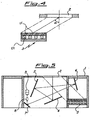
- the particular embodiment illustrated in the figures 1 and 2 also presents means 11 of memorization and management of the images, for instance, comprising one or more optical memorization supports connected to a computer working with a suitable memorized data management program.
- the support whose images are to be acquired is placed on the transparent plane 2 in a such way that the whole surface to be acquired is in contact with the same plane surface 2 and is faced toward the interior of the case 1.
- the support is then illuminated by the light source 3 and the whole surface to be acquired is reflected by the flat mirrors 4, 5, 6, 7, to the objective 8, along a path which is advantageously greater in length than a meter.
- the lens 8 in turn, focuses the reflected images of the whole surface of the support to be acquired on the means of image capture 9 comprising , for instance, a matrix sensor of the CCD type.
- the captured images could be filtered, for instance, by means of a specific driver resident on a card set downstream of the means for the capture of images 9, and filed through data processing apparatus.
- Figure 3 is a schematic representation of an illuminator 3 which generates light beams tilted with respect to the plane of rest 2 and, consequently, to the support to be acquired.
- the illuminator 3 comprises a perforated upper grate 13 fixed to a lower base 14 within which are housed lamps 12 that generate the light intensity necessary for the acquisition of the images.
- Such lamps 12 could be the common and inexpensive neon tubular lights.
- the grate 13 is equipped with holes 15 to project light bands in the direction of the rest plane 2 of the case 1.
- the holes 15, as indicated in figure 4, present axes tilted at an angle ⁇ with respect to the vertical to the plane 2 to illuminate the support in an oblique way.
- This angle ⁇ is between 35° and 55° inclusive and, preferably, equal to 42°.
- the inclination of the light rays directed toward the transparent plane 2 allows the operator to perform the activity of acquiring the images without needing to arrange a screen element above the support to be copied on the rest plane 2 to avoid being dazzled.
- the device described above can also be fitted, in particular when it is used for filing paper documents, with an automatic sheet feeding device for rest surface 2, for the purpose of making the operation of acquiring the images present on each sheet more expeditious.
- the output signal generated by the matrix sensor of the CCD type could, where appropriate, be displayed on a service monitor, for instance, an LCD screen , before the memorization of all the images present on the support, to allow the operator to control the layout of the same support with respect to the transparent rest plane.
- the device according to the present invention having no moving parts for the scanning of the images present on a support, is very reliable and precise. Furthermore, due to the low maintenance required, the device has lower running costs.
- the particular shape and arrangement of the light source with respect to the rest plane of the support to be copied allows the operator effective and easy use of the device, in that the same operator of is not dazzled and accordingly doesn't need to employ any screen element during image acquisition activity.
Landscapes
- Engineering & Computer Science (AREA)
- Multimedia (AREA)
- Signal Processing (AREA)
- Image Input (AREA)
- Facsimile Scanning Arrangements (AREA)
- Investigating Or Analysing Biological Materials (AREA)
- Investigating Materials By The Use Of Optical Means Adapted For Particular Applications (AREA)
- Investigating Or Analysing Materials By Optical Means (AREA)
Priority Applications (1)
| Application Number | Priority Date | Filing Date | Title |
|---|---|---|---|
| EP08169596A EP2023592A3 (de) | 1999-01-18 | 2000-01-14 | Vorrichtung zur Detektion von Bildern |
Applications Claiming Priority (2)
| Application Number | Priority Date | Filing Date | Title |
|---|---|---|---|
| ITMI990076 IT1306961B1 (it) | 1999-01-18 | 1999-01-18 | Dispositivo per il rilevamento di immagini presenti su un supporto |
| ITMI990076 | 1999-01-18 |
Related Child Applications (1)
| Application Number | Title | Priority Date | Filing Date |
|---|---|---|---|
| EP08169596A Division EP2023592A3 (de) | 1999-01-18 | 2000-01-14 | Vorrichtung zur Detektion von Bildern |
Publications (2)
| Publication Number | Publication Date |
|---|---|
| EP1021031A2 true EP1021031A2 (de) | 2000-07-19 |
| EP1021031A3 EP1021031A3 (de) | 2000-08-30 |
Family
ID=11381513
Family Applications (2)
| Application Number | Title | Priority Date | Filing Date |
|---|---|---|---|
| EP08169596A Withdrawn EP2023592A3 (de) | 1999-01-18 | 2000-01-14 | Vorrichtung zur Detektion von Bildern |
| EP00100716A Ceased EP1021031A3 (de) | 1999-01-18 | 2000-01-14 | Vorrichtung zur Detektion von Bildern |
Family Applications Before (1)
| Application Number | Title | Priority Date | Filing Date |
|---|---|---|---|
| EP08169596A Withdrawn EP2023592A3 (de) | 1999-01-18 | 2000-01-14 | Vorrichtung zur Detektion von Bildern |
Country Status (2)
| Country | Link |
|---|---|
| EP (2) | EP2023592A3 (de) |
| IT (1) | IT1306961B1 (de) |
Cited By (3)
| Publication number | Priority date | Publication date | Assignee | Title |
|---|---|---|---|---|
| WO2010026606A1 (en) | 2008-09-08 | 2010-03-11 | Giorgini, Aurelio | Method and apparatus for digitally achieving images on photographic films |
| CN102081217A (zh) * | 2009-11-30 | 2011-06-01 | 鸿富锦精密工业(深圳)有限公司 | 光学系统及应用该光学系统的扫描仪 |
| TWI495324B (zh) * | 2009-12-17 | 2015-08-01 | Hon Hai Prec Ind Co Ltd | 光學系統及應用該光學系統的掃描器 |
Family Cites Families (10)
| Publication number | Priority date | Publication date | Assignee | Title |
|---|---|---|---|---|
| JPS5672575A (en) * | 1979-11-19 | 1981-06-16 | Toshiba Corp | Picture input unit |
| JPS5778539A (en) * | 1980-11-05 | 1982-05-17 | Toyo Ink Mfg Co Ltd | Scanning device |
| US4701809A (en) * | 1986-05-22 | 1987-10-20 | Eikonix Corporation | Imaging large documents |
| JP2785274B2 (ja) * | 1988-07-07 | 1998-08-13 | ソニー株式会社 | カラー画像読取装置 |
| US5196950A (en) * | 1988-08-04 | 1993-03-23 | Ricoh Company, Ltd. | Optical reader and light source used for the same |
| US5194729A (en) * | 1989-09-29 | 1993-03-16 | Minolta Camera Co., Ltd. | Document reading apparatus with area recognizing sensor and obstacle detection |
| US5117295A (en) * | 1989-11-13 | 1992-05-26 | Contex Components & Business Machines A/S | Structure for and method of scanning with multiplexed light sensor arrays |
| US5313373A (en) * | 1992-11-25 | 1994-05-17 | United Parcel Service Of America, Inc. | Apparatus for the uniform illumination of a surface |
| US5627662A (en) * | 1994-04-28 | 1997-05-06 | Xerox Corporation | Digital imaging system using two-dimensional input sensor array and output light valve |
| US5585616A (en) * | 1995-05-05 | 1996-12-17 | Rockwell International Corporation | Camera for capturing and decoding machine-readable matrix symbol images applied to reflective surfaces |
-
1999
- 1999-01-18 IT ITMI990076 patent/IT1306961B1/it active
-
2000
- 2000-01-14 EP EP08169596A patent/EP2023592A3/de not_active Withdrawn
- 2000-01-14 EP EP00100716A patent/EP1021031A3/de not_active Ceased
Cited By (5)
| Publication number | Priority date | Publication date | Assignee | Title |
|---|---|---|---|---|
| WO2010026606A1 (en) | 2008-09-08 | 2010-03-11 | Giorgini, Aurelio | Method and apparatus for digitally achieving images on photographic films |
| CN102217297A (zh) * | 2008-09-08 | 2011-10-12 | 瓦勒利亚·赞帕蒂 | 在感光胶片上数字式获得图像的装置和方法 |
| CN102081217A (zh) * | 2009-11-30 | 2011-06-01 | 鸿富锦精密工业(深圳)有限公司 | 光学系统及应用该光学系统的扫描仪 |
| CN102081217B (zh) * | 2009-11-30 | 2013-04-24 | 鸿富锦精密工业(深圳)有限公司 | 光学系统及应用该光学系统的扫描仪 |
| TWI495324B (zh) * | 2009-12-17 | 2015-08-01 | Hon Hai Prec Ind Co Ltd | 光學系統及應用該光學系統的掃描器 |
Also Published As
| Publication number | Publication date |
|---|---|
| IT1306961B1 (it) | 2001-10-11 |
| ITMI990076A1 (it) | 2000-07-18 |
| EP1021031A3 (de) | 2000-08-30 |
| EP2023592A2 (de) | 2009-02-11 |
| EP2023592A3 (de) | 2010-03-17 |
Similar Documents
| Publication | Publication Date | Title |
|---|---|---|
| US5416609A (en) | Image pickup apparatus for focusing an object image based on mirror reflected height of the object | |
| EP0901271A3 (de) | Zweilinsenkonvergenzvorrichtung in einem Flachbettabtaster mit zwei Abtastebenen | |
| EP0901272A3 (de) | Einzellampen-Belichtungssystem für Doppelebenen-Flachbettabtaster | |
| US5012275A (en) | Right-to-left scanning system for copying documents or bound books | |
| EP2023592A2 (de) | Vorrichtung zur Detektion von Bildern | |
| US6639697B1 (en) | Automatic slide feeder for use with reflective optical scanner device | |
| AU6096299A (en) | High resolution device for digitizing large size documents | |
| US5627662A (en) | Digital imaging system using two-dimensional input sensor array and output light valve | |
| HK1127203A (en) | Device for detecting images | |
| EP0814421A3 (de) | Bildlesevorrichtung | |
| US5218200A (en) | Image scanner with turnable reflecting plate for scanning objects at different locations | |
| US5271066A (en) | Coordinate determining device | |
| JPH09261419A (ja) | 画像入力装置 | |
| JP2003037713A (ja) | 画像読取装置 | |
| JPH09251228A (ja) | 画像形成装置 | |
| JP3006229B2 (ja) | スキャナの原稿回収装置 | |
| JPH08289090A (ja) | 画像読取装置 | |
| JPH0834530B2 (ja) | 画像読取装置の光学系調整用チヤ−ト | |
| EP2093993B1 (de) | Scanner | |
| JPS6055867B2 (ja) | ハンドスキャナ型画像入力装置 | |
| JP3360306B2 (ja) | スキャナ | |
| JPH055959A (ja) | 原稿読取装置 | |
| JPH08214117A (ja) | 画像読取り装置 | |
| JPH10233901A (ja) | 撮像装置 | |
| JP2003241327A (ja) | 画像読み取り装置 |
Legal Events
| Date | Code | Title | Description |
|---|---|---|---|
| PUAI | Public reference made under article 153(3) epc to a published international application that has entered the european phase |
Free format text: ORIGINAL CODE: 0009012 |
|
| PUAL | Search report despatched |
Free format text: ORIGINAL CODE: 0009013 |
|
| AK | Designated contracting states |
Kind code of ref document: A2 Designated state(s): AT BE CH CY DE DK ES FI FR GB GR IE IT LI LU MC NL PT SE |
|
| AX | Request for extension of the european patent |
Free format text: AL;LT;LV;MK;RO;SI |
|
| AK | Designated contracting states |
Kind code of ref document: A3 Designated state(s): AT BE CH CY DE DK ES FI FR GB GR IE IT LI LU MC NL PT SE |
|
| AX | Request for extension of the european patent |
Free format text: AL;LT;LV;MK;RO;SI |
|
| 17P | Request for examination filed |
Effective date: 20010214 |
|
| AKX | Designation fees paid |
Free format text: AT BE CH CY DE DK ES FI FR GB GR IE IT LI LU MC NL PT SE |
|
| 17Q | First examination report despatched |
Effective date: 20060427 |
|
| RAP1 | Party data changed (applicant data changed or rights of an application transferred) |
Owner name: DIMEX WORLD S.A. |
|
| APBK | Appeal reference recorded |
Free format text: ORIGINAL CODE: EPIDOSNREFNE |
|
| APBN | Date of receipt of notice of appeal recorded |
Free format text: ORIGINAL CODE: EPIDOSNNOA2E |
|
| APBR | Date of receipt of statement of grounds of appeal recorded |
Free format text: ORIGINAL CODE: EPIDOSNNOA3E |
|
| APAF | Appeal reference modified |
Free format text: ORIGINAL CODE: EPIDOSCREFNE |
|
| APBT | Appeal procedure closed |
Free format text: ORIGINAL CODE: EPIDOSNNOA9E |
|
| STAA | Information on the status of an ep patent application or granted ep patent |
Free format text: STATUS: THE APPLICATION HAS BEEN REFUSED |
|
| 18R | Application refused |
Effective date: 20130502 |