EP1021945A2 - Vorrichtung zur Halterung von Trägern für Pflanzen in einem Behälter - Google Patents
Vorrichtung zur Halterung von Trägern für Pflanzen in einem Behälter Download PDFInfo
- Publication number
- EP1021945A2 EP1021945A2 EP99203651A EP99203651A EP1021945A2 EP 1021945 A2 EP1021945 A2 EP 1021945A2 EP 99203651 A EP99203651 A EP 99203651A EP 99203651 A EP99203651 A EP 99203651A EP 1021945 A2 EP1021945 A2 EP 1021945A2
- Authority
- EP
- European Patent Office
- Prior art keywords
- collar
- bores
- container
- elements
- upstanding
- Prior art date
- Legal status (The legal status is an assumption and is not a legal conclusion. Google has not performed a legal analysis and makes no representation as to the accuracy of the status listed.)
- Withdrawn
Links
Images



Classifications
-
- A—HUMAN NECESSITIES
- A01—AGRICULTURE; FORESTRY; ANIMAL HUSBANDRY; HUNTING; TRAPPING; FISHING
- A01G—HORTICULTURE; CULTIVATION OF VEGETABLES, FLOWERS, RICE, FRUIT, VINES, HOPS OR SEAWEED; FORESTRY; WATERING
- A01G9/00—Cultivation in receptacles, forcing-frames or greenhouses; Edging for beds, lawn or the like
- A01G9/12—Supports for plants; Trellis for strawberries or the like
- A01G9/122—Stakes
- A01G9/124—Means for holding stakes upright in, on, or beside pots
Definitions
- This invention relates to a device for retaining a variety of supports used to prop up a plant in a container such as a pot, a bucket or a planter.
- a trellis like construction For climbing plants, a trellis like construction, a hoop or a mesh is more appropriate.
- the container for use with the disclosed device needs to be specially manufactured to include on its upper perimeter housings in which the lower part of the legs fit tightly.
- the object of the present invention is therefore to overcome the above limitations and provide a cost effective and simple device which can be used to retain a variety of plant supports, as required by the type of plant, with more than one size and shape of readily available containers.
- a device for retaining supports for plants in a container comprising a frame consisting of a plurality of members each member consisting of a substantially horizontal rod element, a downward rod element making an angle of slightly less than 90° to the horizontal rod element, and an upstanding rod element making an angle of slightly greater than 90° to the horizontal rod element, at least one collar defining a substantially vertical passage therethrough adapted to retain a plant support, the collar having vertical bores in a wall thereof adapted to releasably receive an upstanding rod element of each member and retain the vertical rod element of a plant support, the downward element of each member being adapted to releasably engage a respective hole in a side wall of the container, the angles and the length of the horizontal element of each member being such that as the collar is pushed downwardly onto the upstanding rod elements the frame is pulled radially inwards and the downward rod elements bear tightly against the container wall, there being further means for reducing the radial dimension of the vertical passage and the vertical bores of the
- the metal rods forming the frame could be galvanised and in addition covered in a plastic sheath or coating.
- the horizontal elements of the frame may have unequal lengths.
- the collar supported by the frame is manufactured preferably from a plastic material although other materials can be used and conveniently has more bores than required by the upstanding elements.
- the collar can have any shape and slots can also be incorporated into the collar.
- the bores can have any dimension shape and disposition relative to the centre of the collar.
- a rod with a circular cross section is used for the frames requiring four cylindrical bores equidistant from the centre.
- the remaining bores can be used to retain different types of plant supports.
- the horizontal elements can be inserted into holes made on the upward wall of the container with the downward elements pressing against the wall of the container.
- the frame must first be fitted to the container and then the collar to the upstanding elements. If the cane is required to be contained within the collar and not pass through into the growing medium one or more spring clips can be filled to the collar so as to block the central passage.
- rocking of the plant support must not dislodge the collar from the frame and the frame from the container.
- the upstanding elements are made a frictional fit within the bores and bent slightly more than 90°, the downward elements are at an angle less than 90° and the length of the horizontal elements selected so that when the collar is pushed down to rest on the horizontal elements, the assembly is pulled tight within the container and the tips of the downward elements bear tightly against the side of the container.
- the collar can be positioned some distance from the centre of the container by making one pair of the horizontal elements longer than the second pair. Since the upstanding elements if constructed from round rod, are pivoted within the bores, the longer horizontal elements can be rotated so that a different shape and larger container can be used with the same device. For an oblong container a pair of devices may be necessary.
- the central passage and bores are sized and shaped as required by the frame, container and plant supports.
- the same collar can be used with smaller size rods and stakes by altering the radial dimensions of the bores and passage.
- One way is to attach to a disc tubes which are inserted into the bore with a friction fit with the disc resting on the collar. If only the central passage is required to be reduced, then a length of suitably sized tubing can be inserted within the collar.
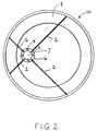
- frame 1 has members consisting of a substantially horizontal element 2 an upstanding element 3 and a downward element 4.
- Each member is constructed from a single metal rod covered with a protective coating.
- Elements 3 and 4 are formed by bending the ends of the rods in opposite direction but in the same plane.
- Elements 3 are inserted in bores 5 formed around the perimeter of collar 6 which defines a central vertical passage 7.
- the passage is shown cylindrical but it could be rectangular or have an irregular shape.
- Elements 4 are inserted in holes 8 formed on the side wall 9 of container 10.
- a container made from a firm plastic or other material is preferable but the device can also be used if the material is resilient.
- the preferred number of members is four requiring the collar to have four bores 5.
- the collar has eight circumferentially disposed bores, four can be used to retain a plant support.
- the bores could have different sizes or shapes so that different sizes or types of plant supports can be used depending on the application.
- the frame is constructed from rods having a circular cross-section the bores housing the upstanding elements must be cylindrical.
- elements 2 are shown at 90° to each other. Since elements 3 are pivoted within bores 5 the same device can be used with a larger container.
- the shorter pair of element 2, 2a, 2b are inserted in holes 8 at the same distance apart as with the smaller container but elements 2c, 2d are rotated in the direction of the arrow in order to locate the position of the required holes.
- the new position of elements 2c and 2d are shown in dotted lines. Although the angular displacement between the longer elements 2c, 2d is no longer 90° the rigidity of the assembly is maintained. As the container size is increased, the collar becomes further displaced from the centre of the container and therefore there is a limit to the increase in container size using the same size device.
- elements 3 are made a sliding fit into the bores and are bent at an angle of about 110°.
- Elements 4 are bent at an angle of about 80°.
- elements 3 are inserted into the bore and elements 4 into the appropriate holes 8.
- Provided elements 2 have been sized correctly in relation to the position of the holes, when the collar is pushed downwards as far as the bend on the member, elements 3 are pulled inwardly in the radial direction towards the centre, elements 4 press tightly against the holes and/or side walls of the container and the frame is prevented from being dislodged with movement of the plant support.
- collar 6 has to be fined to elements 3 after elements 4 have been inserted into holes 8 and cane 11 is inserted through the central passage 7 into the container 10 and into the growing medium 12 ( Figure 8). Since a cane has an irregular shape and there is no guarantee that it will fit tightly within passage 7 the length of collar 6 is made about 40mm to prevent the cane or stake from excessive tilting. Instead of one thick collar two thin ones can be used spaced about 30mm apart.
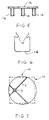
- Passage 7 is sized to receive an average size cane or stake. Smaller sizes supports can be used by inserting a tube 6a within the passage with the tube resting on the growing medium ( Figure 8). If both the centre passage and the four bores receiving elements 3 need to be downsized so that a thinner rod can be used to construct the members in the case when appropriate by the size of container, the attachment shown in figure 5 can be used.
- a thin disc having a hole 13 has tubes 14 attached to it which are inserted into the bores 5 with an interference fit. The length of tubes 14 is half that of bores 5 so that a similar attachment can be inserted from the opposite face of the collar. If it is desirable to prevent the cane or stake from entering the growing medium Figure 8 a clip made from spring wire or strip such as the one shown in Figure 6 can be used with parts 15 fitting into opposite bores and part 16 blocking the passage.
- Figure 7 shows a device constructed from a single size frame used with a round or square container.
- two devices may be required depending on the length of the container.
- Figure 8 shows different types of plant supports 11, 11a retained by the collar's central passage or bores.
Landscapes
- Life Sciences & Earth Sciences (AREA)
- Environmental Sciences (AREA)
- Cultivation Receptacles Or Flower-Pots, Or Pots For Seedlings (AREA)
Applications Claiming Priority (4)
| Application Number | Priority Date | Filing Date | Title |
|---|---|---|---|
| GB9825223 | 1998-11-19 | ||
| GBGB9825223.2A GB9825223D0 (en) | 1998-11-19 | 1998-11-19 | Device for retaining supports for plants in a container |
| GB9906938A GB2343828B (en) | 1998-11-19 | 1999-03-26 | Device for retaining supports for plants in a container |
| GB9906938 | 1999-03-26 |
Publications (2)
| Publication Number | Publication Date |
|---|---|
| EP1021945A2 true EP1021945A2 (de) | 2000-07-26 |
| EP1021945A3 EP1021945A3 (de) | 2001-05-09 |
Family
ID=26314688
Family Applications (1)
| Application Number | Title | Priority Date | Filing Date |
|---|---|---|---|
| EP99203651A Withdrawn EP1021945A3 (de) | 1998-11-19 | 1999-11-04 | Vorrichtung zur Halterung von Trägern für Pflanzen in einem Behälter |
Country Status (3)
| Country | Link |
|---|---|
| US (1) | US6302368B1 (de) |
| EP (1) | EP1021945A3 (de) |
| AU (1) | AU753231B2 (de) |
Cited By (2)
| Publication number | Priority date | Publication date | Assignee | Title |
|---|---|---|---|---|
| NL2005911C2 (nl) * | 2010-12-23 | 2012-06-27 | Jobu Plastics B V | Compacte stoksteun, alsmede matrijs voor het vervaardigen van de stoksteun. |
| ITRE20110058A1 (it) * | 2011-07-27 | 2013-01-28 | William Mazzoli | "elemento perimetrale e sistema per delimitare una superficie" |
Families Citing this family (5)
| Publication number | Priority date | Publication date | Assignee | Title |
|---|---|---|---|---|
| EP0958736A1 (de) * | 1998-05-12 | 1999-11-24 | Garden Systems in 't kort GARSY | Aufgestapelte Pflanzkübelanordnung |
| NZ505278A (en) * | 2000-06-20 | 2003-01-31 | Anthony John Harrison | Plant pots with a label attachment means |
| US6912809B2 (en) * | 2002-02-26 | 2005-07-05 | Adam Gregg Malofsky | Plant support system |
| NL1029401C2 (nl) * | 2005-07-01 | 2007-01-08 | Fred Van Zijl | Plantdrager alsmede werkwijze voor het telen van een gewas. |
| US8613159B2 (en) * | 2012-03-01 | 2013-12-24 | Donald Thompson | Plant training and removal apparatus |
Citations (1)
| Publication number | Priority date | Publication date | Assignee | Title |
|---|---|---|---|---|
| GB2307170A (en) | 1995-11-18 | 1997-05-21 | Philip Tsappi | Support for a vertical elongate member |
Family Cites Families (6)
| Publication number | Priority date | Publication date | Assignee | Title |
|---|---|---|---|---|
| US3582028A (en) * | 1968-08-16 | 1971-06-01 | John G Purdy | Tree holder |
| US3778929A (en) * | 1971-07-12 | 1973-12-18 | T Pearson | Plant grow guide |
| US4074461A (en) * | 1977-04-01 | 1978-02-21 | Abraham Hirschman | Plant support |
| US4320886A (en) * | 1980-03-06 | 1982-03-23 | Stodola George J | Christmas tree spacer |
| GB8815847D0 (en) * | 1988-07-04 | 1988-08-10 | Hutley T | Support device |
| AT400912B (de) * | 1994-07-05 | 1996-04-25 | Tomco Handelsges M B H | Pflanzstab-fixiereinrichtung |
-
1999
- 1999-11-04 EP EP99203651A patent/EP1021945A3/de not_active Withdrawn
- 1999-11-08 US US09/436,394 patent/US6302368B1/en not_active Expired - Fee Related
- 1999-11-12 AU AU59343/99A patent/AU753231B2/en not_active Ceased
Patent Citations (1)
| Publication number | Priority date | Publication date | Assignee | Title |
|---|---|---|---|---|
| GB2307170A (en) | 1995-11-18 | 1997-05-21 | Philip Tsappi | Support for a vertical elongate member |
Cited By (2)
| Publication number | Priority date | Publication date | Assignee | Title |
|---|---|---|---|---|
| NL2005911C2 (nl) * | 2010-12-23 | 2012-06-27 | Jobu Plastics B V | Compacte stoksteun, alsmede matrijs voor het vervaardigen van de stoksteun. |
| ITRE20110058A1 (it) * | 2011-07-27 | 2013-01-28 | William Mazzoli | "elemento perimetrale e sistema per delimitare una superficie" |
Also Published As
| Publication number | Publication date |
|---|---|
| EP1021945A3 (de) | 2001-05-09 |
| AU753231B2 (en) | 2002-10-10 |
| AU5934399A (en) | 2000-05-25 |
| US6302368B1 (en) | 2001-10-16 |
Similar Documents
| Publication | Publication Date | Title |
|---|---|---|
| US4881342A (en) | Plant support device and display stand therefor | |
| US10302110B2 (en) | Spring clamp for construction of plant cages and trellises | |
| US6389656B1 (en) | Clip, as well as wire/clip assembly | |
| US7774977B2 (en) | Trellis and tool system | |
| AU753231B2 (en) | Device for retaining supports for plants in a container | |
| US5263279A (en) | Prop-supporting device | |
| US5778597A (en) | Support device for potted plants and the like | |
| GB2343828A (en) | Retaining plant supports in a container | |
| JPH10502248A (ja) | プラント杭の固定装置 | |
| US7080479B2 (en) | Adjustable device for plant growing containers to support top dressings to the inside edge of the decorative container | |
| US5630293A (en) | Rhizome clip for orchid plants and the like | |
| AU2003100651A4 (en) | Vineyard netting post cap | |
| US11751703B2 (en) | Modular flower bed systems | |
| JPH089788A (ja) | 植木鉢と植木鉢用支え棒 | |
| WO1989007391A1 (en) | Supporting stake for plants | |
| GB2325693A (en) | Clip providing suspension means | |
| JP3045691B2 (ja) | 栽培容器に装着される植栽用保持具及び該植栽用保持具を用いた温室並びに該植栽用保持具を用いた日除け | |
| KR200232459Y1 (ko) | 화분대 | |
| KR102155966B1 (ko) | 농작물 지지대 | |
| JP3061636U (ja) | 園芸に用いる植物の保持具 | |
| JP2943863B1 (ja) | 植木鉢用スライド支柱 | |
| JPH04103446U (ja) | 角形プランター用つる支柱 | |
| JP3054715U (ja) | 植木鉢用の支柱の保持具 | |
| GB2201074A (en) | Plant supports | |
| JP2558670Y2 (ja) | 鉢植え植物のサポート枠 |
Legal Events
| Date | Code | Title | Description |
|---|---|---|---|
| PUAI | Public reference made under article 153(3) epc to a published international application that has entered the european phase |
Free format text: ORIGINAL CODE: 0009012 |
|
| AK | Designated contracting states |
Kind code of ref document: A2 Designated state(s): AT BE CH CY DE DK ES FI FR GB GR IE IT LI LU MC NL PT SE |
|
| AX | Request for extension of the european patent |
Free format text: AL;LT;LV;MK;RO;SI |
|
| PUAL | Search report despatched |
Free format text: ORIGINAL CODE: 0009013 |
|
| AK | Designated contracting states |
Kind code of ref document: A3 Designated state(s): AT BE CH CY DE DK ES FI FR GB GR IE IT LI LU MC NL PT SE |
|
| AX | Request for extension of the european patent |
Free format text: AL;LT;LV;MK;RO;SI |
|
| AKX | Designation fees paid | ||
| REG | Reference to a national code |
Ref country code: DE Ref legal event code: 8566 |
|
| STAA | Information on the status of an ep patent application or granted ep patent |
Free format text: STATUS: THE APPLICATION IS DEEMED TO BE WITHDRAWN |
|
| 18D | Application deemed to be withdrawn |
Effective date: 20011110 |