EP1022809B1 - Appareil électrique - Google Patents
Appareil électrique Download PDFInfo
- Publication number
- EP1022809B1 EP1022809B1 EP00100539A EP00100539A EP1022809B1 EP 1022809 B1 EP1022809 B1 EP 1022809B1 EP 00100539 A EP00100539 A EP 00100539A EP 00100539 A EP00100539 A EP 00100539A EP 1022809 B1 EP1022809 B1 EP 1022809B1
- Authority
- EP
- European Patent Office
- Prior art keywords
- electrical apparatus
- connection
- module
- busbars
- potential
- Prior art date
- Legal status (The legal status is an assumption and is not a legal conclusion. Google has not performed a legal analysis and makes no representation as to the accuracy of the status listed.)
- Expired - Lifetime
Links
- 239000000969 carrier Substances 0.000 claims abstract description 22
- 239000004020 conductor Substances 0.000 claims description 51
- 230000001681 protective effect Effects 0.000 claims description 28
- 238000013461 design Methods 0.000 claims description 8
- 239000003999 initiator Substances 0.000 claims description 6
- 230000002093 peripheral effect Effects 0.000 claims description 5
- 238000000034 method Methods 0.000 claims description 4
- 238000012544 monitoring process Methods 0.000 claims description 3
- 230000008054 signal transmission Effects 0.000 claims description 3
- 238000004891 communication Methods 0.000 claims description 2
- 230000000149 penetrating effect Effects 0.000 claims description 2
- 230000008569 process Effects 0.000 claims description 2
- 230000008878 coupling Effects 0.000 claims 1
- 238000010168 coupling process Methods 0.000 claims 1
- 238000005859 coupling reaction Methods 0.000 claims 1
- 210000001520 comb Anatomy 0.000 description 14
- 238000010276 construction Methods 0.000 description 6
- 230000008901 benefit Effects 0.000 description 5
- 238000003780 insertion Methods 0.000 description 5
- 230000037431 insertion Effects 0.000 description 5
- 230000005540 biological transmission Effects 0.000 description 4
- 238000005516 engineering process Methods 0.000 description 4
- 239000002360 explosive Substances 0.000 description 2
- 238000002347 injection Methods 0.000 description 2
- 239000007924 injection Substances 0.000 description 2
- 238000002372 labelling Methods 0.000 description 2
- 239000000463 material Substances 0.000 description 2
- 239000000203 mixture Substances 0.000 description 2
- 230000009467 reduction Effects 0.000 description 2
- 238000012546 transfer Methods 0.000 description 2
- CRCBRZBVCDKPGA-UHFFFAOYSA-N 1,2,5-trichloro-3-(2,5-dichlorophenyl)benzene Chemical compound ClC1=CC=C(Cl)C(C=2C(=C(Cl)C=C(Cl)C=2)Cl)=C1 CRCBRZBVCDKPGA-UHFFFAOYSA-N 0.000 description 1
- 230000000712 assembly Effects 0.000 description 1
- 238000000429 assembly Methods 0.000 description 1
- 230000015572 biosynthetic process Effects 0.000 description 1
- 230000008859 change Effects 0.000 description 1
- 230000009193 crawling Effects 0.000 description 1
- 238000004132 cross linking Methods 0.000 description 1
- 230000000994 depressogenic effect Effects 0.000 description 1
- 230000002349 favourable effect Effects 0.000 description 1
- 238000009413 insulation Methods 0.000 description 1
- 230000003993 interaction Effects 0.000 description 1
- 239000002184 metal Substances 0.000 description 1
- 238000012545 processing Methods 0.000 description 1
- 239000000243 solution Substances 0.000 description 1
Images


Classifications
-
- H—ELECTRICITY
- H05—ELECTRIC TECHNIQUES NOT OTHERWISE PROVIDED FOR
- H05K—PRINTED CIRCUITS; CASINGS OR CONSTRUCTIONAL DETAILS OF ELECTRIC APPARATUS; MANUFACTURE OF ASSEMBLAGES OF ELECTRICAL COMPONENTS
- H05K7/00—Constructional details common to different types of electric apparatus
- H05K7/14—Mounting supporting structure in casing or on frame or rack
- H05K7/1462—Mounting supporting structure in casing or on frame or rack for programmable logic controllers [PLC] for automation or industrial process control
- H05K7/1475—Bus assemblies for establishing communication between PLC modules
- H05K7/1478—Bus assemblies for establishing communication between PLC modules including a segmented bus
-
- H—ELECTRICITY
- H01—ELECTRIC ELEMENTS
- H01R—ELECTRICALLY-CONDUCTIVE CONNECTIONS; STRUCTURAL ASSOCIATIONS OF A PLURALITY OF MUTUALLY-INSULATED ELECTRICAL CONNECTING ELEMENTS; COUPLING DEVICES; CURRENT COLLECTORS
- H01R9/00—Structural associations of a plurality of mutually-insulated electrical connecting elements, e.g. terminal strips or terminal blocks; Terminals or binding posts mounted upon a base or in a case; Bases therefor
- H01R9/22—Bases, e.g. strip, block, panel
- H01R9/24—Terminal blocks
- H01R9/26—Clip-on terminal blocks for side-by-side rail- or strip-mounting
- H01R9/2675—Electrical interconnections between two blocks, e.g. by means of busbars
-
- H—ELECTRICITY
- H05—ELECTRIC TECHNIQUES NOT OTHERWISE PROVIDED FOR
- H05K—PRINTED CIRCUITS; CASINGS OR CONSTRUCTIONAL DETAILS OF ELECTRIC APPARATUS; MANUFACTURE OF ASSEMBLAGES OF ELECTRICAL COMPONENTS
- H05K7/00—Constructional details common to different types of electric apparatus
- H05K7/14—Mounting supporting structure in casing or on frame or rack
- H05K7/1462—Mounting supporting structure in casing or on frame or rack for programmable logic controllers [PLC] for automation or industrial process control
- H05K7/1468—Mechanical features of input/output (I/O) modules
Definitions
- the invention relates to an electrical device with a modular design for controlling and / or monitoring of technical processes and / or industrial and / or building automation, with at least one attachable to a DIN rail connection module, which is provided with several levels of terminals for connecting external conductors and a series of disc-shaped base terminal supports, wherein run within each terminal module substantially parallel to the mounting rail an internal bus conductor and a plurality of potential guides, and wherein the potential guides are preferably connected via busbars of the disc-shaped base terminal carrier and optionally via further elements with the connection levels.
- Such an electrical device is known from EP 95 113 730 A1.
- the terminal blocks are composed of functionally different terminal or module disks, wherein a distinction between protective conductor disks, feed disks, supply / signal conductor disks and Rastfußin.
- One or more terminal blocks can be connected via the internal bus conductor with a connection module for a fieldbus.
- This electrical device has proven itself. However, it is desirable to further simplify the construction of the individual terminal disk and to reduce the number of terminal disks of various types for constructing a terminal block or terminal module.
- the invention initially addresses the problem of simplifying the structure of the individual terminal disks and a general reduction in the dimensions of the system.
- the invention solves this problem in that the bus bars are distributed to the potential levels to the terminal levels on the two sides of the base terminal carrier and the busbars of each potential are guided only on one side of the base terminal support to the associated terminals, wherein the connected to a common potential to be supplied connections directly to each other to multiple connections.
- both the positive and the negative potential as well as the protective conductor potential can each be routed via only one busbar branch on one of the sides of the plastic base disks to the multiple terminals, which are then directly connected to one another in the respective connecting planes. Only the signal connections must be made to distinguish the signals of the connected devices via separate busbars from the connection levels to the electronics of the connection module.
- the invention makes use of the above-described skillful Stromschienenfihrung in particular in a modular system, which is based on the surprising - even independently considered thought - that each connection module of arbitrarily stackable and combinable with each other module discs and Module blocks is made, each of which build on the stackable base-plate supports, whereby the base-plate carriers are disk or block-like interpretable.
- the disk-wise construction is preferred in most applications.
- the respective base terminal carrier of the module disks and the module blocks each have an electronic circuit board, an electronics housing and a cover housing.
- the electronic circuit board, the electronics housing and the cover housing of the module blocks each overlap a plurality of and the cover housing, and preferably the electronic circuit board and the electronics housing of the module disks each only one of the base terminal carrier. Due to the fact that module disks and module blocks are based essentially on the same and compatible base elements, it is possible to combine and mix the block and disk structure as desired and, depending on the application, to realize a particularly inexpensive connection module structure. This solves in particular the problem that a pure block design leads to cost advantages for a larger number of terminal devices of the same design, whereas it can lead to cost disadvantages for a few - and moreover different - external devices.
- the module block in particular its base terminal carrier, consists of a lower part and disc elements mounted thereon.
- the particularly advantageous busbar guide of the invention can be realized without any problems in that the busbars for the positive and the negative potential and other bus bars are used for signal transmission in lateral recesses of the base terminal carrier, which of the Connection levels with the double or multiple connections to connection openings for receiving a device connector to the electronic circuit board and / or the edge of the electronic circuit board in the base wall of the recess of the base terminal carrier run.
- busbar for connecting the protective conductor potential guidance with the connection plane for the protective conductor potential is preferably integrally formed on the cross-bridges of the protective conductor Potentialfiihrung.
- the end portions of the busbars also FE contact
- connecting contacts for connecting further busbars or printed circuit board edges and / or if the end portions of the busbars at least on one side as punched / bent part receiving contacts for the device plug to - Or the edge of the - electronic circuit board are formed.
- connection levels can be realized in a simple manner by attaching separate or integrally formed extension busbars for bridging the potentials between the different connection levels of the base terminal carrier to the busbars.
- extension busbars are in particular each rotated by 90 ° to the respectively to be extended busbars and preferably designed to be resilient at one of its ends, wherein the resilient portions engage in openings of the respective busbars to be extended.
- the extension busbars engage with their end portions in resilient receiving bushes of each busbar to be extended.
- Another - particularly independently viewable - particularly advantageous variant of the invention is characterized in that the forwarding of the various potentials within the module blocks takes place on the one hand by the potential guides in the lower region facing the support rail area of the base terminal carrier and on the other hand between the multiple connections of a terminal level by cross-connector combs , which are provided with pins, which in to the Busbars molded resilient receiving bushes intervene.
- the cross-connector combs eliminates the need for a module block in each separate - possibly also different lengths - busbars to lead to the connection levels in each base terminal support.
- the potential feed takes place, for example, only once if the occupancy within the module block remains uniform over the entire module block.
- extension busbars can also be implemented on the module block. Preferably, these are each rotated by 90 ° and provided at their ends vertically upwards with receiving bushings for contacting the cross-connector combs.
- the 90 ° twisted extension busbars of separately insertable and / or molded on the base terminal carriers insulating the air gap of the busbars of other connection levels and crawling track side are separated.
- the PE transverse bridge is further arranged in the module blocks vertically in the lateral recesses of the base terminal carrier and has at its ends a receiving socket for contacting the cross-connector combs and a receiving socket for contacting the PE busbar.
- the cross connector combs are consistently continued in the direction of simple assembly of the module block in that the cross connector combs are inserted into the cover housing and engage when placing the cover on the juxtaposed base terminal support of the module block in the base terminal carrier and at least one contact portion of the multiple connections form.
- the potential within a terminal plane of a module block becomes long by a plurality of different ones
- Cross connection combs and extension busbars arbitrarily positionable in lateral recesses of the base terminal supports vary.
- the electronic circuit board is furthermore preferably connected to the module block via the first base terminal carrier of the module block.
- An advantageous construction of the electrical device with a system easily to be overlooked by the user results from the intended gateway with a simple housing design for connection of an external field bus, to which always first a module disc designed as a feeder plate.
- a module disc designed as a feeder plate To avoid a separate power supply of the gateway is provided that the power and voltage supply of the gateway and the connection modules via the attached to the gateway feed plate.
- the gateway is designed so that it can be coupled directly to the base terminal carrier and the internal bus conductor portion of the feed disc.
- the module system of the invention is completed by a closure plate, preferably with a retractable, separate end angle.
- a further advantageous variant of the invention is characterized in that in each case the last module disc of the connection module of the electrical device, preferably the EA module housing, provided with a connection or plug for passing the internal bus conductor and / or the potentials to another module disc same structure is, in particular for other connection modules of the electrical device without its own gateway, which are located on another mounting rail.
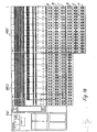
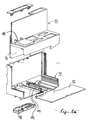
- the device G comprises a gateway GW, to which connection modules M in disk form (module disks MS) and / or block form (module blocks MB1 - MB3) are arrangeable.
- the electrical device G allows the monitoring and / or control of external electrical equipment (field devices, initiators, actuators, etc.), which can be connected to the connection modules of the electrical device according to the invention.
- the gateway GW has an electronics, not shown here and is with connecting elements SB for connecting a variety of external fieldbus systems for transfer to an internal bus conductor section 10 and with other connections / diagnostic interfaces AB (eg PS2 socket, shield, pin headers) and switch (s) SC Mistake.
- connections / diagnostic interfaces AB eg PS2 socket, shield, pin headers
- switch (s) SC Mistake eg PS2 socket, shield, pin headers) and switch (s) SC Mistake.
- connection modules M of various types, which are designed depending either on the connection of certain external electrical equipment (An gleichmodulin) or for potential injection into the system (feed module disc).
- the first adjoining the gateway module disk MS1 with the name "EI3AN” is used for feeding electrical potentials via the terminals A1, A2 to C2 in the electrical device, said potentials of the terminals A1, A2, ... via busbars and If necessary, printed conductors (not shown here) are conducted into the gateway and / or via potential guides PF, PF + into further module disks MS and / or module blocks MB.
- the second module disk MS2 (EI4AN) which, due to the larger number of connections for external conductors, allows the injection of more different electrical potentials into the system, in particular the feeding of an additional one Protective conductor potential via the fourth connection level D to the potential guide PE.
- Each of the module disks has two rows of terminals A1, B1, ..., A2, B2, etc.
- the connection levels A and possibly also D have individual connections A1, A2, D1, D2 for signal transmission to / from the externally connected devices.
- Each of the further connection levels B, C, E, F and possibly also D of the module disks MS is provided for potential forwarding with plated-through double connections (or in the block structure: multiple connections B1, B2, B3, ...), so that per module disk MS in each terminal row one or two (or more in special embodiments) external electrical equipment can be connected.
- the different number of connection levels makes it possible, depending on the type of device to be connected, to use a module disk MS with only as many connections as are absolutely necessary for the respective device.
- connection level A is used i.allg. as signal level (signal connections S).
- second connection level B is assigned a negative potential with positive-switching initiators and actuators (-).
- the positive potential +, the protective ground PE or the screen change.
- the fourth level D can serve as a signal or protective conductor connection level.
- fifth and sixth levels - again with positive switching actuators and intiators - are the negative and the positive potential or the negative potential and the protective earth. Negative switching actuators and initiators replace the negative potential with a positive potential.
- the transmission of different electrical potentials takes place from module disk to module disk.
- the minus potential, the positive potential + and the protective conductor PE are forwarded from module disk to module disk by means of the potential guides PF, PF + and PE. From these potential guides the potentials - for example, safety extra-low voltages, but also AC voltages - tapped and the connection levels B to F either directly (PE) or indirectly (PF +, PF-) supplied via an electronic circuit board (see description for Fig. 3). At the connection levels B to F, the potentials can then be tapped to supply the external electrical equipment.
- connection planes B and C (and possibly also in the connection levels D, E and F) in each case from the terminal B1 to the terminal B2 and so on.
- connection plane B If, for example, the negative potential is required in the second plane B and the positive potential is required in the third connection plane, it is thus possible to guide these two potentials on the mutually remote sides of the module disks MS to the connection planes.
- This busbar guide is extremely space and material-saving, as consuming double guides are avoided by busbars to the individual connection levels.
- the potential guidance on both sides of the module disks MS by the advantages described above also allows the space-saving extension of the busbars to further connection levels, in particular to the connection levels E and F (see also the comments on Fig. 5 and 7).
- the potential guide PE of the protective conductor is preferably directly, in particular integrally connected to the connection levels three (C) or four (D).
- the inventive electrical device G also allows the transmission of data.
- a data transmission between the gateway GW and the module disks MS and the module blocks MB Via the electronic circuit board 14 shown in FIG. 3 a, the communication between the internal bus conductor BUS and the external electrical devices takes place, the data inputs / outputs of which via the connection plane labeled "S" (in the first connection level A and / or in the fourth Connection level D) to the electronic circuit board 14 are performed.
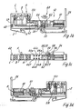
- Fig. 3a shows in conjunction with Figs. 3b to 3h different views and different elements of a module disc.
- MS which can be combined with further module disks MS and / or module blocks MB to form a connection block of variable length (FIGS. 1 and 2).
- the module disk MS has a disc-shaped base terminal carrier 2 for locking the individual module on a (not here shown) mounting rail.
- the base terminal support 2 is for this purpose provided with plastic locking feet 4, with which in known manner the locking connection to the mounting rail can be produced.
- the base terminal support 2 comprises a lower base portion 6 which extends laterally beyond the support rail in an area above the DIN rail feet 4 and adjacent to the DIN rail feet 4 on both sides.
- a bus conductor opening 8 for receiving the internal bus conductor section 10 is provided in the one remote from the mounting rail outside a base terminal support 2 perpendicular to its main plane of extent, the forwarding of the bus conductor signals from single module to individual module and in the electronic circuit board 14 allowed.
- a circumferential recess 12 is formed in the base terminal support 2.
- the electronic circuit board 14 is provided with a (not shown here) electronic circuit for processing / forwarding each guided to the electronic circuit board 14 signals.
- the base section 6 is provided with three further adjacent openings 16, 17, 18, which respectively penetrate the base terminal carrier 2 perpendicular to the main disc or module plane and two of which Openings 16, 18 with preferably one-piece transverse jumpers designed contact elements 20, 22 (on one side with a plug pin 20a, 22a, on the other with matching, integrally molded socket 20b, 22b and molded thereon contact receptacles 20c, 22c vertically upward) are provided, which allow a transfer of the associated potentials - preferably the plus or minus supply potential - from module to module.
- the contact elements 20, 22 form the potential guides PF + and PF-.
- the further opening 17 serves - like other openings not described here in the base-plate support - only the material savings.
- transverse bridges 20, 22 these potentials in the circuit board and / or a suitable separate or to the Placed on the electronic circuit board connector 24 to the terminals of the busbars SM, SP in the base terminal carrier 2 and guided over this to the terminal levels of the module disk MS.
- the recess 12 is bounded at the end facing away from the support rail end of the single module by a vertically projecting from the base portion web 26 which is provided on its side facing the support rail 4 with a slot 28 for insertion of the electronic circuit board 14 and an electronics housing 29.
- a vertically upwardly projecting terminal portion 30 is integrally formed on the base portion 6, with the six arranged in two rows of three individual (A1, A2) and double terminals B1 , B2, C1, C2 is provided. Openings 34 with a square cross section next to connection openings 32 for the connections A1, A2, B1, B2... Allow the insertion of a screwdriver for opening the spring contact elements 36 arranged in the connection section 30.
- an additional opening 38 which penetrates the basic terminal support 2 and is perpendicular to the module disk plane, is provided in the base section, in which a further contact element 40 is located, via which the protective conductor PE is passed from individual module to individual module.
- a connection to one of the connecting planes can also be established via busbars SPE (see Fig. 5f).
- busbars SPE see Fig. 5f.
- the contact elements or transverse jumpers 40 are integrally formed with the busbar SPE to the third connection level C, D.
- the conductive connection between the contact springs 36 of the terminals A, B, C, ... and the electronic circuit board 14 is realized by means of the busbars SM (for the negative potential), SP (for the positive potential), SSI (for the signal), respectively run first from the contact springs 36 in the connection region 30 of the base support bracket 2 vertically down to the base portion 6 and then in Base section 6 are led to the electronic circuit board 14.
- the busbars SM, SP extend from the contact springs 36 in lateral grooves / recesses 42 of the base element 2 substantially U-shaped on both main outer surfaces (ie with respect to the representation of Figure 3b-d on the front and the rear side) of the base Terminal carrier 2.
- busbars are angled upward and extend to the circumferential recess 12, which in this area with six in two rows adjacent terminal openings 44 for mounting the device connector 24 on the electronic circuit board and / or the PCB edge is provided.
- the end portions of the busbars SSI, SM, SP are designed as stamped bent part sockets and form even the connection sockets for the device connector 24 to the electronic circuit board 14 and / or the circuit board edge.
- a particularly space-saving arrangement of the busbars is achieved in that one of the potential-carrying busbars SM on one outer side (see Fig. 3d) and the other potential-carrying busbar SP on the other outer side (see Fig. 3b) of the base terminal carrier 2 is performed , Only in the region of the connecting springs 36, the through-connection between the two in a connection plane B or C adjacent two double terminals B1 and B2, etc. ..
- a cover housing 46 made of plastic can be placed over the connection section 30, which has openings 48 which correspond to the connection openings 32 and the openings 34.
- To the region of the recess 12 of the base terminal support 2 toward the cover is further provided with a lateral groove 50, which in cooperation with the groove 28, the electronic circuit board 14 and the electronics cradle 14 protective housing 29 receives, which in the insertion direction SR on the basis Terminal support 2 can be placed.
- Guide pins F on the base clamp support the mechanical connection of the stacked clamp supports when engaged in an associated opening of the adjacent clamp.
- PEisto provided in a particularly space-saving manner a recess 62 for a lower portion 64 of a Kodierimplantations 66 (Fig. 3a), which when placing the circuit board or the electronics from the housing 29th the electronic circuit board 14 engages in the recess 62 and thus forms the counterpart for a remaining on the electronics unit 12/29 upper coding 68.
- the circuit board 14 is arranged laterally offset parallel to the main plane HE in the housing 29 and in the recess 12 that can be applied to their PCB edge plug-in pins or sockets , These include plug elements of the internal bus conductor (not shown here) and one of the two rows of connector pins of the device connector 24 for engagement in the contact openings 44. In this way - ie by the contact on the edge of the circuit board - separate device connectors are saved, which otherwise take over the respective contact would. Also the contact the potential guides through the potential-guide contact hole 59 is made by directly on the printed circuit board 14 molded connector pins (not visible here).
- module disc MS Another advantage of the module disc MS according to the invention is that the side latching hook 56 conveniently depressed in front of the opening 57 in the area 57 'or from above through the opening 57 with a screwdriver and thus the lock to the adjacent module disc (opening 61) in the simplest and clearest Way can be solved.
- the busbar guide the individual potentials is significantly simplified only on one of the two outer sides of the module disk MS. Due to the fact that the terminals 44e and f closest to the connection plane A are utilized for signal supply to the electronic circuit board, only very short busbars SSI need to be inserted between the openings 44e, f and the connection plane A.
- the arrangement of the functional areas in the area of the electronic circuit board realizes a particularly space-saving module disk and base terminal carrier distribution.
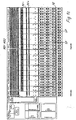
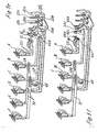
- FIG. 4 differs from that of FIG. 3 in particular in that the module disc not only three but a total of four terminal levels A, B, C, D has.
- FIG. 5 differs from that of FIG. 4 by further connecting planes E and F, wherein two possible busbar guides of this embodiment are shown in FIGS. 5e and 5f.
- the first and fourth connection planes are designed as signal connection planes leading to the openings 44a, 44b and 44e, 44f.
- the second and third and the fifth and sixth connection levels B, C and E, F are occupied by the minus and the positive potential.
- Fig. 5e also shows the FE_Stromschiene and the formation of the end portions of the busbars (SFE, SSI, SM, SP, SPE) as stamped / bent part contact receptacles 45 for connecting further busbars or printed circuit board edges.
- Fig. 5f differs from this version only in that in Fig. 5f in the third and sixth levels, ie in the levels C and F instead of the positive potential, the protective ground.
- the potential supply to the connecting planes E and F is carried out in an uncomplicated manner by an extension busbar 72, one of which is guided in the middle of the module disc and the other on one of the outer sides of the module disc 90 ° twisted to each busbars to be extended.
- the extension busbars 72 of FIGS. 5e and 5f are slotted at one of their ends, with the slotted section 74 engaging in openings 76 of the respective busbars SM or SP or SPE.
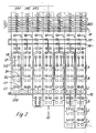
- FIG. 6 differs from the embodiments of FIGS. 3 to 5 by the connection technique used. Instead of the connection levels with screw or spring technology, the connection of the external devices by means of space-saving sensor / Aktorstecker 78, each with a clamping and / or cutting device 80 for clamping and possibly penetrating the insulation of conductors inserted into the plug 78 82 occurs (Cutting / clamping technology, crimp) is provided.
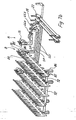
- connection module is implemented as a module block MB with six connection levels A to F.
- module block MB still has a disc-shaped structure, but it is only a single overarching electronic circuit board (not shown here) and a single overarching electronics housing 29 (not shown) and a single, several base terminal body 2 together cover housing 46 '(only exemplified with four connection levels) for the terminals of the connection levels A, B, .. used.
- the potentials PE, + and - are conducted to the connecting planes B to F only in one or both of the relative to the mounting rail end plates 2 by means of busbars SM, SP, SPE of the potential guides PE, PF + and PF-.
- cross-connector combs 84 which are provided with pins 85, which engage in integrally formed on the busbars SM, SP or SPE receiving bushes 86.
- the cross connector combs 84 are each providable with the clamping spring terminals 36 and are placed on the cover housing 46 ', through which they dive when placing the cover 46' in the base terminal carrier 2.
- a cover 89 By means of a cover 89 , the cover housing 46 'and the cross-connector combs are covered at the top.
- the busbars of the potential guides (PF, PF + and / or PE) of the module blocks (MB) consist of different lengths of busbar sections.
- the extension busbars 72 'of the module block (MB) are each oriented rotated by 90 ° and provided at their ends vertically upwards with receiving sockets 86' for contacting the pins 85 of the crossbar combs 84.
- the 90 ° twisted extension busbars 72 are preferably separated by separately insertable and / or molded on the base terminal carriers insulating from the potential of the busbar of the connection level D (air and creepage) separately (not visible here).
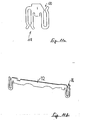
- FIG. 11 One version of a PE cross jumper 118 (see FIG. 11) is located at the module blocks MB perpendicular to the lateral recesses 42 of the base terminal carrier 2 and has at its ends at least one receiving socket (up) 120 for contacting the cross-linking combs 84 and a Bushing (downwards) for contacting the busbar SPE.
- FIGS. 1 c and 1 d and FIG. 7 b additionally illustrate that the busbars of the potential guides PF, PF + and / or PE) of the module blocks MB can consist of a single cross-section or of several busbar sections of the same length or different lengths (see, for example, FIG 1c MB1 and MB3 with respect to PF + guidance).
- module block MB can in turn be combined with other module blocks MB - but also with individual module disks MS.
- the system thus enables both the realization as a pure disc construction as well as a pure block solution or a mixture of these two forms. About a not shown here end plate, the system is completed.
- the cover housing 46 of the module blocks with grooves 87 for clear assignment of screwdriver guide, conductor introduction, colored potential marking and labeling of a connection or to delimit other connection levels and to record colored potential markings.
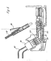
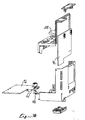
- FIG. 8 shows an illustration of a gateway housing 88 whose walls 90 are adapted to the design of the module disks MS.
- the housing is provided with a receptacle for a FE contact and PCB guides 91 for a horizontal terminal board 92 and a vertically aligned electronic circuit board 94, which is attachable to the terminal board 92.
- a receptacle is provided for a particular self-resilient foot 102.
- Housing openings 104 and 106 are provided for contacting the internal bus conductor section and the latching hook of the first module pane MS, which is lined up to the gateway.
- a protective flap 108 advantageously covers a plug connection (not otherwise shown in FIG. 9), for example for a service plug and / or a hex rotary coding switch ,
- a kind of support rod 110 which is inserted into a profile groove 112 of the lower, here horizontal wall 90.
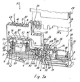
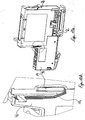
- Fig. 10 illustrates the assembled state of a base terminal support 2 together with the attached thereon cover housing 46 and electronics housing 29.
- the web 26 opposite side of the cover 46 and the electronics housing 29 are guided by two interlocking locking elements 114, 116.
- a lock is also conceivable.
- FIG. 11a shows the further PE cross-bridge 118 and FIG. 11b a further variant of an extension busbar 72 for the block build-up.
- the advantage of these variants is that the elements are simply punched out of a sheet metal strip as stamped parts, wherein the receiving bushes 86 and 120 lie in the plane of the remaining extension busbar 72 and the rest of the transverse link 118, respectively.
Landscapes
- Engineering & Computer Science (AREA)
- Automation & Control Theory (AREA)
- Microelectronics & Electronic Packaging (AREA)
- Connections Arranged To Contact A Plurality Of Conductors (AREA)
- Coupling Device And Connection With Printed Circuit (AREA)
- Multi-Conductor Connections (AREA)
- Electrical Discharge Machining, Electrochemical Machining, And Combined Machining (AREA)
- Power Steering Mechanism (AREA)
Claims (45)
- Appareil électrique à construction modulaire pour la commande et/ou la surveillance de processus techniques et/ou pour l'automatisation dans l'industrie et le bâtiment, comprenant
au moins un module de connexion (M) pouvant être monté sur une barre porteuse et qui présente plusieurs plans (A, B, C, D ...) de connexions (A1, A2, B1, ...) pour la connexion de conducteurs extérieurs et une juxtaposition de supports de bornes de base en forme de plaque (2),
dans lequel, à l'intérieur de chaque module de connexion (M), s'étendent, sensiblement parallèlement à la barre porteuse, un conducteur bus interne (BUS) ainsi que plusieurs guides de potentiel (PE ; PF+, PF-), les guides de potentiel étant reliés aux plans de connexions, de préférence par l'intermédiaire de barres conductrices des supports de bornes de base en forme de plaque (2) et éventuellement par l'intermédiaire d'autres éléments,
caractérisé en ce que
les barres conductrices (SM, SP, SPE) destinées à l'amenée de potentiel aux plans de connexions (B, C, D, ...) sont réparties sur les deux côtés du support de bornes de base (2) et les barres conductrices de chaque potentiel individuel (SM, SP, SPE) passent chacune seulement sur un des côtés du support de bornes de base (2) pour atteindre les connexions correspondantes (B1, B2, ...),
cependant que les connexions (B1, B2, ...) qui doivent être alimentées avec un potentiel commun sont reliées directement entre elles pour former des connexions multiples. - Appareil électrique selon la revendication 1, caractérisé en ce que- chaque module de connexion est composé de plaques de modules (MS) et/ou de blocs de modules (MB) qui peuvent être juxtaposés de façon arbitraire et qui peuvent être combinés entre eux, qui se montent respectivement sur les supports de bornes de base (2) pouvant être juxtaposés, lesquels sont réalisés en forme de plaques ou de blocs,- les plaques de modules (MS) et les blocs de modules (MB) présentent chacun au moins une plaquette imprimée d'électronique (14), un boîtier d'électronique (29) et un boîtier de protection (46).
- Appareil électrique selon la revendication 2, caractérisé en ce que la plaquette imprimée d'électronique (14), le boîtier d'électronique (29') et le boîtier de protection (46') des blocs de modules (MB) recouvrent chacun plusieurs supports de bornes de base (2) et le boîtier de protection (46), de même que, de préférence, la plaquette imprimée d'électronique et le boîtier d'électronique (29) des plaques de modules (MS) recouvrent de préférence chacun seulement un des supports de bornes de base (2).
- Appareil électrique selon la revendication 2, caractérisé en ce qu'à chaque fois une des plaquettes imprimées d'électronique (14) et un des boîtiers d'électronique (29) recouvrent plusieurs des plaques de modules juxtaposées (MS) et/ou en ce qu'un bloc de modules est muni de plusieurs boîtiers d'électronique (29) et/ou plaquettes imprimées d'électronique (14).
- Appareil électrique selon l'une des revendications précédentes, caractérisé en ce que les guides de potentiel (PE, PF+, PF-) sont formés par emboîtement de contacts de pontage transversaux (20, 22, 40) dans des ouvertures de passage (16, 18, 38), de préférence dans la zone inférieure des supports de bornes de base (2) qui est dirigée vers la barre porteuse.
- Appareil électrique selon l'une des revendications précédentes, caractérisé en ce que- deux des guides de potentiel (PF-, PF+) destinés à la transmission d'un potentiel positif et d'un potentiel négatif sont disposés au-dessous d'un évidement périphérique (12) destiné à loger la plaquette imprimée d'électronique (14) et le boîtier d'électronique (29, 29'), et en ce que- un autre des guides de potentiel (PE) destiné à la transmission du potentiel d'un conducteur de protection est disposé entre les troisième et quatrième plans de connexions (C, D).
- Appareil électrique selon l'une des revendications précédentes, caractérisé en ce que les barres conductrices (SM, SP) pour le potentiel positif et le potentiel négatif, ainsi que d'autres barres conductrices (SSI) destinées à la transmission de signaux, sont insérées dans des évidements latéraux (42) du support de bornes de base (2), évidements qui s'étendent depuis les plans de connexions (A1, A2, B1, B2 ... ou A1, A2, A3, ..., B1 ...) jusqu'aux ouvertures de connexions (44) destinées à recevoir un connecteur d'appareil pour le plaquette imprimée d'électronique (14) et/ou au bord du plaquette imprimée d'électronique (14) dans la paroi de fond (52) de l'évidement (12) du support de bornes de base.
- Appareil électrique selon l'une des revendications précédentes, caractérisé en ce que la barre conductrice (SPE) destinée à la liaison du guide de potentiel du conducteur de protection au plan de connexion (C, D) pour le potentiel de conducteur de protection (PE) est de préférence formée d'une seule pièce sur les contacts de pontage transversaux (40) du guide de potentiel du conducteur de protection.
- Appareil électrique selon l'une des revendications précédentes, caractérisé en ce que le potentiel positif et le potentiel négatif est transmis, par l'intermédiaire du connecteur d'appareil (24) et/ou de la plaquette imprimée d'électronique, des contacts de pontage transversaux du guide de potentiel (PF + , PF-) respectivement à une des ouvertures de connexions (44c, 44d) sur des côtés extérieurs opposés du support de bornes de base (2).
- Appareil électrique selon l'une des revendications précédentes, caractérisé en ce que les zones terminales des barres conductrices (SFE, SSI, SM, SP, SPE) sont constituées comme contacts de connexion servant à connecter d'autres barres conductrices ou bords de plaquettes imprimées.
- Appareil électrique selon l'une des revendications précédentes, caractérisé en ce que des contacts à ressorts (36, 78) sont fixés aux premières zones terminales des barres conductrices et/ou en ce que ces zones terminales sont constituées par des connexions vissées ou à broches.
- Appareil électrique selon l'une des revendications précédentes, caractérisé en ce que les zones terminales des barres conductrices sont réalisées au moins sur un côté sous la forme d'éléments femelles de contact (45) constitués par des pièces découpées/pliées, pour la fiche d'appareil, ou pour le bord de la plaquette imprimée d'électronique (14).
- Appareil électrique selon l'une des revendications précédentes, caractérisé par des barres conductrices (72) prolongatrices, attachées aux barres conductrices (SM, SP, SPE), séparées mais de préférence en une seule pièce avec elles, destinées à relier les potentiels entre les différents plans de connexions (..., B, C, ..., E, F, ..., H, I, ...) des supports de bornes de base (2).
- Appareil électrique selon l'une des revendications précédentes, caractérisé en ce que les barres conductrices (72) prolongatrices sont montées sur les barres conductrices à prolonger, chacune tordue à 90 °.
- Appareil électrique selon l'une des revendications précédentes, caractérisé en ce que les barres conductrices prolongatrices (72) sont réalisées à la façon de ressorts à l'une de leurs extrémités, les segments à ressort (74) étant engagés dans des ouvertures (76) des barres conductrices respectives à prolonger (SM, SP) et/ou en ce que les barres conductrices (72) prolongatrices sont engagées par leurs zones terminales dans des douilles réceptrices à ressort des barres conductrices (SM, SP) à prolonger respectives.
- Appareil électrique selon l'une des revendications précédentes, caractérisé en ce que la transmission des différents potentiels à l'intérieur des blocs de modules (MB) s'effectue, d'une part, par les guides de potentiel (PE, PF + , PF-) dans la zone inférieure des supports de bornes de base (2) qui est dirigée vers la barre porteuse et, d'autre part, entre les connexions multiples d'un plan de connexions (B, C, ...) par des peignes de connexion transversaux (84) qui sont munis de doigts (85) qui s'engagent dans des douilles réceptrices (86) à ressorts formées sur les barres conductrices (SM, SP, SPE) et/ou en ce que les peignes de connexion transversaux (84) sont munis de douilles à ressorts dans lesquelles s'engagent des doigts venus de formage sur les barres conductrices.
- Appareil électrique selon l'une des revendications précédentes, caractérisé en ce que les barres conductrices des guides de potentiel (PF-, PF + et/ou PE) des blocs de modules (MB) sont composées de tronçons de barres conductrices de différentes longueurs.
- Appareil électrique selon l'une des revendications précédentes, caractérisé en ce que les barres conductrices (72) prolongatrices du bloc de modules (MB) sont tordues chacune de 90 ° et présentent à leurs extrémités des douilles de réception dirigées verticalement vers le haut pour la mise en contact des peignes de connexion transversaux (84).
- Appareil électrique selon l'une des revendications précédentes, caractérisé en ce que les barres conductrices (72) prolongatrices, tordues de 90 °, sont séparées du potentiel de la barre conductrice du plan de connexions (D) (du côté de l'air ou de la ligne de fuite) par des barres isolantes qui peuvent être mises en place séparément et/ou qui sont formées par injection sur les supports de bornes de base.
- Appareil électrique selon l'une des revendications précédentes, caractérisé en ce que le contact de pontage transversal PE prévu sur les blocs de modules (MB) est disposé perpendiculairement dans les évidements latéraux (42) des supports de bornes de base (2) et il présente à ses extrémités une douille de réception pour la mise en contact du peigne de connexion transversal (84) et une douille de réception dirigée vers le bas pour la mise en contact de la barre conductrice (SPE).
- Appareil électrique selon l'une des revendications précédentes, caractérisé en ce que les peignes de connexion transversaux (84) sont embrochés dans le boîtier de protection (46') et, lors de la pose du boîtier de protection sur les supports de bornes de base juxtaposés (2) du bloc de modules (MB), ils s'engagent dans les supports de bornes de base (2) et forment à chaque fois au moins un segment de contact des connexions multiples (B, C, ...).
- Appareil électrique selon l'une des revendications précédentes, caractérisé en ce que, dans le cas d'initiateurs/actionneurs à commutation positive, les différents plans de connexions présentent l'occupation suivante :- premier plan de connexions (A) : premier plan de signaux ;- deuxième plan de connexions (B) : potentiel négatif ;- troisième plan de connexions (C) : potentiel positif ou terre de protection ou blindage ;
et (s'ils sont présents) :- quatrième plan de connexions (D) : terre de protection ou deuxième plan de signaux ;- cinquième plan de connexions (E) : potentiel négatif ;- sixième plan de connexions (F) ; potentiel positif ou terre de protection ;et, dans le cas d'initiateurs/actionneurs à commutation négative, les plans de connexions conduisant le potentiel positif et le potentiel négatif présentent des occupations inversées. - Appareil électrique selon l'une des revendications précédentes, caractérisé en ce que le potentiel à l'intérieur du plan de connexions d'un bloc de module (MB) varie sous l'effet de différences de longueur des peignes de connexion transversaux (84) et des barres conductrices (72) prolongatrices qui peuvent être positionnées arbitrairement dans des évidements latéraux (42) des supports de bornes de base (2).
- Appareil électrique selon l'une des revendications précédentes, caractérisé en ce que la plaque de module (MS) présente, dans la zone de l'évidement périphérique (12) pour la plaquette imprimée d'électronique (14) en allant de l'extérieur vers la barre porteuse, les zones fonctionnelles suivantes :- bus de module (ouverture) (8),- canal de repérage (54),- crochet d'encliquetage latéral (56),- contact de FE (terre de fonction) (58),- ouverture de guide de potentiel - mise en contact (59), et- connexions (44) pour le raccordement des barres conductrices avec un connecteur sur la plaquette imprimée d'électronique et/ou directement avec la plaquette imprimée (14).
- Appareil électrique selon l'une des revendications précédentes, caractérisé en ce que les connexions (44) sur les plans de connexions présentent l'occupation suivante :- barres conductrices et de signaux (SSI) en partant du quatrième plan de connexions (D) (connexions 44a, b) ;- barres conductrices positives-négatives vers les connexions multiples (B1, B2, C1, C2) (connexions 44c, d) ;- deux fois les barres conductrices et de signaux (SSI) en partant du premier plan de connexions (A) (connexions 44e, f).
- Appareil électrique selon l'une des revendications précédentes, caractérisé en ce que, dans la zone de l'évidement périphérique (12), il est prévu un évidement (62) pour un élément encodeur (66) en supplément du contact FE (58) et de l'ouverture de guide de potentiel-mise en contact (59).
- Appareil électrique selon l'une des revendications précédentes, caractérisé en ce que le contact FE (58) est réalisé en une seule pièce et est mis directement en contact avec le bord de la plaquette imprimée d'électronique (14) par sa zone terminale.
- Appareil électrique selon l'une des revendications précédentes, caractérisé en ce que des broches de connexion de mise en contact sont formées sur le bord de la plaquette imprimée (14).
- Appareil électrique selon l'une des revendications précédentes, caractérisé en ce qu'il est prévu dans l'évidement périphérique (12) au moins une ouverture (57', 57) pour la plaquette imprimée d'électronique (14), ouverture à travers laquelle un crochet d'encliquetage (56) qui émerge latéralement du support de bornes de base (2) de la borne voisine peut être déverrouillé avec un outil (tournevis).
- Appareil électrique selon l'une des revendications précédentes, caractérisé en ce que le support de bornes de base (2), lorsqu'il est réalisé avec quatre plans de connexions (A, B, ...), est pourvu d'un canal de répartition transversale (70) qui se trouve au-dessous du quatrième plan de connexions (D), pour transmettre un potentiel électrique, en particulier pour le pontage individuel de racines de relais par des connecteurs transversaux embrochables.
- Appareil électrique selon l'une des revendications précédentes, caractérisé en ce que le support de bornes de base (2) est muni, dans sa zone extérieure qui est éloignée de la barre porteuse, d'une ouverture de conducteur bus (8) qui traverse le support de bornes de base (2) perpendiculairement à son plan d'extension principal, pour recevoir le tronçon interne (10) du conducteur bus.
- Appareil électrique selon l'une des revendications précédentes, caractérisé en ce qu'aussi bien sur les supports de bornes de base (2) des plaques de modules (MS) que sur les supports de bornes de base (2) frontaux des blocs de modules (MB), peuvent être embrochés, à chaque fois le tronçon interne (10) du conducteur bus, les guides de potentiel (PF+, PF- et PE) ainsi que des éléments d'accouplement mécanique tels que le crochet d'encliquetage (56).
- Appareil électrique selon l'une des revendications précédentes, caractérisé en ce que la plaquette imprimée d'électronique du bloc de modules (MB), avec le bloc de modules (MB), sont connectés pour la communication et l'alimentation, de préférence par l'intermédiaire du premier support de bornes de base du bloc de module (MB).
- Appareil électrique selon l'une des revendications précédentes, caractérisé par une interface (GW) pour la connexion d'un bus de champ auquel fait suite une plaque d'alimentation constituée par une plaque de module (MS).
- Appareil électrique selon l'une des revendications précédentes, caractérisé en ce que l'alimentation en courant et en tension de l'interface (GW) et des modules de connexion (M) s'effectue par l'intermédiaire de la plaque d'alimentation (MS) juxtaposée à l'interface (GW).
- Appareil électrique selon l'une des revendications précédentes, caractérisé en ce que l'interface (GW) présente une structure en bottier, sensiblement en deux parties, qui possède deux guides de plaquette imprimée décalés de 90°.
- Appareil électrique selon l'une des revendications précédentes, caractérisé en ce que l'interface (GW) peut être directement accouplée aux supports de bornes (2) et au tronçon de conducteur bus interne (10) des blocs ou plaques de modules (MB, MS).
- Appareil électrique selon l'une des revendications précédentes, caractérisé par une plaque de fermeture munie d'une équerre terminale séparée, pouvant être emmanchée.
- Appareil électrique selon l'une des revendications précédentes, caractérisé en ce que la dernière plaque de module (MS) est munie d'une connexion ou d'un connecteur, constitué de préférence par son boîtier de module EA, qui sert pour la prolongation du tronçon de conducteur bus interne (10) ou des potentiels (PF-, PF +) vers une autre plaque de module ou à un bloc de modules de même construction, en particulier pour d'autres modules de connexion (M) de l'appareil électrique sans interface propre, qui se trouvent sur une autre barre porteuse.
- Appareil électrique selon l'une des revendications précédentes, caractérisé en ce que les boîtiers de protection (46, 46') situés entre les plans de connexions sont munis de rainures pour créer une correspondance visible de guides de tournevis, d'insertion de conducteurs, de marquages de potentiels colorés et de l'inscription d'une connexion, ou encore pour délimiter d'autres plans de connexions et pour recevoir des marquages de potentiels colorés.
- Appareil électrique selon l'une des revendications précédentes, caractérisé en ce que les barres conductrices conduisant des signaux sont constituées au moins partiellement par des guides optiques.
- Appareil électrique selon l'une des revendications précédentes, caractérisé en ce que le boîtier de protection (46) et le boîtier d'électronique (29) sont guidés et/ou verrouillés l'un contre l'autre au moyen d'éléments (114, 116) qui s'engagent les uns dans les autres.
- Appareil électrique selon l'une des revendications précédentes, caractérisé en ce que plusieurs des supports de bornes de base (2) et/ou plusieurs des capots de connexions et/ou d'électronique (46, 29) d'une construction en forme de plaque, à la façon d'une unité pré-montée, peuvent être assemblés en un unique bloc recouvrant de modules (MB) avant l'encliquetage sur la barre porteuse.
- Appareil électrique selon l'une des revendications précédentes, caractérisé en ce qu'au moins une des parois (90) du boîtier d'interface (88) peut être stabilisée au moyen d'une barre de support (110).
- Appareil électrique selon l'une des revendications précédentes, caractérisé en ce que le bloc de modules (MB), en particulier son support de bornes de base (2), est composé d'une partie inférieure continue et d'éléments en plaques montés sur cette dernière.
Applications Claiming Priority (2)
| Application Number | Priority Date | Filing Date | Title |
|---|---|---|---|
| DE1999102745 DE19902745B4 (de) | 1999-01-25 | 1999-01-25 | Elektrisches Gerät |
| DE19902745 | 1999-01-25 |
Publications (3)
| Publication Number | Publication Date |
|---|---|
| EP1022809A2 EP1022809A2 (fr) | 2000-07-26 |
| EP1022809A3 EP1022809A3 (fr) | 2001-06-27 |
| EP1022809B1 true EP1022809B1 (fr) | 2006-04-05 |
Family
ID=7895248
Family Applications (1)
| Application Number | Title | Priority Date | Filing Date |
|---|---|---|---|
| EP00100539A Expired - Lifetime EP1022809B1 (fr) | 1999-01-25 | 2000-01-12 | Appareil électrique |
Country Status (5)
| Country | Link |
|---|---|
| US (1) | US6392319B1 (fr) |
| EP (1) | EP1022809B1 (fr) |
| AT (1) | ATE322751T1 (fr) |
| DE (3) | DE19964156B4 (fr) |
| ES (1) | ES2259580T3 (fr) |
Families Citing this family (44)
| Publication number | Priority date | Publication date | Assignee | Title |
|---|---|---|---|---|
| US6572403B2 (en) | 2001-01-22 | 2003-06-03 | National Instruments Corporation | Expansion plug apparatus for connecting a plurality of terminal blocks |
| DE50203656D1 (de) * | 2001-05-16 | 2005-08-25 | Gustav Hensel Gmbh & Co Kg | Schaltgerätesystem |
| DE10146503A1 (de) * | 2001-09-21 | 2003-04-10 | Abb Patent Gmbh | Elektrische Installationsverteilung |
| DE20211002U1 (de) * | 2002-07-19 | 2003-12-04 | Weidmüller Interface Gmbh & Co. | Modul für ein elektrisches Gerät, insbesondere Feldbusmodul |
| DE10249981B3 (de) * | 2002-10-26 | 2004-04-01 | Moeller Gmbh | Elektronische Steuereinrichtung mit Mitteln zur Ableitung von Störsignalen |
| DE20306768U1 (de) * | 2003-05-02 | 2004-09-02 | Weidmüller Interface Gmbh & Co. | Elektrisches Gerät mit mehreren Schneid-/Klemmanschlußvorrichtungen |
| GB0312414D0 (en) * | 2003-05-30 | 2003-07-02 | Fortress Interlocks Ltd | Security or safety bus system |
| US7101231B2 (en) * | 2003-10-09 | 2006-09-05 | Cooper Technologies Company | Locking spring-clamp terminal block and method for connecting the same |
| DE20315838U1 (de) * | 2003-10-15 | 2005-02-24 | Weidmüller Interface GmbH & Co. KG | Verteiler zum Anschluß elektrischer Geräte mit Leuchteinrichtung |
| DE10361344A1 (de) * | 2003-12-18 | 2005-07-14 | Valeo Schalter Und Sensoren Gmbh | Schaltermodul |
| EP1564848B1 (fr) | 2004-02-16 | 2013-10-16 | Siemens Aktiengesellschaft | Dispositif d'installation avec interface enfichable codable et module supplémentaire correspondant |
| DE102004043466B4 (de) * | 2004-09-08 | 2007-08-02 | Siemens Ag | Strom-Einspeisemodul mit Käfig-Zugfederklemmen |
| DE202005013056U1 (de) * | 2005-08-18 | 2007-01-04 | Weidmüller Interface GmbH & Co. KG | Elektrische Anschlussvorrichtung |
| DE102005040657A1 (de) * | 2005-08-26 | 2007-03-15 | Phoenix Contact Gmbh & Co. Kg | Elektrische Anschlussklemme |
| US7524214B2 (en) * | 2005-12-27 | 2009-04-28 | The Boeing Company | Electrical quick lock interconnect |
| DE202006017882U1 (de) * | 2006-11-22 | 2007-03-01 | Cedes Ag | Steckmodul |
| DE102007059640B4 (de) * | 2007-12-10 | 2009-11-26 | Wago Verwaltungsgesellschaft Mbh | Anschlussmodul |
| DE102008008716A1 (de) * | 2008-02-11 | 2009-08-13 | Weidmüller Interface GmbH & Co. KG | Elektronikgehäuse mit einer Leiterplatte und Verfahren zur Herstellung eines Elektronikgehäuses |
| DE202008002113U1 (de) * | 2008-02-14 | 2009-06-25 | Weidmüller Interface GmbH & Co. KG | Anreihbares Elektronikgehäuse |
| DE102008014177A1 (de) * | 2008-03-14 | 2009-09-17 | Phoenix Contact Gmbh & Co. Kg | Reihenklemme und Reihenklemmblock |
| EP2128942B1 (fr) * | 2008-05-28 | 2011-11-23 | EATON Industries Manufacturing GmbH | Système de bus modulaire et corps de module correspondant |
| GB2467552A (en) * | 2009-02-04 | 2010-08-11 | Eltek Valere As | Rail mounted power supply |
| US8066239B2 (en) * | 2009-06-15 | 2011-11-29 | Rockwell Automation Technologies, Inc. | Integrated DIN rail attachment feature for superior attachment |
| DE202010004408U1 (de) | 2009-12-10 | 2011-04-21 | Weidmüller Interface GmbH & Co. KG | Reihung von Anschlussmodulen |
| DE202011000686U1 (de) | 2010-03-31 | 2012-01-13 | Weidmüller Interface GmbH & Co. KG | Busfähiges Anschlussmodul |
| DE202010005979U1 (de) | 2010-04-22 | 2011-08-26 | Weidmüller Interface GmbH & Co. KG | Busfähiges, anreihbares Anschlussmodul |
| DE202010006140U1 (de) | 2010-04-28 | 2011-09-07 | Weidmüller Interface GmbH & Co. KG | Busfähiges Anschlussmodul |
| DE202011000834U1 (de) | 2010-06-29 | 2011-11-08 | Weidmüller Interface GmbH & Co. KG | Busfähiges Anschluss- und/oder Funktionsmodul und Anschlusssystem mit derartigen Modulen |
| DE202010010275U1 (de) | 2010-07-15 | 2011-12-20 | Weidmüller Interface GmbH & Co. KG | Elektrisches Kontaktteil |
| DE102011051154A1 (de) | 2010-08-02 | 2012-02-02 | Weidmüller Interface GmbH & Co. KG | Busfähiges Anschluss- und/oder Funktionsmodul und Anschlusssystem mit derartigen Modulen |
| CN102170751A (zh) * | 2011-02-24 | 2011-08-31 | 华为技术有限公司 | 单板及通信设备 |
| AT13096U1 (de) | 2011-10-17 | 2013-06-15 | Tridonic Connection Technology Gmbh & Co Kg | Vorrichtung zum kontaktieren von elektrischen leitern und/oder elektrischen kontaktelementen, sowie leuchte oder elektrisches gerät |
| US8715017B1 (en) * | 2012-02-08 | 2014-05-06 | Phoenix Contact Development and Manufacturing, Inc. | Terminal block having an extender body fitted to a contact body |
| US9336977B1 (en) | 2015-04-03 | 2016-05-10 | Eaton Corporation | Electrical switching apparatus and secondary disconnect assembly with terminal retention and correction features therefor |
| US9576762B2 (en) | 2015-04-03 | 2017-02-21 | Eaton Corporation | Electrical switching apparatus and secondary disconnect assembly with error-proofing features therefor |
| US9570261B2 (en) | 2015-04-03 | 2017-02-14 | Eaton Corporation | Electrical switching apparatus and secondary disconnect assembly with contact alignment features therefor |
| US9396889B1 (en) * | 2015-04-03 | 2016-07-19 | Eaton Corporation | Electrical switching apparatus and secondary disconnect assembly with cradle assembly alignment and positioning features therefor |
| DE102015221899B3 (de) * | 2015-11-06 | 2016-12-22 | Ellenberger & Poensgen Gmbh | Stromverteiler |
| GB2547946B (en) * | 2016-03-04 | 2020-05-20 | Ge Aviat Systems Ltd | Method and apparatus for modular power distribution |
| DE202016101995U1 (de) * | 2016-04-15 | 2017-07-18 | Ptr Messtechnik Gmbh | Vorrichtung zur elektrisch leitenden Verbindung einer Elektronikeinheit mit einer Tragschiene sowie elektronisches Gerät mit einer Elektronikeinheit und einer solchen Vorrichtung |
| JP6321760B1 (ja) * | 2016-11-16 | 2018-05-09 | ファナック株式会社 | 接続部材およびそれを具備するモータ駆動装置 |
| JP6950672B2 (ja) * | 2018-12-26 | 2021-10-13 | オムロン株式会社 | 端子台 |
| DE102020125076A1 (de) * | 2020-09-25 | 2022-03-31 | Weidmüller Interface GmbH & Co. KG | Funktionsmodul zur Steuerung und/oder Überwachung technischer Prozesse |
| US20240356260A1 (en) * | 2021-07-27 | 2024-10-24 | Honeywell International Inc. | Hot swap base for a building controller |
Family Cites Families (24)
| Publication number | Priority date | Publication date | Assignee | Title |
|---|---|---|---|---|
| DE58908455D1 (de) * | 1989-05-12 | 1994-11-03 | Weidmueller Interface | Reihenklemmenanordnung. |
| US5037310A (en) * | 1989-12-06 | 1991-08-06 | Gespac, Inc. | Connector apparatus and method for distributed control modules used in computer networks |
| DE4303717C2 (de) * | 1993-02-09 | 1996-02-08 | Phoenix Contact Gmbh & Co | Modul zum Anschluß elektrischer Leitungen und zur Verarbeitung und/oder Bearbeitung elektrischer Signale |
| DE4402001B4 (de) * | 1994-01-18 | 2007-02-22 | Wago Verwaltungsgesellschaft Mbh | E/A-Modul für einen Datenbus |
| DE4410171C1 (de) * | 1994-03-24 | 1995-04-13 | Licentia Gmbh | Baugruppe eines Automatisierungsgeräts |
| FR2718543B1 (fr) * | 1994-04-08 | 1996-06-21 | Robot Consult Sa | Système et dispositif de pré-automatisation des installations d'un bâtiment. |
| DE4438800C1 (de) * | 1994-10-31 | 1996-01-18 | Weidmueller Interface | Anschlußklemmenblock mit Elektronikmodul |
| DE4438806C1 (de) * | 1994-10-31 | 1996-03-21 | Weidmueller Interface | Modulare Steuerungsanlage mit Busleiter |
| DE4438804C1 (de) * | 1994-10-31 | 1996-03-28 | Weidmueller Interface | Modulare Steuerungsanlage mit Busleiter z. B. zur Gebäudeautomatisierung |
| DE4438805C1 (de) * | 1994-10-31 | 1996-03-07 | Weidmueller Interface | Feldbusanschlußmodul |
| DE4438803C1 (de) * | 1994-10-31 | 1996-03-21 | Weidmueller Interface | Verteilerleisten mit Querverteilung der elektrischen Leistung (I) |
| DE4440102C1 (de) * | 1994-11-10 | 1996-05-15 | Weidmueller Interface | Modulare Steuerungsanlage mit integriertem Feldbusanschluß |
| DE29502186U1 (de) * | 1995-02-10 | 1995-03-30 | Weidmüller Interface GmbH & Co, 32760 Detmold | Elektrische Verteileranordnung |
| FR2732518B1 (fr) * | 1995-03-29 | 1997-04-30 | Entrelec Sa | Agencement de connexion pour fils conducteurs electriques et module, notamment de type bloc de jonction, equipe d'un tel agencement |
| US6033257A (en) * | 1995-11-20 | 2000-03-07 | The Foxboro Company | I/O connector module for a field controller in a distributed control system |
| DE29611543U1 (de) | 1996-07-04 | 1996-09-05 | Phoenix Contact Gmbh & Co., 32825 Blomberg | Reihenklemmenblock |
| US5775955A (en) * | 1996-09-17 | 1998-07-07 | Graube; Maris | Modular fieldbus terminal block |
| FR2757316B1 (fr) * | 1996-12-16 | 1999-01-22 | Entrelec Sa | Module de raccordement a bornes de connexion interconnectables par piece(s) conductrice(s) mobile(s) |
| DE19734709C1 (de) * | 1997-08-11 | 1998-11-12 | Siemens Ag | Schaltgerätesystem mit modular aufgebautem Energiebus |
| DE19748531A1 (de) * | 1997-11-03 | 1999-05-06 | Siemens Ag | Aufbausystem für Verbraucherabzweige mit stehender Verdrahtung |
| US6191948B1 (en) * | 1998-01-29 | 2001-02-20 | Ellenberger & Poensgen Gmbh | Power supply device |
| DE29804284U1 (de) * | 1998-03-11 | 1998-05-07 | Weidmüller Interface GmbH & Co, 32760 Detmold | Steuerungsanlage für elektronische Steuerungs- und Automatisierungssysteme |
| US6146213A (en) * | 1998-12-10 | 2000-11-14 | Yoon; Heung-Sik | Wire connection with exchangeable securing member for electric connection terminal assembly |
| DE29901194U1 (de) * | 1999-01-25 | 1999-05-20 | Weidmüller Interface GmbH & Co., 32760 Detmold | Busleiterabschnitt für ein elektrisches Gerät |
-
1999
- 1999-01-25 DE DE19964156A patent/DE19964156B4/de not_active Expired - Lifetime
- 1999-01-25 DE DE19964157A patent/DE19964157A1/de not_active Withdrawn
-
2000
- 2000-01-12 ES ES00100539T patent/ES2259580T3/es not_active Expired - Lifetime
- 2000-01-12 EP EP00100539A patent/EP1022809B1/fr not_active Expired - Lifetime
- 2000-01-12 DE DE50012503T patent/DE50012503D1/de not_active Expired - Lifetime
- 2000-01-12 AT AT00100539T patent/ATE322751T1/de active
- 2000-01-24 US US09/490,699 patent/US6392319B1/en not_active Expired - Lifetime
Also Published As
| Publication number | Publication date |
|---|---|
| DE19964156A1 (de) | 2000-09-07 |
| ATE322751T1 (de) | 2006-04-15 |
| DE19964156B4 (de) | 2004-07-15 |
| DE50012503D1 (de) | 2006-05-18 |
| ES2259580T3 (es) | 2006-10-16 |
| EP1022809A3 (fr) | 2001-06-27 |
| EP1022809A2 (fr) | 2000-07-26 |
| US6392319B1 (en) | 2002-05-21 |
| DE19964157A1 (de) | 2000-10-05 |
Similar Documents
| Publication | Publication Date | Title |
|---|---|---|
| EP1022809B1 (fr) | Appareil électrique | |
| DE19902745B4 (de) | Elektrisches Gerät | |
| DE4005049C2 (de) | Elektrischer Verteiler | |
| EP0123822B1 (fr) | Connecteur transversal pour bornes alignées | |
| EP1022934B1 (fr) | Tronçon de bus pour appareil électrique | |
| EP2491622B1 (fr) | Système destiné à relier des conducteurs électriques ayant des potentiels différents, ainsi qu'adaptateur enfichable pour le système | |
| DE3843664C2 (fr) | ||
| EP3111515B1 (fr) | Barrette à bornes et bloc de barrettes à bornes | |
| DE102008050322B4 (de) | Elektromotor-Anschluss sowie Elektromotor | |
| EP0709932A2 (fr) | Installation de réglage avec bus, par example pour l'automation d'édifice | |
| DE60212232T2 (de) | Verbinderdose | |
| DE19964150A1 (de) | Kodiervorrichtung zur Kodierung eines elektrischen Gerätes | |
| EP0709919A1 (fr) | Barrette d'interconnexion pour repartition transversale de puissance | |
| DE102006031129B4 (de) | Gerätesystem mit auf einer Tragschiene montierten elektrischen Gerätemodulen und in der Tragschine angeordneter BUS-Leitung | |
| DE102007048710B4 (de) | Elektrischer Querverbinder | |
| EP1734551B1 (fr) | Dispositif à enfichage pour dispositif électrique de coupure | |
| EP0739060B1 (fr) | Connecteur à broche | |
| EP0813269B1 (fr) | Connecteur électrique | |
| EP0222030A1 (fr) | Bloc de connexion pour initiateur | |
| DE10351479B4 (de) | Gerätesystem mit auf einer Tragschiene montierten elektrischen Geräten und BUS-Leitung | |
| EP1085605B1 (fr) | Tronçon de bus pour appareil électrique | |
| DE3442056A1 (de) | Steckverbindervorrichtung | |
| EP1432076B1 (fr) | Barette à bornes électrique | |
| WO2020099552A1 (fr) | Dispositif de connexion pour conducteurs électriques | |
| DE10146503A1 (de) | Elektrische Installationsverteilung |
Legal Events
| Date | Code | Title | Description |
|---|---|---|---|
| PUAI | Public reference made under article 153(3) epc to a published international application that has entered the european phase |
Free format text: ORIGINAL CODE: 0009012 |
|
| AK | Designated contracting states |
Kind code of ref document: A2 Designated state(s): AT BE CH CY DE DK ES FI FR GB GR IE IT LI LU MC NL PT SE |
|
| AX | Request for extension of the european patent |
Free format text: AL;LT;LV;MK;RO;SI |
|
| PUAL | Search report despatched |
Free format text: ORIGINAL CODE: 0009013 |
|
| AK | Designated contracting states |
Kind code of ref document: A3 Designated state(s): AT BE CH CY DE DK ES FI FR GB GR IE IT LI LU MC NL PT SE |
|
| AX | Request for extension of the european patent |
Free format text: AL;LT;LV;MK;RO;SI |
|
| RIC1 | Information provided on ipc code assigned before grant |
Free format text: 7H 01R 9/26 A, 7H 02B 1/20 B, 7H 05K 7/14 B |
|
| 17P | Request for examination filed |
Effective date: 20010620 |
|
| AKX | Designation fees paid |
Free format text: AT BE CH CY DE DK ES FI FR GB GR IE IT LI LU MC NL PT SE |
|
| GRAP | Despatch of communication of intention to grant a patent |
Free format text: ORIGINAL CODE: EPIDOSNIGR1 |
|
| GRAS | Grant fee paid |
Free format text: ORIGINAL CODE: EPIDOSNIGR3 |
|
| GRAA | (expected) grant |
Free format text: ORIGINAL CODE: 0009210 |
|
| AK | Designated contracting states |
Kind code of ref document: B1 Designated state(s): AT BE CH CY DE DK ES FI FR GB GR IE IT LI LU MC NL PT SE |
|
| PG25 | Lapsed in a contracting state [announced via postgrant information from national office to epo] |
Ref country code: IT Free format text: LAPSE BECAUSE OF FAILURE TO SUBMIT A TRANSLATION OF THE DESCRIPTION OR TO PAY THE FEE WITHIN THE PRESCRIBED TIME-LIMIT;WARNING: LAPSES OF ITALIAN PATENTS WITH EFFECTIVE DATE BEFORE 2007 MAY HAVE OCCURRED AT ANY TIME BEFORE 2007. THE CORRECT EFFECTIVE DATE MAY BE DIFFERENT FROM THE ONE RECORDED. Effective date: 20060405 Ref country code: IE Free format text: LAPSE BECAUSE OF FAILURE TO SUBMIT A TRANSLATION OF THE DESCRIPTION OR TO PAY THE FEE WITHIN THE PRESCRIBED TIME-LIMIT Effective date: 20060405 |
|
| REG | Reference to a national code |
Ref country code: GB Ref legal event code: FG4D Free format text: NOT ENGLISH |
|
| REG | Reference to a national code |
Ref country code: CH Ref legal event code: EP |
|
| REG | Reference to a national code |
Ref country code: CH Ref legal event code: NV Representative=s name: ISLER & PEDRAZZINI AG |
|
| REG | Reference to a national code |
Ref country code: IE Ref legal event code: FG4D Free format text: LANGUAGE OF EP DOCUMENT: GERMAN |
|
| REF | Corresponds to: |
Ref document number: 50012503 Country of ref document: DE Date of ref document: 20060518 Kind code of ref document: P |
|
| PG25 | Lapsed in a contracting state [announced via postgrant information from national office to epo] |
Ref country code: SE Free format text: LAPSE BECAUSE OF FAILURE TO SUBMIT A TRANSLATION OF THE DESCRIPTION OR TO PAY THE FEE WITHIN THE PRESCRIBED TIME-LIMIT Effective date: 20060705 Ref country code: DK Free format text: LAPSE BECAUSE OF FAILURE TO SUBMIT A TRANSLATION OF THE DESCRIPTION OR TO PAY THE FEE WITHIN THE PRESCRIBED TIME-LIMIT Effective date: 20060705 |
|
| GBT | Gb: translation of ep patent filed (gb section 77(6)(a)/1977) |
Effective date: 20060619 |
|
| PG25 | Lapsed in a contracting state [announced via postgrant information from national office to epo] |
Ref country code: PT Free format text: LAPSE BECAUSE OF FAILURE TO SUBMIT A TRANSLATION OF THE DESCRIPTION OR TO PAY THE FEE WITHIN THE PRESCRIBED TIME-LIMIT Effective date: 20060905 |
|
| REG | Reference to a national code |
Ref country code: ES Ref legal event code: FG2A Ref document number: 2259580 Country of ref document: ES Kind code of ref document: T3 |
|
| REG | Reference to a national code |
Ref country code: IE Ref legal event code: FD4D |
|
| ET | Fr: translation filed | ||
| PG25 | Lapsed in a contracting state [announced via postgrant information from national office to epo] |
Ref country code: MC Free format text: LAPSE BECAUSE OF NON-PAYMENT OF DUE FEES Effective date: 20070131 |
|
| PLBE | No opposition filed within time limit |
Free format text: ORIGINAL CODE: 0009261 |
|
| STAA | Information on the status of an ep patent application or granted ep patent |
Free format text: STATUS: NO OPPOSITION FILED WITHIN TIME LIMIT |
|
| 26N | No opposition filed |
Effective date: 20070108 |
|
| REG | Reference to a national code |
Ref country code: CH Ref legal event code: PCAR Free format text: ISLER & PEDRAZZINI AG;POSTFACH 1772;8027 ZUERICH (CH) |
|
| BERE | Be: lapsed |
Owner name: WEIDMULLER INTERFACE G.M.B.H. & CO. Effective date: 20070131 |
|
| PG25 | Lapsed in a contracting state [announced via postgrant information from national office to epo] |
Ref country code: BE Free format text: LAPSE BECAUSE OF NON-PAYMENT OF DUE FEES Effective date: 20070131 |
|
| PG25 | Lapsed in a contracting state [announced via postgrant information from national office to epo] |
Ref country code: GR Free format text: LAPSE BECAUSE OF FAILURE TO SUBMIT A TRANSLATION OF THE DESCRIPTION OR TO PAY THE FEE WITHIN THE PRESCRIBED TIME-LIMIT Effective date: 20060706 |
|
| PG25 | Lapsed in a contracting state [announced via postgrant information from national office to epo] |
Ref country code: LU Free format text: LAPSE BECAUSE OF NON-PAYMENT OF DUE FEES Effective date: 20070112 Ref country code: CY Free format text: LAPSE BECAUSE OF FAILURE TO SUBMIT A TRANSLATION OF THE DESCRIPTION OR TO PAY THE FEE WITHIN THE PRESCRIBED TIME-LIMIT Effective date: 20060405 |
|
| PGFP | Annual fee paid to national office [announced via postgrant information from national office to epo] |
Ref country code: FI Payment date: 20130111 Year of fee payment: 14 |
|
| PGFP | Annual fee paid to national office [announced via postgrant information from national office to epo] |
Ref country code: AT Payment date: 20130111 Year of fee payment: 14 |
|
| PGFP | Annual fee paid to national office [announced via postgrant information from national office to epo] |
Ref country code: NL Payment date: 20140121 Year of fee payment: 15 Ref country code: CH Payment date: 20140121 Year of fee payment: 15 |
|
| PGFP | Annual fee paid to national office [announced via postgrant information from national office to epo] |
Ref country code: ES Payment date: 20140129 Year of fee payment: 15 |
|
| REG | Reference to a national code |
Ref country code: AT Ref legal event code: MM01 Ref document number: 322751 Country of ref document: AT Kind code of ref document: T Effective date: 20140112 |
|
| PG25 | Lapsed in a contracting state [announced via postgrant information from national office to epo] |
Ref country code: FI Free format text: LAPSE BECAUSE OF NON-PAYMENT OF DUE FEES Effective date: 20140112 |
|
| PG25 | Lapsed in a contracting state [announced via postgrant information from national office to epo] |
Ref country code: AT Free format text: LAPSE BECAUSE OF NON-PAYMENT OF DUE FEES Effective date: 20140112 |
|
| REG | Reference to a national code |
Ref country code: NL Ref legal event code: V1 Effective date: 20150801 |
|
| REG | Reference to a national code |
Ref country code: CH Ref legal event code: PL |
|
| PG25 | Lapsed in a contracting state [announced via postgrant information from national office to epo] |
Ref country code: NL Free format text: LAPSE BECAUSE OF NON-PAYMENT OF DUE FEES Effective date: 20150801 |
|
| PG25 | Lapsed in a contracting state [announced via postgrant information from national office to epo] |
Ref country code: CH Free format text: LAPSE BECAUSE OF NON-PAYMENT OF DUE FEES Effective date: 20150131 Ref country code: LI Free format text: LAPSE BECAUSE OF NON-PAYMENT OF DUE FEES Effective date: 20150131 |
|
| REG | Reference to a national code |
Ref country code: FR Ref legal event code: PLFP Year of fee payment: 17 |
|
| REG | Reference to a national code |
Ref country code: ES Ref legal event code: FD2A Effective date: 20160226 |
|
| PG25 | Lapsed in a contracting state [announced via postgrant information from national office to epo] |
Ref country code: ES Free format text: LAPSE BECAUSE OF NON-PAYMENT OF DUE FEES Effective date: 20150113 |
|
| REG | Reference to a national code |
Ref country code: FR Ref legal event code: PLFP Year of fee payment: 18 |
|
| REG | Reference to a national code |
Ref country code: FR Ref legal event code: PLFP Year of fee payment: 19 |
|
| PGFP | Annual fee paid to national office [announced via postgrant information from national office to epo] |
Ref country code: DE Payment date: 20180122 Year of fee payment: 19 Ref country code: GB Payment date: 20180119 Year of fee payment: 19 |
|
| PGFP | Annual fee paid to national office [announced via postgrant information from national office to epo] |
Ref country code: IT Payment date: 20180129 Year of fee payment: 19 Ref country code: FR Payment date: 20180119 Year of fee payment: 19 |
|
| REG | Reference to a national code |
Ref country code: DE Ref legal event code: R119 Ref document number: 50012503 Country of ref document: DE |
|
| GBPC | Gb: european patent ceased through non-payment of renewal fee |
Effective date: 20190112 |
|
| PG25 | Lapsed in a contracting state [announced via postgrant information from national office to epo] |
Ref country code: DE Free format text: LAPSE BECAUSE OF NON-PAYMENT OF DUE FEES Effective date: 20190801 |
|
| PG25 | Lapsed in a contracting state [announced via postgrant information from national office to epo] |
Ref country code: GB Free format text: LAPSE BECAUSE OF NON-PAYMENT OF DUE FEES Effective date: 20190112 |
|
| PG25 | Lapsed in a contracting state [announced via postgrant information from national office to epo] |
Ref country code: IT Free format text: LAPSE BECAUSE OF NON-PAYMENT OF DUE FEES Effective date: 20190112 Ref country code: FR Free format text: LAPSE BECAUSE OF NON-PAYMENT OF DUE FEES Effective date: 20190131 |