EP1022912B1 - Bildaufnahmegerät - Google Patents
Bildaufnahmegerät Download PDFInfo
- Publication number
- EP1022912B1 EP1022912B1 EP00300408A EP00300408A EP1022912B1 EP 1022912 B1 EP1022912 B1 EP 1022912B1 EP 00300408 A EP00300408 A EP 00300408A EP 00300408 A EP00300408 A EP 00300408A EP 1022912 B1 EP1022912 B1 EP 1022912B1
- Authority
- EP
- European Patent Office
- Prior art keywords
- color
- pseudo
- image
- data
- hue
- Prior art date
- Legal status (The legal status is an assumption and is not a legal conclusion. Google has not performed a legal analysis and makes no representation as to the accuracy of the status listed.)
- Expired - Lifetime
Links
- 238000006243 chemical reaction Methods 0.000 claims description 14
- 238000000926 separation method Methods 0.000 claims 2
- 230000001419 dependent effect Effects 0.000 claims 1
- 238000000605 extraction Methods 0.000 claims 1
- 239000003086 colorant Substances 0.000 description 74
- 238000012545 processing Methods 0.000 description 58
- 230000000052 comparative effect Effects 0.000 description 54
- 238000001444 catalytic combustion detection Methods 0.000 description 46
- 238000001914 filtration Methods 0.000 description 32
- 230000006835 compression Effects 0.000 description 30
- 238000007906 compression Methods 0.000 description 30
- 238000010276 construction Methods 0.000 description 28
- 238000010586 diagram Methods 0.000 description 24
- 230000003287 optical effect Effects 0.000 description 16
- 238000000034 method Methods 0.000 description 15
- 230000001629 suppression Effects 0.000 description 15
- 238000009499 grossing Methods 0.000 description 13
- 238000001514 detection method Methods 0.000 description 11
- 230000002093 peripheral effect Effects 0.000 description 11
- 230000000873 masking effect Effects 0.000 description 10
- 230000008569 process Effects 0.000 description 8
- 230000006870 function Effects 0.000 description 7
- 230000009467 reduction Effects 0.000 description 6
- 230000012447 hatching Effects 0.000 description 5
- 230000008859 change Effects 0.000 description 4
- 238000004042 decolorization Methods 0.000 description 4
- 230000001174 ascending effect Effects 0.000 description 3
- 230000007423 decrease Effects 0.000 description 3
- 230000000694 effects Effects 0.000 description 3
- 239000011159 matrix material Substances 0.000 description 3
- 238000007796 conventional method Methods 0.000 description 2
- 230000003111 delayed effect Effects 0.000 description 2
- 239000011521 glass Substances 0.000 description 2
- 229910021607 Silver chloride Inorganic materials 0.000 description 1
- 238000012937 correction Methods 0.000 description 1
- 230000003247 decreasing effect Effects 0.000 description 1
- 230000009977 dual effect Effects 0.000 description 1
- 238000003708 edge detection Methods 0.000 description 1
- 238000012986 modification Methods 0.000 description 1
- 230000004048 modification Effects 0.000 description 1
- 238000003672 processing method Methods 0.000 description 1
- 230000005855 radiation Effects 0.000 description 1
- HKZLPVFGJNLROG-UHFFFAOYSA-M silver monochloride Chemical compound [Cl-].[Ag+] HKZLPVFGJNLROG-UHFFFAOYSA-M 0.000 description 1
- 239000010409 thin film Substances 0.000 description 1
Images








Classifications
-
- H—ELECTRICITY
- H04—ELECTRIC COMMUNICATION TECHNIQUE
- H04N—PICTORIAL COMMUNICATION, e.g. TELEVISION
- H04N23/00—Cameras or camera modules comprising electronic image sensors; Control thereof
- H04N23/80—Camera processing pipelines; Components thereof
- H04N23/84—Camera processing pipelines; Components thereof for processing colour signals
- H04N23/843—Demosaicing, e.g. interpolating colour pixel values
-
- H—ELECTRICITY
- H04—ELECTRIC COMMUNICATION TECHNIQUE
- H04N—PICTORIAL COMMUNICATION, e.g. TELEVISION
- H04N2209/00—Details of colour television systems
- H04N2209/04—Picture signal generators
- H04N2209/041—Picture signal generators using solid-state devices
- H04N2209/042—Picture signal generators using solid-state devices having a single pick-up sensor
- H04N2209/045—Picture signal generators using solid-state devices having a single pick-up sensor using mosaic colour filter
- H04N2209/046—Colour interpolation to calculate the missing colour values
Definitions
- the present invention relates to an image sensing apparatus such as a digital camera or digital video camera or the like, and an image processing method for the image sensing apparatus.
- a conventional single-plate color digital camera is a lens-integrated system ,and is generally incapable of exchanging a lens.
- an optical low pass filter and infrared ray (IR) filter or the like are provided before a CCD, which generates image signals according to light passing through the lens, thereby achieving a certain degree of effectiveness in reducing moiré or pseudo colors (erroneous colors).
- an IR filter can be provided before a CCD by forming a thin film on a glass surface of the CCD.
- securing space for an optical low pass filter before a CCD causes to increase the size of the camera body.
- optical low pass filter can reduce moiré or pseudo colors to a certain degree, a problem arises in that spatial frequency of an image decreases, and as a result, the image loses exact-focused characteristic such as that obtained in silver chloride photographs. Because of the above reason, the importance of an optical system without an optical low pass filter is increasing.
- red (R) and yellow (Y) vertical stripes are obtained (in Fig. 19 , hatching portion indicates black where data is 0).
- Fig. 20 if vertical white lines are exposed to green (G) and blue (B) lines of a CCD at pixel pitch and color interpolation is performed, blue (B) and cyan (C) vertical stripes are obtained. Note that even if the stripes in Figs. 19 and 20 are horizontal instead of vertical, the same results, i.e., red (R) and yellow (Y) stripes or blue (B) and cyan (C) stripes, are obtained.
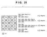
- a magenta (M) image is obtained despite the original white color.
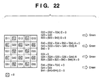
- a green (G) image is obtained despite the original white color.
- the color space is converted from RGB to, for instance, L*a*b* and filtering is performed on each of the a* and b* color spaces by an application program operating in a personal computer.
- a low frequency image of green cannot be distinguished from that of magenta, making it impossible to determine pseudo colors.
- the frequency band of color difference is forcefully limited for JPEG compression, a dull (blurred) image is obtained.
- the level of pseudo colors is reduced, the pseudo color components are spread out to the peripheral pixels, causing problems.
- a color camera includes an image detector for detecting radiation in sampled channels and a channel reconstructor coupled to an output of the detector.
- the reconstructor includes a luminance generator which combines the sampled channels to a luminance channel, a gradient generator coupled to an output of the luminance generator and which transfers the luminance channel to a gradient channel, and a directional interpolator coupled to an output of the detector and to an output of the gradient generator and which transfers each of the sampled channels to a corresponding reconstructed channel, and a reconstructed channel output.
- Document WO 97/34423 discloses an electronic still camera and a method associated therewith, which is useful with a sensor of rectangular pixel geometry.
- Dual resolution modes for producing square pixels for display are provided. In one resolution mode, neighboring pairs of pixels are averaged in the direction normal to the major axis of the rectangular pixels within each color plane such that one half as many square pixel RGB triplets are formed as there were original single color rectangular pixels, while in the second resolution mode new RGB triplets are interjected by interpolation in the direction parallel to the major axis of the rectangular pixels such that twice as many square pixel RGB triplets are formed as there were original single color rectangular pixels.
- a method of compression for stored images is also provided.
- Document JP 4120993 discloses a color temperature detection circuit which discriminates whether or not a color temperature of an object is a color temperature at which no false color signal is caused, and when the color temperature is a color temperature at which no false color signal is caused, the suppression of a color signal by a color signal suppression circuit is limited by using a vertical edge detection signal obtained by a vertical contour correction circuit and an adder circuit. Thus, complete disregard of color information by suppressing the color signal even when no false color signal is in existence, can be prevented and the color reproducibility is enhanced.
- the present invention is made in consideration of the above situation, and has as a concern to provide an image sensing apparatus capable of reducing pseudo colors generated by color interpolation.
- Another concern of the present invention is to provide an image sensing apparatus which can reduce pseudo colors without increasing the size or cost of the image sensing apparatus.
- Another concern of the present invention is to provide an image sensing apparatus which can reduce pseudo colors with relatively a simple construction.
- Another concern of the present invention is to provide an image sensing apparatus which can reduce pseudo colors in isolated pixels with relatively a simple construction.
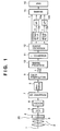
- Fig. 1 is a block diagram showing, mainly, a construction of an image processing unit of a digital camera according to a first comparative example of the present invention.
- a CCD image sensing device 5
- an optical low pass filter 20 limits a spatial frequency of the light 1 to reduce moiré in a way that an optical area of a long wavelength is cut off by an infrared ray (IR) filter 4 so that the CCD 5 does not detect light in the infrared region.
- IR infrared ray
- the amount of electric charge is amplified by a predetermined gain by a CDS ⁇ AGC 6, and converted to digital data by an A/D converter 7.
- Image data converted to digital data in the foregoing manner is transferred to a white balance circuit 8 where R, G and B gains are adjusted.
- a color interpolator 9 the image data is generated in, for instance, three color (R, G and B) planes.
- the image data expressed in the R, G and B planes are then transferred to a masking processor 10 where adjustment is made for the hue of the R, G and B colors.
- a gamma converter 11 performs necessary processing for displaying an image on a display or the like.
- an RGB/YUV converter 12 converts the image data from R, G and B signals to Y color difference signals.
- a pseudo color generated by color interpolation is reduced by median filters 13a and 13b.
- Low pass filters (LPF) 14a and 14b remove high frequency components to limit the band.
- a compression circuit 16 adopting JPEG or the like performs compression.
- Figs. 2A and 2B explain the principle of processing performed by the median filters 13a and 13b according to the first (and subsequent) comparative example.
- Fig. 2A shows 3 ⁇ 3 pixels peripheral to a pixel of interest
- Fig. 2B shows a graph of pixel values arranged in the ascending order.
- a color space of an inputted image signal is converted from RGB to YUV color space, and an isolated pixel is removed from color difference signals U and V of the YUV signal by the median filter or the like.
- pseudo color removal is performed by a median filter, after a color space of input image data is converted from RGB color space to Y, R-Y, B-Y color space.
- Fig. 3 is a block diagram showing a construction of an image processing unit of a digital camera according to the second comparative example.
- the second comparative example largely differs from the foregoing first comparative example in that the second comparative example does not necessitate JPEG compression and that the YUV conversion can be eliminated since the pseudo-color-removed image data is stored in a memory 19. Therefore, the construction of the image processing unit can be made simple, which contributes to the effect of the second comparative example. This is also applicable to a case of performing compression according to JPEG or the like.
- image data is converted from RGB color space to Y, R-Y, B-Y color space by, for instance, using a Y, R-Y, B-Y converter 17a.
- the median filters 17b and 17c respectively executes median filtering of the R-Y signal and B-Y signal.
- R-Ye and B-Ye are calculated with a luminance signal Ye which is a simplified (approximate) form of the luminance signal Y.
- a luminance signal Ye which is a simplified (approximate) form of the luminance signal Y.
- an RGB converter 17d respectively converts the Y, R-Y and B-Y signals back to R, G and B signals.
- the image data represented by R, G and B signals is subjected to masking by a masking processor 10 and to a gamma conversion by a gamma converter 11, and then stored in the non-volatile memory 19.
- the luminance signal Y is consciously calculated from R, G and B signals.
- G signal of the R, G and B may substitute for the luminance signal Y.
- the third comparative example is characterized by employing G, R-G and B-G signals instead of Y, R-Y and B-Y signals employed in the second comparative example and executing median filtering to R-G and B-G signals respectively.
- Fig. 4 is a block diagram showing a construction of an image processing unit of a digital camera according to the third comparative example of the present invention.
- the same reference numerals are assigned and description thereof will be omitted.
- the amount of calculation is reduced further when compared against the case of converting R, G and B signals to luminance signal Y and color difference signals R-Y and B-Y.
- the median filters 18b and 18c respectively execute filtering to the R-G and B-G signals, thereby removing pseudo colors generated by color interpolation. Then, the RGB converter 18d converts the G, R-G and B-G signals back to RGB signals, which are then subjected to the masking processor 10 and gamma converter 11, and then stored in the non-volatile memory 19.
- the third comparative example employs G signal in place of luminance signal Y, pseudo color reduction can be realized with a less amount of calculation, although there is a possibility that luminance components of the RGB signals may be influenced by the result of median filtering.
- the fourth comparative example describes a case where no problem arises even though the optical system does not comprise such optical low pass filter.
- Fig. 5 is a block diagram showing a construction of an image processing unit of a digital camera according to the fourth comparative example of the present invention.
- the fourth comparative example is characterized in that the IR filter 4 for cutting infrared rays is provided before the CCD 5, and that the optical low pass filter 20 employed in Fig. 1 is removed.
- the configuration after the CCD 5 is the same as that shown in block diagram of Fig. 1 .
- the optical low pass filter 20 when the optical low pass filter 20 is removed, pseudo colors are generated more than the case of including the optical low pass filter 20.
- the number of elements in median filters 130a and 130b in the fourth comparative example is increased from the number of elements "9" of the median filters according to first to third comparative examples. By this, the median filtering can be executed in a wider area, and pseudo colors can be reduced.
- the apparatus main body can be made small and cost reduction can be achieved.
- image signals of high resolution can be obtained.
- weight coefficient Fi min ⁇ i / ⁇ i where an average value of each block is ⁇ i, distribution is ⁇ i, and m (arbitrary)
- filtering called hysteresis smoothing may be employed. More specifically, a hysteresis characteristic is produced for a data value, and noise is absorbed by the hysteresis characteristic. Any of the aforementioned filters may be used as long as interpolation or smoothing is performed by using outputs of peripheral pixels of an isolated point having a pixel value largely different from peripheral pixel values.
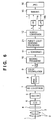
- Fig. 6 is a block diagram showing, mainly, a construction of an image processing unit of a digital camera according to the fifth comparative example of the present invention.
- the same reference numerals are assigned.
- the amount of electric charge is amplified by a predetermined gain by the CDS ⁇ AGC 6, and converted to digital data by the A/D converter 7.
- Image data converted to digital data in the foregoing manner is transferred to the white balance circuit 8 where R, G and B gains are adjusted.
- the color interpolator 9 the image data is generated in, for instance, three color (R, G and B) planes.
- the image data expressed in the R, G and B planes are then transferred to the masking processor 10 where adjustment is made for the hue of the R, G and B colors.
- the gamma converter 11 performs necessary processing for displaying an image on a display or the like.
- a pseudo color removing processor 21 reduces pseudo colors generated by color interpolation of the color interpolator 9. Further, compression processing according to JPEG or the like is performed on the image data since the data in the R, G and B color planes has a large amount of data.
- the RGB/YUV converter 12 converts the image data from R, G and B signals to Y color difference signal, and with respect to each of the color difference signals U and V, the LPF 14a and 14b respectively perform low pass filtering to limit the band.
- a JPEG compression circuit 16 performs compression according to JPEG.
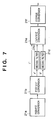
- Fig. 7 is a block diagram showing a configuration of the pseudo color removing processor 21 according to the fifth comparative example.
- RGB/XYZ converter 21a converts image data from RGB color space to XYZ color space.
- XYZ/L*a*b* converter 21b converts the image data from XYZ color space to L*a*b* color space.
- the conversion is executed by the following equations (16) to (18):
- L * 116 Y / Y 0 1 / 3 - 16 Y / Y 0 > 0.008856
- a * 500 X / X 0 1 / 3 - Y - Y 0 1 / 3
- b * 200 Y / Y 0 1 / 3 - Z - Z 0 1 / 3
- X 0 , Y 0 and Z 0 represent tristimulus values of the perfect diffuse surface.
- median filters 21c and 21d each serving as an isolated point filter, execute median filtering (median value filtering) respectively to a* and b* of the L*a*b*.
- L*a*b*/XYZ converter 21e converts image data from L*a*b* color space to XYZ color space.
- XYZ/RGB converter 21f converts the image data from XYZ color space to RGB color space.
- Fig. 8 is a block diagram showing a configuration according to the sixth comparative example of the present invention.
- image data in RGB color space which has been outputted by the pseudo color removing processor 21, is converted from RGB color space to YUV color space by the RGB/YUV converter 12 to be subjected to JPEG compression.
- This YUV conversion is executed by the aforementioned equations (1) to (3).
- filtering called smoothing Edge Preserving Smoothing
- median filter For the isolated point removing filter, filtering called smoothing (Edge Preserving Smoothing) for preserving edges, which has been described in the fourth comparative example, may be employed besides the above-described median filter.
- smoothing Maximum Homogeneity Smoothing
- smoothing for preserving edges, which has been described in the fourth comparative example, may be employed.
- filtering called hysteresis smoothing may be employed. More specifically, a hysteresis characteristic is produced for a data value, and noise is absorbed by the hysteresis characteristic. Any of the aforementioned filters may be used as long as interpolation or smoothing is performed by using outputs of peripheral pixels of an isolated point having a pixel value largely different from peripheral pixel values.
- a characteristic feature of the first embodiment is described before explaining a specific example of the first embodiment.
- To eliminate the above-described pseudo colors it is ideal to employ three-plate camera where CCDs are provided for each of the R, G and B color components. With such structure, the size of a camera increases.
- an attention is directed to the fact that pseudo colors generated from red (R) to yellow (Y) and from blue (B) to cyan (C) have high frequencies.
- the characteristic feature of the first embodiment is to suppress generation of pseudo colors by reducing the gain of a color difference signal when the luminance signal has a high frequency component and the hue falls within a predetermined range.
- Fig. 9 is a block diagram showing, mainly, a construction of an image processing unit of a digital camera according to the first embodiment of the present invention.
- a CCD image sensing device 5
- the image sensing device 5 e.g., CCD or CMOS
- a shutter not shown
- the light incident upon the CCD 5 is accumulated in the CCD 5 as an electric charge, and outputted as an electric signal.
- the electric signal is amplified by a predetermined gain by the CDS ⁇ AGC 6, and converted to digital data by the A/D converter 7.
- Image data converted to digital data in the foregoing manner is transferred to the white balance circuit 8 where R, G and B gains are adjusted.
- the color interpolator 9 the image data is generated in, for instance, three color (R, G and B) planes as shown in Fig 10 .
- the image data expressed in the R, G and B planes are then transferred to the masking processor 10 where adjustment is made for the hue of the R, G and B colors.
- the gamma converter 11 performs necessary processing for displaying an image on a display or the like. Further, compression processing according to JPEG or the like is performed on the image data since the data in the R, G and B color.planes has a large amount of data.
- RGB/Y converter 22 converts RGB color space to color space of Y color difference signal.
- the conversion is executed by, for instance, above-mentioned equations (1) to (3).
- a spatial high pass filter (HPF) 23 executes spatial high pass filter computation as shown in Fig. 11 .
- the luminance signal Y, obtained by the RGB/Y converter 22, is transferred to a hue detection circuit 24 for detecting a hue, where color difference signals R-Y and B-Y are calculated and a hue is detected based on the calculated results.
- the detected hue data is outputted to a pseudo color suppression circuit 13.
- spatial high pass filter computation is executed by multiplying an input signal by a matrix 300, and subtracting the input signal from the multiplication result by a subtractor 301.
- the pseudo color suppression circuit 13 suppresses pseudo colors by reducing gains of U and V, outputted by the RGB/Y converter 22, based on the high frequency component of the luminance signal Y obtained by the spatial high pass filter 23 and the hue data obtained by the hue detection circuit 24.
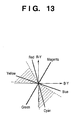
- a color of the pixel of interest falls within a predetermined range (area indicated by hatching in Fig. 13 ) in Y, R-Y, B-Y color space. If the color is determined to be in the range where it is considered as a pseudo color, gains of the color difference signals U and V, having a predetermine value of 1 or larger as shown in Fig. 12 , are reduced in accordance with a high frequency component value of the luminance signal outputted by the spatial high pass filter 23. By this, pseudo colors can be suppressed.
- a high frequency component such as that having a vertical stripe pattern or a checker flag pattern described with reference to Figs. 19 to 22 , is extracted by the spatial HPF 23.
- the aforementioned pseudo color generation is prevented by reducing gains of color difference signals U and V in the extracted high frequency area, which may cause pseudo colors described in Figs. 19 to 22 (for instance, predetermined areas of R and Y components in Fig. 19 , predetermined areas of C and B components in Fig. 20 , or predetermined areas of R and B components in Figs. 21 and 22 , all of which correspond to the hatching portion in Fig. 13 ).
- the low pass filter (LPF) 14 execute low pass filtering in the horizontal or vertical direction.
- the JPEG compression circuit 16 performs JPEG compression. By this, a compressed image having less pseudo colors can be generated.
- the calculation may be executed with a simplified luminance signal Ye.
- Ye R + 2 ⁇ G + B, may be used.
- a green (G) signal component may be used as a luminance signal without calculating the luminance signal.
- Fig. 14 is a flowchart explaining pseudo color removing processing according to the first embodiment of the present invention.
- step S1 R, G and B signals of an image, upon which color interpolation processing has been performed, are inputted and a luminance signal Y is generated from the R, G and B signals by the RGB/Y converter 22.
- step S2 high frequency components of the luminance signal Y are extracted by the spatial high pass filter (HPF) 23.
- step S3 differences are respectively calculated between each of R, B signals and the luminance signal Y by the hue detection circuit 24, and color difference signals R-Y and B-Y are generated.
- step S4 a hue signal is generated based on the color difference signals, and it is determined whether or not the hue signal falls within a color range that is considered as pseudo colors.
- step S5 If it is determined as a pseudo color in step S5, the control proceeds to step S6 where gains of the color difference signals in the pseudo color portion are reduced in accordance with the amount of high frequency component of the pixel. By this, for instance, in the color space corresponding to the hatching area in Fig. 13 , pseudo color components generated by color interpolation can be suppressed. Then the process proceeds to step S7, isolated pixels of the image are removed.
- the first embodiment achieves an effect of preventing pseudo colors generation from red to yellow and from blue to cyan.
- a characteristic feature of the second embodiment is described before explaining a specific example of the second embodiment.
- an attention is directed to the fact that pseudo colors generated from red (R) to yellow (Y) and from blue (B) to cyan (C) have high frequencies.
- the characteristic feature of the second embodiment is to suppress generation of pseudo colors by removing an isolated point of a luminance signal, having a high frequency component and, if the hue falls within a predetermined range, reducing the gain of the color difference signal.
- Fig. 15 is a block diagram showing, mainly, a construction of an image processing unit of a digital camera according to the second embodiment of the present invention.
- the pseudo color suppression circuit 13 suppresses pseudo colors by reducing gains of U and V, outputted by the RGB/YUV converter 12, based on a high frequency component of the luminance signal Y obtained by the spatial high pass filter 23 and hue data obtained by the hue detection circuit 24.
- the pseudo color suppression processing is performed in the same manner as that of the above-described first embodiment.
- patterns of pseudo colors from red (R) to yellow (Y) and from blue (B) to cyan (C) can be determined as pseudo colors by detecting high frequency components of the luminance signal because the degree of luminance of pseudo colors are different from others.
- pseudo colors generated around a character are often isolated, and the degree of luminance of the pseudo colors are not always different from the peripheral pixel luminance.
- the median filters 24a and 24b remove isolated points with respect to the color difference signals U and V and further perform pseudo color removal.
- Figs. 2A and 2B explain this processing.
- elements having 3 ⁇ 3 pixel area including a pixel of interest are arranged in the ascending order, and the value of the pixel of interest is replaced with a median value of the arranged pixels.
- a pixel, having a color of extremely different hue from the hues of peripheral pixels can be eliminated.
- resolution does not decrease largely, thus does not influence peripheral pixels.
- a high frequency component such as that having a vertical stripe pattern or a checker flag pattern described with reference to Figs. 19 to 22 , is extracted by the spatial HPF 23.
- the aforementioned pseudo color generation is prevented by reducing gains of color difference signals U and V in the extracted high frequency area, which may cause the pseudo colors described in Figs. 19 to 22 (for instance, predetermined areas of R and Y components in Fig. 19 , predetermined areas of C and B components in Fig. 20 , or predetermined areas of R and B components in Figs. 21 and 22 , all of which correspond to the hatching portion in Fig. 13 ).
- the median filters 24a and 24b execute above-described filtering, thereby removing isolated pixels.
- the low pass filter (LPF) 14a and 14b execute low pass filtering in the horizontal or vertical direction.
- the JPEG compression circuit 16 performs JPEG compression. By this, a compressed image having less pseudo colors can be generated.
- a green (G) signal component may be used as a luminance signal without calculating the luminance signal.
- means for detecting pseudo colors is provided after the color interpolator 9 and pseudo color detection is performed using signals in the R, G and B planes.
- the reason is that, since processing such as masking processing, y conversion and so forth that may cause changes in hue are performed after the color interpolator 9, the hue range of the detected pseudo colors may change. Because of this reason, the luminance signal Y is calculated to obtain color difference signals R-Y and B-Y.
- the pseudo color detection means does not have to be provided in this position. For instance, in order to perform JPEG compression, RGB color space must be converted to a color space of luminance or color difference. Therefore, pseudo colors can be detected from these signals.
- the third embodiment relates to such case. Note that, as mentioned above, there is a possibility that the hue range of pseudo colors changes depending on images.
- Fig. 16 is a block diagram showing a construction of an image processing unit of a digital camera according to the third embodiment of the present invention.
- the same reference numerals are assigned.
- the image data is generated in, for instance, three color (R, G and B) planes as shown in Fig. 10 .
- the image data expressed in the R, G and B planes are then transferred to the masking processor 10 where adjustment is made for the hue of the R, G and B colors.
- the gamma converter 11 performs necessary processing for displaying an image on a display or the like.
- RGB/YUV converter 12 converts the image data from RGB color space to color space of Y color difference signal.
- luminance signal Y is transmitted to the spatial high pass filter (HPF) 25 for detecting high frequency components of the signal by the filtering shown in Fig. 11 .
- HPF spatial high pass filter
- a hue detection circuit 26 determines whether or not a pixel of interest falls within the hue range of pseudo colors.
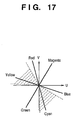
- U and V outputted by the RGB/YUV converter 12 are used as shown in Fig. 17 .
- the pseudo color suppression circuit 13 reduces gains of the color difference signals U and V, having a value of1 or larger as shown in Fig. 12 , in accordance with an output value of the spatial HPF 25.
- the hue range it may be necessary to change, for instance, the hue range depending on the white balance. For instance, when the gain of red is increased, the hue range is shifted towards red, or a hue angle is widened.
- the LPF 14a and 14b execute low pass filtering in the horizontal or vertical direction.
- the JPEG compression circuit 16 performs JPEG compression.
- means for detecting pseudo colors is provided after the color interpolator 9 and pseudo color detection is performed using signals in the R, G and B planes.
- the reason is that, since processing such as masking processing, y conversion and so forth that may cause changes in hue are performed after the color interpolator 9, the hue range of the detected pseudo colors may change. Because of this reason, the luminance signal Y is calculated to obtain color difference signals R-Y and B-Y.
- the pseudo color detection means does not have to be provided in this position. For instance, in order to perform JPEG compression, RGB color space must be converted to a color space of luminance and color difference. Therefore, pseudo colors can be detected from these signals.
- the median filters 24a and 24b where pseudo color suppression is performed delay is generated between the luminance signal Y and color difference signals U and V. Because of this, the luminance signal must also be delayed.
- the fourth embodiment makes use of this delay.
- Fig. 18 is a block diagram showing a construction of an image processing unit of a digital camera according to the fourth embodiment of the present invention.
- the same reference numerals are assigned.
- the image data is generated in, for instance, three color (R, G and B) planes as shown in Fig. 10 .
- the image data expressed in the R, G and B planes are then transferred to the masking processor 10 where adjustment is made for the hue of the R, G and B colors.
- the gamma converter 11 performs necessary processing for displaying an image on a display or the like.
- RGB/YUV converter 12 converts the image data from RGB color space to color space of Y color difference signal.
- luminance signal Y is transmitted to the spatial high pass filter (HPF) 25 for detecting high frequency components of the luminance signal by the filtering shown in Fig. 11 .
- color difference signals U and V are transmitted to the median filters 24a and 24b for executing the above-described median filtering shown in Figs. 2A and 2B .
- the hue detection circuit 26 determines whether or not a pixel of interest falls within the hue range of pseudo colors.
- U and V outputted by the RGB/YUV converter 12 are used as shown in Fig. 17 .
- the pseudo color suppression circuit 13 reduces gains of the color difference signals U and V, having a value of1 or larger as shown in Fig. 12 , in accordance with an output value of the spatial HPF 25.
- the hue range it may be necessary to change, for instance, the hue range depending on the white balance. For instance, when the gain of red is increased, the hue range is shifted to the red, or a hue angle is widened.
- the LPF 14a and 14b execute low pass filtering in the horizontal or vertical direction.
- the JPEG compression circuit 16 performs JPEG compression.
- the present invention can be applied to a system constituted by a plurality of devices (e.g., host computer, interface, reader, printer) or to an apparatus comprising a single device (e.g., copying machine, facsimile machine).
- devices e.g., host computer, interface, reader, printer
- apparatus comprising a single device (e.g., copying machine, facsimile machine).
- the object of the present invention can also be achieved by providing a storage medium storing program codes for performing the aforesaid processes to a computer system or apparatus (e.g., a personal computer), reading the program codes, by a computer (CPU or MPU) of the system or apparatus, from the storage medium, then executing the program.
- a computer system or apparatus e.g., a personal computer
- CPU or MPU central processing unit
- the program codes read from the storage medium realize the functions according to the embodiments, and the storage medium storing the program codes constitutes the invention.
- the storage medium such as a floppy disk, a hard disk, an optical disk, a magneto-optical disk, CD-ROM, CD-R, a magnetic tape, a non-volatile type memory card, and ROM can be used for providing the program codes.
- the present invention includes a case where an OS (operating system) or the like working on the computer performs a part or the entire processes in accordance with designations of the program codes and realizes functions according to the above embodiments.
- the present invention also includes a case where, after the program codes read from the storage medium are written in a function expansion card which is inserted into the computer or in a memory provided in a function expansion unit which is connected to the computer, CPU or the like contained in the function expansion card or unit performs a part or the entire process in accordance with designations of the program codes and realizes functions of the above embodiments.
- RGB color space is converted to YUV or Y, R-Y, B-Y or G, R-G, B-G color space, and isolated point removing filtering (e.g., median filter or the like) is executed respectively to color difference signals in UV, or R-Y, B-Y or R-G, B-G color space, thereby enabling reduction of pseudo colors generated by color interpolation.
- isolated point removing filtering e.g., median filter or the like
- pseudo color components can be reduced by converting RGB color space to L*a*b* or YUV color space, then performing filtering to color difference signals such as a* and b* signals or U and V signals with the isolated point removing filter, and then performing compression according to JPEG or the like. Accordingly, an image, having less block distortion and reduced pseudo color components, can be obtained.
- pseudo colors generated by color interpolation can be suppressed by detecting high frequency components of a luminance signal and pseudo colors generated from red to yellow and from blue to cyan in the hue, and then reducing gains of color difference signals U and V.
- pseudo colors generated by color interpolation can be suppressed by detecting high frequency components of a luminance signal and pseudo colors generated from red to yellow and from blue to cyan in the hue, then reducing gains of color difference signals U and V, and further eliminating isolated pixels.
- pseudo colors generated by color interpolation can be suppressed by executing median filtering to color difference signals in the color space of luminance and color difference signals, then detecting high frequency components of a luminance signal and pseudo colors generated from red to yellow and from blue to cyan in color difference signals, and reducing gains of color difference signals U and V.
Landscapes
- Engineering & Computer Science (AREA)
- Multimedia (AREA)
- Signal Processing (AREA)
- Color Image Communication Systems (AREA)
- Color Television Image Signal Generators (AREA)
- Facsimile Image Signal Circuits (AREA)
Claims (8)
- Bildaufnahmevorrichtung, mit:einem Bildaufnahmegerät (5);einer Fokussierungseinrichtung (2), die zur Fokussierung eines Bildes auf dem Bildaufnahmegerät (5) eingerichtet ist;einer Analog-Digital-Umwandlungseinrichtung (7), die zur Umwandlung eines durch das Bildaufnahmegerät (5) ausgegebenen Bildsignals in ein digitales Signal eingerichtet ist;einer Farbinterpolationseinrichtung (9), die zur Durchführung einer Farbinterpolation auf dem durch die Analog-Digital-Umwandlungseinrichtung (7) umgewandelten digitalen Signal und zur Erzeugung von Bilddaten auf einer Vielzahl von Farbebenen eingerichtet ist;einer Trennungseinrichtung (22, 24), die zur Trennung der Bilddaten in der Vielzahl von Farbebenen in Helligkeitsdaten und Farbunterschiedsdaten eingerichtet ist;dadurch gekennzeichnet, dass sie weiterhin aufweist:eine Extrahierungseinrichtung (23), die zur Extrahierung einer Hochfrequenzkomponente aus den durch die Trennungseinrichtung (22, 24) getrennten Helligkeitsdaten eingerichtet ist; undeine Pseudo-Farbentfernungseinrichtung (13), die zur Entfernung von Pseudo-Farben durch Reduzierung des Gains der Farbunterschiedsdaten eingerichtet ist, wenn die Helligkeitsdaten eine Hochfrequenzkomponente aufweisen und die aus den Bilddaten erlangten Farbtondaten in einen vorbestimmten Farbbereich fallen.
- Vorrichtung gemäß Anspruch 1, dadurch gekennzeichnet, dass die Pseudo-Farbentfernungseinrichtung aufweist:eine Bestimmungseinrichtung zur Bestimmung, ob die Helligkeitsdaten die Hochfrequenzkomponente aufweisen und ob die Farbtondaten in den vorbestimmten Farbbereich fallen, oder nicht; undeine Einrichtung (13) zur Reduzierung des Gainwertes der Farbunterschiedsdaten, die, wie durch die Bestimmungseinrichtung bestimmt, in dem Farbbereich liegen.
- Vorrichtung gemäß Anspruch 1 oder Anspruch 2, dadurch gekennzeichnet, dass sie weiterhin eine Farbraumumwandlungseinrichtung (12) zur Umwandlung eines Farbraumes aus der Vielzahl von Farbebenen in einen Farbraum eines anderen farbmetrischen Systems aufweist.
- Vorrichtung gemäß Anspruch 3, dadurch gekennzeichnet, dass die Farbraumumwandlungseinrichtung (12) dazu eingerichtet ist, den Farbraum in den YUV-, den Y, R-Y, B-Y- oder den G, R-G, B-G- Farbraum umzuwandeln.
- Vorrichtung gemäß einem der Ansprüche 1 bis 4, dadurch gekennzeichnet, dass sie weiterhin einen Tiefpassfilter (14) zur Entfernung einer Hochfrequenzkomponente aus einem Farbsignal aufweist, aus welchem durch die Pseudo-Farbentfernungseinrichtung (13) eine Pseudo-Farbe entfernt wurde.
- Vorrichtung gemäß Anspruch 2 und einem der Ansprüche 3 bis 5, wenn dieser von Anspruch 2 abhängig ist, dadurch gekennzeichnet, dass der Farbbereich einer Pseudo-Farbe ein Farbgebiet von Rot bis Gelb und ein Farbgebiet von Blau bis Zyan umfasst.
- Vorrichtung gemäß einem der Ansprüche 1 bis 6, dadurch gekennzeichnet, dass sie weiterhin eine Isolierte-Punkt-Entfernungseinrichtung (24a, 24b) zur Entfernung eines isolierten Bildpunktes aus einem Farbtonsignal aufweist, aus welchem durch die Pseudo-Farbentfernungseinrichtung (13) die Pseudo-Farbe entfernt ist.
- Vorrichtung gemäß Anspruch 7, dadurch gekennzeichnet, dass die Isolierte-Punkt-Entfernungseinrichtung (24a, 24b) einen Mittelwertfilter umfasst.
Applications Claiming Priority (8)
| Application Number | Priority Date | Filing Date | Title |
|---|---|---|---|
| JP11012338A JP2000217123A (ja) | 1999-01-20 | 1999-01-20 | 撮像装置及び前記撮像装置における画像処理方法 |
| JP1233899 | 1999-01-20 | ||
| JP11012339A JP2000217124A (ja) | 1999-01-20 | 1999-01-20 | 撮像装置及び前記撮像装置における画像処理方法 |
| JP1233999 | 1999-01-20 | ||
| JP5338499 | 1999-03-01 | ||
| JP5338399 | 1999-03-01 | ||
| JP05338399A JP4392891B2 (ja) | 1999-03-01 | 1999-03-01 | 撮像装置及び前記撮像装置における画像処理方法 |
| JP11053384A JP2000253411A (ja) | 1999-03-01 | 1999-03-01 | 撮像装置及び前記撮像装置における画像処理方法 |
Publications (3)
| Publication Number | Publication Date |
|---|---|
| EP1022912A2 EP1022912A2 (de) | 2000-07-26 |
| EP1022912A3 EP1022912A3 (de) | 2006-01-04 |
| EP1022912B1 true EP1022912B1 (de) | 2011-03-30 |
Family
ID=27455779
Family Applications (1)
| Application Number | Title | Priority Date | Filing Date |
|---|---|---|---|
| EP00300408A Expired - Lifetime EP1022912B1 (de) | 1999-01-20 | 2000-01-20 | Bildaufnahmegerät |
Country Status (3)
| Country | Link |
|---|---|
| US (3) | US6958772B1 (de) |
| EP (1) | EP1022912B1 (de) |
| DE (1) | DE60045785D1 (de) |
Cited By (1)
| Publication number | Priority date | Publication date | Assignee | Title |
|---|---|---|---|---|
| US9479746B2 (en) | 2014-01-08 | 2016-10-25 | Marvell World Trade Ltd. | Methods and apparatus for demosaicking artifacts suppression |
Families Citing this family (46)
| Publication number | Priority date | Publication date | Assignee | Title |
|---|---|---|---|---|
| US6958772B1 (en) * | 1999-01-20 | 2005-10-25 | Canon Kabushiki Kaisha | Image sensing apparatus and image processing method therefor |
| US7391929B2 (en) * | 2000-02-11 | 2008-06-24 | Sony Corporation | Masking tool |
| US20020001096A1 (en) * | 2000-04-28 | 2002-01-03 | Kenro Hama | Image processor for detecting specified pattern |
| JP3548504B2 (ja) | 2000-06-26 | 2004-07-28 | キヤノン株式会社 | 信号処理装置、信号処理方法、及び撮像装置 |
| JP5108172B2 (ja) * | 2000-09-06 | 2012-12-26 | 株式会社ニコン | 画像データサイズ変換処理装置、電子スチルカメラ、および画像データサイズ変換処理用記録媒体 |
| JP2002209223A (ja) * | 2001-01-09 | 2002-07-26 | Sony Corp | 画像処理装置および方法、並びに記録媒体 |
| WO2002060185A1 (en) * | 2001-01-23 | 2002-08-01 | Seiko Epson Corporation | Image input device and image input method |
| WO2002063888A1 (en) * | 2001-02-06 | 2002-08-15 | Koninklijke Philips Electronics N.V. | Green reconstruction for image sensors |
| US6476865B1 (en) * | 2001-03-07 | 2002-11-05 | Eastman Kodak Company | Sparsely sampled image sensing device with color and luminance photosites |
| US6697521B2 (en) | 2001-06-15 | 2004-02-24 | Nokia Mobile Phones Ltd. | Method and system for achieving coding gains in wavelet-based image codecs |
| US6950211B2 (en) | 2001-07-05 | 2005-09-27 | Corel Corporation | Fine moire correction in images |
| JP4717294B2 (ja) * | 2001-09-20 | 2011-07-06 | キヤノン株式会社 | 画像処理方法、撮像装置およびプログラム |
| US7102669B2 (en) | 2002-04-02 | 2006-09-05 | Freescale Semiconductor, Inc. | Digital color image pre-processing |
| US7589858B2 (en) * | 2002-06-18 | 2009-09-15 | Nokia Corporation | Image processing apparatus and method, image output unit, as well as digital camera and portable terminal using the image processing apparatus and output unit |
| US7755641B2 (en) * | 2002-08-13 | 2010-07-13 | Broadcom Corporation | Method and system for decimating an indexed set of data elements |
| JP3956360B2 (ja) * | 2002-09-30 | 2007-08-08 | 株式会社リコー | 撮像装置及び画像処理方法 |
| US7236190B2 (en) * | 2002-10-31 | 2007-06-26 | Freescale Semiconductor, Inc. | Digital image processing using white balance and gamma correction |
| ITTO20021072A1 (it) * | 2002-12-10 | 2004-06-11 | St Microelectronics Srl | Procedimento e sistema per elaborare segnali video, ad esempio per la visualizzazione su display a colori di piccole dimensioni, relativo prodotto informatico. |
| KR20040085470A (ko) * | 2003-03-31 | 2004-10-08 | 삼성전자주식회사 | 색변환장치 및 색변환방법 |
| JP2005167974A (ja) * | 2003-11-10 | 2005-06-23 | Seiko Epson Corp | 画像処理方法及び画像処理装置、画像処理プログラム並びに半導体装置 |
| DE102004025645A1 (de) * | 2004-05-24 | 2005-12-29 | Jenoptik Laser, Optik, Systeme Gmbh | Verfahren zur Reduzierung von Farbmoire in digitalen Bildern |
| JP2006042267A (ja) * | 2004-07-30 | 2006-02-09 | Canon Inc | 画像処理方法、画像処理装置、およびプログラム |
| US7525583B2 (en) * | 2005-02-11 | 2009-04-28 | Hewlett-Packard Development Company, L.P. | Decreasing aliasing in electronic images |
| JP4419085B2 (ja) * | 2005-04-15 | 2010-02-24 | ソニー株式会社 | 制御装置および方法、並びにプログラム |
| US20070016081A1 (en) * | 2005-07-12 | 2007-01-18 | Globalmedia Group, Llc | Chroma-photon staining |
| TWI272016B (en) * | 2005-08-09 | 2007-01-21 | Sunplus Technology Co Ltd | Method and system for eliminating color noises generated from interpolation |
| US20070046781A1 (en) * | 2005-08-29 | 2007-03-01 | Honeywell International Inc. | Systems and methods for processing digital video data |
| US20070201058A1 (en) * | 2006-02-28 | 2007-08-30 | Texas Instruments Incorporated | Systems and methods for indirect image data conversion |
| JP2007274504A (ja) * | 2006-03-31 | 2007-10-18 | Eastman Kodak Co | デジタルカメラ |
| US7949054B2 (en) * | 2006-06-01 | 2011-05-24 | Microsoft Corporation | Flexible data organization for images |
| JP4846608B2 (ja) * | 2007-01-26 | 2011-12-28 | 株式会社東芝 | 固体撮像装置 |
| JP4914303B2 (ja) * | 2007-07-13 | 2012-04-11 | シリコン ヒフェ ベー.フェー. | 画像処理装置及び撮像装置、画像処理方法及び撮像方法、画像処理プログラム |
| US8428120B2 (en) * | 2007-12-11 | 2013-04-23 | Taiwan Imagingtek Corporation | Method and apparatus of Bayer pattern direct video compression |
| US20100104178A1 (en) * | 2008-10-23 | 2010-04-29 | Daniel Tamburrino | Methods and Systems for Demosaicing |
| US8422771B2 (en) * | 2008-10-24 | 2013-04-16 | Sharp Laboratories Of America, Inc. | Methods and systems for demosaicing |
| BR112012008515B1 (pt) * | 2009-10-13 | 2021-04-27 | Canon Kabushiki Kaisha | Aparelho e método de processamento de imagem, e meios de gravação |
| JP5694761B2 (ja) * | 2010-12-28 | 2015-04-01 | キヤノン株式会社 | 画像処理装置、画像処理方法、およびプログラム |
| EP2740120A4 (de) * | 2011-08-05 | 2015-03-11 | Fox Sports Productions Inc | Selektive erfassung und präsentation von nativen bildteilen |
| US11039109B2 (en) | 2011-08-05 | 2021-06-15 | Fox Sports Productions, Llc | System and method for adjusting an image for a vehicle mounted camera |
| WO2013099792A1 (ja) * | 2011-12-28 | 2013-07-04 | 富士フイルム株式会社 | 画像処理装置及び方法並びに撮像装置 |
| KR101990540B1 (ko) * | 2012-10-31 | 2019-06-18 | 삼성전자주식회사 | 이미지 프로세싱 방법, 그 이미지 신호 프로세서 및 이를 포함하는 이미지 센싱 시스템 |
| US11159854B2 (en) | 2014-12-13 | 2021-10-26 | Fox Sports Productions, Llc | Systems and methods for tracking and tagging objects within a broadcast |
| US11758238B2 (en) | 2014-12-13 | 2023-09-12 | Fox Sports Productions, Llc | Systems and methods for displaying wind characteristics and effects within a broadcast |
| CN113793249B (zh) * | 2021-08-09 | 2023-12-08 | 深圳曦华科技有限公司 | Pentile图像转换RGB图像的方法及相关设备 |
| KR20240081893A (ko) * | 2022-12-01 | 2024-06-10 | 삼성전자주식회사 | 이미지 센싱 장치 및 이미지 신호 처리 방법 |
| CN116797671A (zh) * | 2023-06-12 | 2023-09-22 | 浙江天铂云科光电股份有限公司 | 一种rgb伪彩红外图片转化为温度数据的转换方法 |
Family Cites Families (38)
| Publication number | Priority date | Publication date | Assignee | Title |
|---|---|---|---|---|
| US4663655A (en) | 1985-08-05 | 1987-05-05 | Polaroid Corporation | Method and apparatus for reconstructing missing color samples |
| US4724395A (en) | 1985-08-05 | 1988-02-09 | Polaroid Corporation | Median filter for reconstructing missing color samples |
| US4774565A (en) | 1987-08-24 | 1988-09-27 | Polaroid Corporation | Method and apparatus for reconstructing missing color samples |
| JP2954231B2 (ja) | 1989-03-29 | 1999-09-27 | キヤノン株式会社 | カラー画像処理方法及びカラー画像処理装置 |
| JP2539682B2 (ja) * | 1989-04-04 | 1996-10-02 | シャープ株式会社 | 電子的に拡大撮影可能な撮像装置 |
| EP0416876A3 (en) | 1989-09-08 | 1992-05-06 | Matsushita Electric Industrial Co., Ltd. | Solid state imaging apparatus |
| JPH04120993A (ja) * | 1990-09-12 | 1992-04-21 | Sony Corp | カラー撮像装置 |
| JPH04172094A (ja) | 1990-11-06 | 1992-06-19 | Canon Inc | 画像処理装置 |
| US5172227A (en) | 1990-12-10 | 1992-12-15 | Eastman Kodak Company | Image compression with color interpolation for a single sensor image system |
| US5253046A (en) * | 1991-03-07 | 1993-10-12 | Canon Kabushiki Kaisha | Color image pickup apparatus for object image conversion |
| JPH0512437A (ja) | 1991-07-03 | 1993-01-22 | Hitachi Medical Corp | 画像フイルタ方法 |
| JPH05233804A (ja) | 1992-02-24 | 1993-09-10 | Matsushita Electric Ind Co Ltd | メディアンフィルタ |
| JPH066822A (ja) | 1992-06-22 | 1994-01-14 | Kyocera Corp | 色変換装置 |
| EP0605738B1 (de) * | 1992-07-22 | 2000-02-23 | Matsushita Electric Industrial Co., Ltd. | Bildaufnahmevorrichtung mit interpolationsfunktion der horizontalen zeilen |
| JP3381855B2 (ja) | 1992-12-28 | 2003-03-04 | ソニー株式会社 | 画像信号符号化方法および画像信号符号化装置、並びに画像信号復号化方法および画像信号復号化装置 |
| JP3348917B2 (ja) * | 1993-06-11 | 2002-11-20 | 富士写真フイルム株式会社 | 画像信号処理装置 |
| US5373322A (en) | 1993-06-30 | 1994-12-13 | Eastman Kodak Company | Apparatus and method for adaptively interpolating a full color image utilizing chrominance gradients |
| JP3420341B2 (ja) | 1994-06-22 | 2003-06-23 | キヤノン株式会社 | 撮像方法および撮像装置 |
| US5552825A (en) | 1994-11-08 | 1996-09-03 | Texas Instruments Incorporated | Color resolution enhancement by using color camera and methods |
| US5629734A (en) | 1995-03-17 | 1997-05-13 | Eastman Kodak Company | Adaptive color plan interpolation in single sensor color electronic camera |
| JPH09130815A (ja) | 1995-11-06 | 1997-05-16 | Seiko Epson Corp | 画像処理方法および画像処理装置 |
| EP0886974A1 (de) | 1996-03-14 | 1998-12-30 | Polaroid Corporation | Bildaufnehmer mit verschiedenen auflösungen und der möglichkeit zur datenkomprimierung |
| JPH10136400A (ja) * | 1996-09-03 | 1998-05-22 | Sony Corp | カラー撮像装置及びカラー撮像方法 |
| US6421083B1 (en) * | 1996-03-29 | 2002-07-16 | Sony Corporation | Color imaging device and method |
| JPH10164371A (ja) | 1996-11-26 | 1998-06-19 | Minolta Co Ltd | 画像データ処理装置及びその画像データ処理方法 |
| EP0945450B1 (de) | 1996-12-12 | 2005-05-11 | Shionogi & Co., Ltd. | Kondensierte heterocyclische benzolcarbonsäureamid-derivate und diese enthaltende pgd2 antagonisten |
| JP3806211B2 (ja) | 1997-01-08 | 2006-08-09 | 株式会社リコー | 撮像信号処理方法及び撮像信号処理装置 |
| JPH10243409A (ja) | 1997-03-03 | 1998-09-11 | Nikon Corp | 2板式撮像装置 |
| JPH10341447A (ja) * | 1997-04-11 | 1998-12-22 | Fuji Photo Film Co Ltd | 画像信号処理装置 |
| JP4380805B2 (ja) * | 1997-07-15 | 2009-12-09 | エヌエックスピー ビー ヴィ | 色サンプルの補間方法、装置及びカメラ |
| JP3925588B2 (ja) | 1997-11-25 | 2007-06-06 | セイコーエプソン株式会社 | 画像処理装置、画像処理方法および画像処理制御プログラムを記録した媒体 |
| JP3974988B2 (ja) | 1997-12-26 | 2007-09-12 | オリンパス株式会社 | 画像復元装置 |
| US6356588B1 (en) * | 1998-04-17 | 2002-03-12 | Ayao Wada | Method for digital compression of color images |
| JP2000023085A (ja) | 1998-06-30 | 2000-01-21 | Nikon Corp | デジタルカメラおよび画像信号処理用記憶媒体 |
| JP4515546B2 (ja) | 1998-12-11 | 2010-08-04 | 富士フイルム株式会社 | 画像信号処理装置およびこの装置を備えた電子スチルカメラ |
| US6958772B1 (en) * | 1999-01-20 | 2005-10-25 | Canon Kabushiki Kaisha | Image sensing apparatus and image processing method therefor |
| JP2000217123A (ja) | 1999-01-20 | 2000-08-04 | Canon Inc | 撮像装置及び前記撮像装置における画像処理方法 |
| US20030117507A1 (en) * | 2001-12-21 | 2003-06-26 | Nasser Kehtarnavaz | Color filter array interpolation |
-
2000
- 2000-01-18 US US09/484,989 patent/US6958772B1/en not_active Expired - Fee Related
- 2000-01-20 EP EP00300408A patent/EP1022912B1/de not_active Expired - Lifetime
- 2000-01-20 DE DE60045785T patent/DE60045785D1/de not_active Expired - Lifetime
-
2005
- 2005-08-08 US US11/200,377 patent/US7542076B2/en not_active Expired - Fee Related
-
2009
- 2009-04-23 US US12/428,898 patent/US7929026B2/en not_active Expired - Fee Related
Cited By (1)
| Publication number | Priority date | Publication date | Assignee | Title |
|---|---|---|---|---|
| US9479746B2 (en) | 2014-01-08 | 2016-10-25 | Marvell World Trade Ltd. | Methods and apparatus for demosaicking artifacts suppression |
Also Published As
| Publication number | Publication date |
|---|---|
| DE60045785D1 (de) | 2011-05-12 |
| US7929026B2 (en) | 2011-04-19 |
| EP1022912A3 (de) | 2006-01-04 |
| EP1022912A2 (de) | 2000-07-26 |
| US20090207275A1 (en) | 2009-08-20 |
| US6958772B1 (en) | 2005-10-25 |
| US7542076B2 (en) | 2009-06-02 |
| US20050285968A1 (en) | 2005-12-29 |
Similar Documents
| Publication | Publication Date | Title |
|---|---|---|
| EP1022912B1 (de) | Bildaufnahmegerät | |
| Adams Jr | Interactions between color plane interpolation and other image processing functions in electronic photography | |
| US9191593B2 (en) | Image signal processing apparatus, imaging apparatus, image signal processing method and computer program | |
| JP4154847B2 (ja) | 画像処理装置、画像処理方法および画像処理プログラムを記録したコンピュータ読取可能な記録媒体 | |
| JP5045421B2 (ja) | 撮像装置、色ノイズ低減方法および色ノイズ低減プログラム | |
| EP1395041B1 (de) | Farbkorrektur von Bildern | |
| EP1528793B1 (de) | Bildverarbeitungsvorrichtung und -verfahren, und Bildaufnahmesystem | |
| JP3706789B2 (ja) | 信号処理装置及び信号処理方法 | |
| EP0920221A2 (de) | Bildverarbeitungsvorrichtung und -verfahren | |
| US8094209B2 (en) | Imaging signal processing apparatus | |
| US7034869B2 (en) | Image processing method, image pickup apparatus and program | |
| JP2009518957A (ja) | 撮像装置のために雑音を低減するとともにエッジを保護する方法および装置 | |
| CN1937781B (zh) | 图像处理设备和图像处理方法 | |
| EP2360929B1 (de) | Bildverarbeitungsvorrichtung | |
| US20090009831A1 (en) | Image Processing Method, Image Capture Device, and Computer Readable Medium | |
| Lukac | Single-sensor digital color imaging fundamentals | |
| US7986361B2 (en) | Color processing apparatus and method thereof for generating an interpolated image | |
| JP4392891B2 (ja) | 撮像装置及び前記撮像装置における画像処理方法 | |
| JP2000217123A (ja) | 撮像装置及び前記撮像装置における画像処理方法 | |
| JP2000253411A (ja) | 撮像装置及び前記撮像装置における画像処理方法 | |
| JP4993275B2 (ja) | 画像処理装置 | |
| JP2000217124A (ja) | 撮像装置及び前記撮像装置における画像処理方法 | |
| JP7814728B2 (ja) | 画像信号処理方法 | |
| JPH11177996A (ja) | 画像処理装置および画像処理方法、並びにカメラ | |
| JP2003143429A (ja) | 色補正マトリクス決定方法および装置 |
Legal Events
| Date | Code | Title | Description |
|---|---|---|---|
| PUAI | Public reference made under article 153(3) epc to a published international application that has entered the european phase |
Free format text: ORIGINAL CODE: 0009012 |
|
| AK | Designated contracting states |
Kind code of ref document: A2 Designated state(s): AT BE CH CY DE DK ES FI FR GB GR IE IT LI LU MC NL PT SE |
|
| AX | Request for extension of the european patent |
Free format text: AL;LT;LV;MK;RO;SI |
|
| PUAL | Search report despatched |
Free format text: ORIGINAL CODE: 0009013 |
|
| AK | Designated contracting states |
Kind code of ref document: A3 Designated state(s): AT BE CH CY DE DK ES FI FR GB GR IE IT LI LU MC NL PT SE |
|
| AX | Request for extension of the european patent |
Extension state: AL LT LV MK RO SI |
|
| 17P | Request for examination filed |
Effective date: 20060704 |
|
| AKX | Designation fees paid |
Designated state(s): DE FR GB NL |
|
| 17Q | First examination report despatched |
Effective date: 20061221 |
|
| GRAP | Despatch of communication of intention to grant a patent |
Free format text: ORIGINAL CODE: EPIDOSNIGR1 |
|
| RTI1 | Title (correction) |
Free format text: IMAGE SENSING APPARATUS |
|
| GRAS | Grant fee paid |
Free format text: ORIGINAL CODE: EPIDOSNIGR3 |
|
| GRAA | (expected) grant |
Free format text: ORIGINAL CODE: 0009210 |
|
| AK | Designated contracting states |
Kind code of ref document: B1 Designated state(s): DE FR GB NL |
|
| REG | Reference to a national code |
Ref country code: GB Ref legal event code: FG4D |
|
| REF | Corresponds to: |
Ref document number: 60045785 Country of ref document: DE Date of ref document: 20110512 Kind code of ref document: P |
|
| REG | Reference to a national code |
Ref country code: DE Ref legal event code: R096 Ref document number: 60045785 Country of ref document: DE Effective date: 20110512 |
|
| REG | Reference to a national code |
Ref country code: NL Ref legal event code: T3 |
|
| PLBE | No opposition filed within time limit |
Free format text: ORIGINAL CODE: 0009261 |
|
| STAA | Information on the status of an ep patent application or granted ep patent |
Free format text: STATUS: NO OPPOSITION FILED WITHIN TIME LIMIT |
|
| 26N | No opposition filed |
Effective date: 20120102 |
|
| REG | Reference to a national code |
Ref country code: DE Ref legal event code: R097 Ref document number: 60045785 Country of ref document: DE Effective date: 20120102 |
|
| PGFP | Annual fee paid to national office [announced via postgrant information from national office to epo] |
Ref country code: NL Payment date: 20141203 Year of fee payment: 16 |
|
| REG | Reference to a national code |
Ref country code: FR Ref legal event code: PLFP Year of fee payment: 17 |
|
| PGFP | Annual fee paid to national office [announced via postgrant information from national office to epo] |
Ref country code: DE Payment date: 20160131 Year of fee payment: 17 |
|
| PGFP | Annual fee paid to national office [announced via postgrant information from national office to epo] |
Ref country code: GB Payment date: 20160127 Year of fee payment: 17 Ref country code: FR Payment date: 20160126 Year of fee payment: 17 |
|
| REG | Reference to a national code |
Ref country code: NL Ref legal event code: MM Effective date: 20160201 |
|
| PG25 | Lapsed in a contracting state [announced via postgrant information from national office to epo] |
Ref country code: NL Free format text: LAPSE BECAUSE OF NON-PAYMENT OF DUE FEES Effective date: 20160201 |
|
| REG | Reference to a national code |
Ref country code: DE Ref legal event code: R119 Ref document number: 60045785 Country of ref document: DE |
|
| GBPC | Gb: european patent ceased through non-payment of renewal fee |
Effective date: 20170120 |
|
| REG | Reference to a national code |
Ref country code: FR Ref legal event code: ST Effective date: 20170929 |
|
| PG25 | Lapsed in a contracting state [announced via postgrant information from national office to epo] |
Ref country code: FR Free format text: LAPSE BECAUSE OF NON-PAYMENT OF DUE FEES Effective date: 20170131 |
|
| PG25 | Lapsed in a contracting state [announced via postgrant information from national office to epo] |
Ref country code: DE Free format text: LAPSE BECAUSE OF NON-PAYMENT OF DUE FEES Effective date: 20170801 Ref country code: GB Free format text: LAPSE BECAUSE OF NON-PAYMENT OF DUE FEES Effective date: 20170120 |