EP1022928A2 - Dispositif et procédé pour améliorer la qualité du son dans les haut-parleur - Google Patents
Dispositif et procédé pour améliorer la qualité du son dans les haut-parleur Download PDFInfo
- Publication number
- EP1022928A2 EP1022928A2 EP00300282A EP00300282A EP1022928A2 EP 1022928 A2 EP1022928 A2 EP 1022928A2 EP 00300282 A EP00300282 A EP 00300282A EP 00300282 A EP00300282 A EP 00300282A EP 1022928 A2 EP1022928 A2 EP 1022928A2
- Authority
- EP
- European Patent Office
- Prior art keywords
- shell
- sound
- absorbing material
- sound absorbing
- loudspeakers
- Prior art date
- Legal status (The legal status is an assumption and is not a legal conclusion. Google has not performed a legal analysis and makes no representation as to the accuracy of the status listed.)
- Withdrawn
Links
Images
Classifications
-
- H—ELECTRICITY
- H04—ELECTRIC COMMUNICATION TECHNIQUE
- H04R—LOUDSPEAKERS, MICROPHONES, GRAMOPHONE PICK-UPS OR LIKE ACOUSTIC ELECTROMECHANICAL TRANSDUCERS; ELECTRIC HEARING AIDS; PUBLIC ADDRESS SYSTEMS
- H04R1/00—Details of transducers, loudspeakers or microphones
- H04R1/20—Arrangements for obtaining desired frequency or directional characteristics
- H04R1/22—Arrangements for obtaining desired frequency or directional characteristics for obtaining desired frequency characteristic only
- H04R1/28—Transducer mountings or enclosures modified by provision of mechanical or acoustic impedances, e.g. resonator, damping means
- H04R1/2869—Reduction of undesired resonances, i.e. standing waves within enclosure, or of undesired vibrations, i.e. of the enclosure itself
- H04R1/2876—Reduction of undesired resonances, i.e. standing waves within enclosure, or of undesired vibrations, i.e. of the enclosure itself by means of damping material, e.g. as cladding
- H04R1/288—Reduction of undesired resonances, i.e. standing waves within enclosure, or of undesired vibrations, i.e. of the enclosure itself by means of damping material, e.g. as cladding for loudspeaker transducers
Definitions
- This invention relates to apparatus for and a method of improving the sound quality of loudspeakers.
- loudspeakers are manufactured including electrostatic, magnetic film types and moving coil cones or domes mounted into open baffles, infinite baffles (closed box types), reflex loaded infinite baffles and transmission line type enclosures.
- the drive units typically consist of two or more moving coil type drive units each optimised to give uniform output over a limited frequency range, an electrical crossover being used to divide the incoming electrical signals to the appropriate drive unit.
- the drive units are mounted in an enclosure, commonly referred to as a cabinet and typically made of wooden panels, chipboard or medium density fibreboard (M.D.F.).
- the purpose of the enclosure is to prevent the out of phase sound emitted from the rear of the drive unit from cancelling that from the front whilst providing a correct acoustic loading to the rear of the drive unit for optimum performance.
- the drive unit imparts vibrational energy to the cabinet from frame reaction to the vibrating cone and from coincident sound energy emitted from the rear of the drive unit. This results in vibration of the cabinet walls causing unwanted sound to be emitted.
- the panel walls typically exhibit a series of resonances whose output may only be a few decibels below of that of the frontal or drive unit output. As the panels have mass their resonance may continue for several milliseconds after excitation. The overall effect of this is to reduce system and sound clarity, dynamic definition and accuracy.
- the present invention seeks to overcome these problems whilst offering the additional benefit of being retrofittable to existing loudspeaker systems.
- apparatus for improving the sound quality of loudspeakers comprising a rigid shell having sound absorbing material on its internal surface, the shell being adapted to fit over a loudspeaker enclosure and the front of the shell being open or substantially open or being covered by material which permits sound to pass therethrough in an undistorted manner.
- a method of improving the sound quality of loudspeakers comprising the steps of fitting apparatus according to the first aspect of the invention over a loudspeaker enclosure.
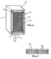
- apparatus for improving the sound quality of loudspeakers comprises a rigid shell 10 having a rear wall, two side walls 11 and 12, a top wall 13 and a base 14 all internally lined with sound absorbing material 15.
- the front of the shell is open but this could be covered with a removable panel of material which permits sound to pass therethrough in an undistorted manner.
- the shell 10 is adapted to fit over an existing loudspeaker enclosure, typically in the form of a cabinet 16, (housing one or more loudspeakers) preferably with a clearance of typically 2 to 3 mm. between the inner surface of the sound absorbing material 15 and the outer surface of the cabinet 16.
- the shell 10 may be mounted on a speaker stand 17 or on the floor.
- a soft foam sealing strip may be used on the inner edge of the shell to form a seal.
- the shell 10 is ideally isolated from the loudspeaker cabinet 16.
- the loudspeaker cabinet 16 will generally be supported on a plurality of support members, such as pins or spikes, upstanding from the base 14 of the shell 10.
- the speaker cabinet could be mounted directly on the base 14 of the shell 10.
- the shell may be coupled to the floor either directly or via a sub-frame/floor spikes as necessary.
- the shell 10 has no base.
- the shell 10 is typically made from panels of wood, M.D.F. or chipboard.
- the sound absorbing material typically comprises a single layer of sound absorbing material, preferably a foam material such as melamine foam, polyurethane foam or polyether foam.
- the sound absorbing material may comprise at least two, and as shown in Figure 2 three, layers 20 of compressible sound absorbing material, and a barrier layer 21 between the or each pair of adjacent compressible layers 20.
- the compressible sound absorbing material 20 is preferably a foam material.
- the innermost foam layer absorbs high frequency sound energy.
- the inner barrier layer minimises the low frequency sound.
- the middle foam layer absorbs vibration of the inner barrier layer.
- the outer foam layer damps any vibration which may occur in the panel to which it is fixed.
- the barrier layer(s) 21 are denser than the compressible sound absorbing material 20 and are typically formed of "dead rubber” sheet or bituminous or lead damping material.
- the particular make up of the absorbent material may be optimised to suit the speaker system.
- An angled or rounded moulding may be fixed to the front edge of the shell 10 adjacent to the drive unit baffle of the loudspeaker. This is to ensure good sound diffraction and to cover the exposed edge of the shell and sound absorbent material whilst imparting additional edge stiffness to the shell panels.
Landscapes
- Health & Medical Sciences (AREA)
- Otolaryngology (AREA)
- Physics & Mathematics (AREA)
- Engineering & Computer Science (AREA)
- Acoustics & Sound (AREA)
- Signal Processing (AREA)
- Details Of Audible-Bandwidth Transducers (AREA)
Applications Claiming Priority (2)
| Application Number | Priority Date | Filing Date | Title |
|---|---|---|---|
| GBGB9901187.6A GB9901187D0 (en) | 1999-01-21 | 1999-01-21 | Apparatus for and a method of improving the sound quality of loudspeakers |
| GB9901187 | 1999-01-21 |
Publications (2)
| Publication Number | Publication Date |
|---|---|
| EP1022928A2 true EP1022928A2 (fr) | 2000-07-26 |
| EP1022928A3 EP1022928A3 (fr) | 2002-11-27 |
Family
ID=10846158
Family Applications (1)
| Application Number | Title | Priority Date | Filing Date |
|---|---|---|---|
| EP00300282A Withdrawn EP1022928A3 (fr) | 1999-01-21 | 2000-01-17 | Dispositif et procédé pour améliorer la qualité du son dans les haut-parleur |
Country Status (2)
| Country | Link |
|---|---|
| EP (1) | EP1022928A3 (fr) |
| GB (2) | GB9901187D0 (fr) |
Families Citing this family (1)
| Publication number | Priority date | Publication date | Assignee | Title |
|---|---|---|---|---|
| CN202799035U (zh) * | 2012-08-28 | 2013-03-13 | 赵浩波 | 一种可吸附固定的内置电源音箱结构 |
Family Cites Families (5)
| Publication number | Priority date | Publication date | Assignee | Title |
|---|---|---|---|---|
| US4313521A (en) * | 1980-06-16 | 1982-02-02 | Rodden M Raymond | Speaker housing |
| EP0111408A1 (fr) * | 1982-12-02 | 1984-06-20 | Celestion International Limited | Enceintes de haut-parleur |
| HU193767B (en) * | 1985-05-31 | 1987-11-30 | Elektroakusztikai Gyar | Loudspeaker, favourably sound column or horn loudspeaker |
| DE4000132A1 (de) * | 1990-01-04 | 1991-07-11 | Prodan Hans Joachim | Lautsprechergehaeuse |
| US5194701A (en) * | 1991-09-11 | 1993-03-16 | N.P.L. Ltd. | Speaker structure |
-
1999
- 1999-01-21 GB GBGB9901187.6A patent/GB9901187D0/en not_active Ceased
-
2000
- 2000-01-17 GB GB0000834A patent/GB2346030A/en not_active Withdrawn
- 2000-01-17 EP EP00300282A patent/EP1022928A3/fr not_active Withdrawn
Also Published As
| Publication number | Publication date |
|---|---|
| EP1022928A3 (fr) | 2002-11-27 |
| GB9901187D0 (en) | 1999-03-10 |
| GB0000834D0 (en) | 2000-03-08 |
| GB2346030A (en) | 2000-07-26 |
Similar Documents
| Publication | Publication Date | Title |
|---|---|---|
| US4289929A (en) | Loudspeaker and enclosure combination | |
| US6332029B1 (en) | Acoustic device | |
| US5115884A (en) | Low distortion audio speaker cabinet | |
| PL182854B1 (pl) | Sposób propagowania energii akustycznej oraz urządzenie akustyczne do stosowania tego sposobu | |
| DE69601725T2 (de) | Lautsprecher mit paneelförmigen akustischen abstrahlelementen | |
| US5661271A (en) | Acoustic speaker enclosure having a stacked construction | |
| CN104272768B (zh) | 改良式扬声器音箱 | |
| US4869340A (en) | Very high performance loudspeaker enclosures | |
| US10151105B2 (en) | Acoustic panel | |
| EA002108B1 (ru) | Громкоговоритель, содержащий панелеобразный звукоизлучающий элемент | |
| JPWO1994003025A1 (ja) | スピーカシステム | |
| WO1996028949A1 (fr) | Haut-parleur | |
| JPS6365800A (ja) | スピ−カを備えた天井構造 | |
| EP1022928A2 (fr) | Dispositif et procédé pour améliorer la qualité du son dans les haut-parleur | |
| KR20090010917A (ko) | 다이어프램 및 사운드 출력 장치 | |
| HK1042012A1 (en) | Loudspeaker | |
| WO2013082594A9 (fr) | Haut-parleur plan | |
| EP0669783A1 (fr) | Enceinte de haut-parleur rotomoulée | |
| KR101207931B1 (ko) | 흡음 및 방진 기능이 향상된 음향반사판 | |
| US20070068729A1 (en) | Speaker with vibration-proof design | |
| US6571909B1 (en) | Loudspeaker enclosure | |
| US7315627B1 (en) | Sound-damping laminate for loudspeaker structure | |
| JP2003319481A (ja) | スピーカエンクロージャ | |
| KR102923845B1 (ko) | 흡음벽 설치용 허니컴 보드 스피커 | |
| WO2025236084A1 (fr) | Haut-parleur à panneau plat à réponse en fréquence à large portée |
Legal Events
| Date | Code | Title | Description |
|---|---|---|---|
| PUAI | Public reference made under article 153(3) epc to a published international application that has entered the european phase |
Free format text: ORIGINAL CODE: 0009012 |
|
| AK | Designated contracting states |
Kind code of ref document: A2 Designated state(s): AT BE CH CY DE DK ES FI FR GB GR IE IT LI LU MC NL PT SE |
|
| AX | Request for extension of the european patent |
Free format text: AL;LT;LV;MK;RO;SI |
|
| PUAL | Search report despatched |
Free format text: ORIGINAL CODE: 0009013 |
|
| AK | Designated contracting states |
Kind code of ref document: A3 Designated state(s): AT BE CH CY DE DK ES FI FR GB GR IE IT LI LU MC NL PT SE |
|
| AX | Request for extension of the european patent |
Free format text: AL;LT;LV;MK;RO;SI |
|
| AKX | Designation fees paid | ||
| REG | Reference to a national code |
Ref country code: DE Ref legal event code: 8566 |
|
| STAA | Information on the status of an ep patent application or granted ep patent |
Free format text: STATUS: THE APPLICATION IS DEEMED TO BE WITHDRAWN |
|
| 18D | Application deemed to be withdrawn |
Effective date: 20030528 |