EP1023943A2 - Dispositif à casser les bouteilles en verre - Google Patents
Dispositif à casser les bouteilles en verre Download PDFInfo
- Publication number
- EP1023943A2 EP1023943A2 EP20000101339 EP00101339A EP1023943A2 EP 1023943 A2 EP1023943 A2 EP 1023943A2 EP 20000101339 EP20000101339 EP 20000101339 EP 00101339 A EP00101339 A EP 00101339A EP 1023943 A2 EP1023943 A2 EP 1023943A2
- Authority
- EP
- European Patent Office
- Prior art keywords
- hammer
- bottle
- guide
- frame
- spring
- Prior art date
- Legal status (The legal status is an assumption and is not a legal conclusion. Google has not performed a legal analysis and makes no representation as to the accuracy of the status listed.)
- Granted
Links
- 239000011521 glass Substances 0.000 title claims description 22
- 230000000903 blocking effect Effects 0.000 claims description 12
- 210000000056 organ Anatomy 0.000 claims description 6
- 238000011084 recovery Methods 0.000 claims description 4
- 229910003460 diamond Inorganic materials 0.000 claims description 2
- 239000010432 diamond Substances 0.000 claims description 2
- 239000000463 material Substances 0.000 claims description 2
- 230000000284 resting effect Effects 0.000 abstract 1
- 101100536354 Drosophila melanogaster tant gene Proteins 0.000 description 2
- 239000012634 fragment Substances 0.000 description 2
- 235000003434 Sesamum indicum Nutrition 0.000 description 1
- 244000000231 Sesamum indicum Species 0.000 description 1
- 230000007547 defect Effects 0.000 description 1
- 239000002184 metal Substances 0.000 description 1
- 239000007769 metal material Substances 0.000 description 1
- 238000004064 recycling Methods 0.000 description 1
- 230000002787 reinforcement Effects 0.000 description 1
- 239000011435 rock Substances 0.000 description 1
- 239000002699 waste material Substances 0.000 description 1
Images






Classifications
-
- B—PERFORMING OPERATIONS; TRANSPORTING
- B02—CRUSHING, PULVERISING, OR DISINTEGRATING; PREPARATORY TREATMENT OF GRAIN FOR MILLING
- B02C—CRUSHING, PULVERISING, OR DISINTEGRATING IN GENERAL; MILLING GRAIN
- B02C19/00—Other disintegrating devices or methods
- B02C19/0056—Other disintegrating devices or methods specially adapted for specific materials not otherwise provided for
- B02C19/0081—Other disintegrating devices or methods specially adapted for specific materials not otherwise provided for specially adapted for breaking-up bottles
- B02C19/0087—Other disintegrating devices or methods specially adapted for specific materials not otherwise provided for specially adapted for breaking-up bottles for glass bottles
-
- Y—GENERAL TAGGING OF NEW TECHNOLOGICAL DEVELOPMENTS; GENERAL TAGGING OF CROSS-SECTIONAL TECHNOLOGIES SPANNING OVER SEVERAL SECTIONS OF THE IPC; TECHNICAL SUBJECTS COVERED BY FORMER USPC CROSS-REFERENCE ART COLLECTIONS [XRACs] AND DIGESTS
- Y02—TECHNOLOGIES OR APPLICATIONS FOR MITIGATION OR ADAPTATION AGAINST CLIMATE CHANGE
- Y02W—CLIMATE CHANGE MITIGATION TECHNOLOGIES RELATED TO WASTEWATER TREATMENT OR WASTE MANAGEMENT
- Y02W30/00—Technologies for solid waste management
- Y02W30/50—Reuse, recycling or recovery technologies
- Y02W30/60—Glass recycling
Definitions
- the present invention relates to a device for breaking bottles into glass intended to equip skips or waste reception containers of glass in order to reduce the storage volume and save space in said skips or said containers.
- An object of the invention is to provide a device for breaking bottles into glass intended to equip skips or containers for receiving debris glass which overcomes the defects found on the devices of the prior art.
- the device cited above which is characterized in that it includes a frame for fixing the device to the container, guide means mounted on the frame for receiving and bottle guide, a hammer rotatably mounted on the frame pushed in guide of the guide by a spring, a hammer blocking member in a arming position of the spring, said member comprising a stop on which a bottle to break can support to rotate the organ to against return means and thus release the hammer in order to break the bottle, and a hammer reset mechanism to allow the organ to automatically return to the hammer blocking position thanks to its means of recall.
- An advantage of this device is to save space in the skips or glass recovery containers. This device makes it possible to triple the amount of glass recovered, resulting in savings in transport to recycling location (1 transport instead of 3) as well as the reduction of pollution related to it.
- Another advantage of the device is that the bottle is supported by guide means serving as support to allow effectively break the bottle guided by the hammer.
- the device consists of a metal frame which is fixed around the container hole allowing the bottle to be destroyed to pass through.
- the guiding means keep the bottle in its path up to a stopper, of special shape, which receives the bottom of the bottle. Speak weight of the bottle or by pushing said bottle against the stopper, this triggers the brake, freeing the hammer which breaks the bottle. The glass fragments fall to the bottom of the container.
- a lever articulated on the chassis that is to say the frame of the device, resets the hammer so that it is in the position of operation. It is held in this position by the brake which has resumed its position thanks to its recall means. The lever returns automatically in its initial position against a stop on the chassis thanks to a spring reminder.
- the device for breaking bottles into glass consists of a frame 1 fixed by screws 7 around the existing hole on the container.
- the frame is usually made of metallic material, but other equally resistant materials could also be used.
- a rubber seal 10 between the frame 1 and the container lid, gives a perfect support for good fixation.
- This guide 2 On the frame 1 are fixed guide means 2 for receiving a bottle to break and guide it.
- This guide 2 which for example has a section transverse V-shaped along its length, allows the bottle to slide down.
- a leaf spring 23 fixed on an opposite part of the frame 1 press the bottle against guide 2 along its path.
- a hammer 5 is rotatably mounted around an axis 12 'fixed on a part of the frame 1.
- the hammer 5 is pushed by a powerful spring 12 in the form of spiral placed around the axis of rotation 12 'in the direction of the guide 2.
- the force of this spring must be such as to allow the hammer to break the bottle placed on the guide.
- Two arms 16 are fixed to the frame at the axis of rotation 12 'of the hammer which pivots between the two arms 16.
- the head hammer is specially studied for its shape and its weight. On the figures, this head is only represented in a rectangular shape, but it might be conceivable that it includes a point, for example in diamond, on the side coming into contact with the bottle.
- a rotary locking member 4 of the hammer At the other end of the two arms 16 is the axis of rotation 11 a rotary locking member 4 of the hammer in the cocking position.
- a return spring in the form of a spiral not visible in FIGS. 1 and 2 is arranged around the axis 11 in order to impose on the blocking member a movement towards the opening for introducing a bottle of the device.
- a stop of this blocking member in its initial position can be formed by the hammer itself.
- the hammer reset mechanism is formed in this first embodiment by a manual lever 6 rotatably mounted on the frame 1 in a central position.
- a manual lever 6 By pulling on an outer handle of lever 6, which pivots around the point of rotation 13 against a return spring 8 intended to return the lever to a rest position against a stop 18 of the frame, an interior part 6 ′ of the lever pushes the hammer 5 so that it reset and return to its initial position blocked by the locking member 4.
- the hammer once armed rests on a central support 15 'of the blocking which has returned to its initial position thanks to its return spring placed around the axis of rotation 11.
- a pivot 14 rotatably mounted in a point 14 'on one side of the hammer head pushes an offset cam 15 of the locking member 4 which moves it away from its trajectory and thus releases the passage for glass debris that would have been trapped between a stop 3 and guide 2 when breaking a previous bottle.
- the rotary pivot 14 abuts against two pins 17 of the hammer.
- the lever 6 is repositioned at its starting point against a stop 18 of the frame by the spring 8.
- the bottom of the bottle comes to rest on the stop 3 of the locking member 4 of the hammer 5 constituting a hammer brake.
- the brake 4 By pressing the bottom of the bottle against the stop 3, the brake 4 by pivoting relative to the point of rotation 11 thus releases the hammer 5 which breaks the bottle supported by the guide 2.
- the shape of the stop 3 is studied so that the bottle is well supported against the guide 2 also helped by the leaf spring 23.
- An elastic seal 22 is located on the door to close opening the container.
- This door in this first embodiment exclusively used to push the bottle towards the stop of the organ blocking to prevent the neck from being expelled out of the container during the breakage of the bottle.
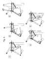
- FIG. 3 represents a kinematics of the different stages which allow to break the bottles with the device of the first form of execution.
- the hammer In the first position, the hammer is disarmed. In the second position, the lever is actuated to be able to arm the hammer and keep it in this armed position thanks to the blocking member. In the third position, the lever is released and automatically returns to its rest thanks to its return spring, while a bottle is introduced through the opening of the container and slides along the guide. In the fourth position, the bottle arrives against a stop of the rocker making it rotate around its axis of rotation to release the hammer. In the fifth position, the hammer thus released strikes the bottle in order to break it.
- FIGS. 4a, 4b and 5 a second embodiment of the device to break the bottles is shown.
- This device is intended to be mounted on an opening of a glass recovery container, said glass opening located on a wall of the container, said device being in an inclined position of 125 °.
- This device is used for large containers or truck bodies that have openings on the sides.
- the same elements of these figures 4a, 4b and 5 bear reference signs identical to those of FIGS. 1 and 2, and will not be explained in detail in this second embodiment since the principle of arming the hammer 5 by the lever 6 and the locking member 4 of the hammer are by principle identical to the device of the first embodiment.
- Leverage 6 rests on a stopper 18 and can be actuated until it comes in contact with a second stop 19 where the hammer is in a position army.
- the door 21 passing between two branches of the lever 6 is articulated in this second embodiment along an axis of rotation 7 'placed between two inside faces of the frame 1.
- a reinforcement on the door not visible on the figures is provided so that the bottle remains in contact with the guide during its pushed by said door towards the stop 3.
- This same stop at the end of the locking member 4 has an inverted L shape for also prevent the bottle from lifting when the bottle is pushed.
- the leaf spring 23 does not have exclusively for the purpose of strongly pressing the bottle against the guide being given that the guide is no longer in the vertical position as for the first embodiment and that the bottle is pressed against said guide by its own weight.
- This leaf spring also serves to protect the hand from user if, inadvertently, he introduces it inside the device and releases the hammer from its locked position.
- a flexible cable 20 is fixed on the one hand to the leaf spring 23 and on the other starts at a point 6 'of the lever coming into contact with the hammer 5. As soon as the lever 6 is again actuated to reset the hammer, the flexible cable 20 stretches and thus causes the leaf spring 23 in its path which allows release a possible bottleneck from a previous broken bottle blocked between the blade and guide 2. In the rest position of the lever 6, the leaf spring 23 returns in its initial position and the flexible cable 20 is relaxed so as not to unnecessarily tire the leaf spring in this position.
- the cable 20 can be removed between the leaf spring and lever because in this second embodiment the blade presses the bottle less strongly against its guide which can avoid to jam a possible broken bottle neck.
- FIG. 6 represents a kinematics of the different stages which allow to break the bottles with the device of the second form of execution.
- the cable connecting the leaf spring to the point 6 'of the lever has been removed, and that said leaf spring is moved away from the guide.
- the lever In the first position, the hammer is disarmed.
- the lever In the second position, the lever is actuated to be able to arm the hammer and keep it in this armed position thanks to the blocking member.
- the lever In the third position, the lever is released and automatically returns to its rest thanks to its return spring, while a bottle is introduced through the opening of the container and slides along the guide.
- the fourth position the bottle arrives against a stop of the rocker making it rotate around its axis of rotation to release the hammer.
- the hammer thus released strikes the bottle in order to break it.
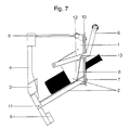
- Figure 7 shows a third embodiment of the device to break the bottles.
- This device is intended to be mounted on a opening of a glass recovery container, said opening located on a vertical wall of the container, said device being in a 125 ° tilted position.
- This device is used as for the second form of execution for large containers or dump trucks that have openings on the sides.
- the same elements of this figure 7 bear reference signs identical to those of FIGS. 1 and 2.
- the bottle to be broken is introduced through an opening of the container and is received by a guide 2 fixed to the frame 1 so that it slides down.
- This guide includes a tubular part on the top mounted on a part straight V-shaped cross section. The tubular part ensures some protection if a user puts their hand into the device and sets the hammer 5.
- the blocking device is the big difference from two other embodiments mentioned above.
- This organ is a rocker 4 having a counterweight 9 serving as means of recalling the rocks in a hammer blocking position.
- This rocker is articulated at a point 11 at the free end of the guide 2 and abuts against said guide in the locking position.
- a stop 3 of the rocker has an inclined face for receiving the bottom of the bottle to allow it to be pressed against the guide to ensure that the hammer can break it.
- the end opposite the counterweight of the scale acts as a brake on the hammer, keeping it in the armed position.
- FIG. 8 represents a kinematics of the different stages which allow to break the bottles with the device of the third form of execution.
- the lever In the first position, the hammer is disarmed.
- the lever In the second position, the lever is actuated to be able to arm the hammer and the keep in this armed position thanks to the locking lever.
- the lever In the third position, the lever is released and automatically returns to its rest position thanks to its return spring, while a bottle is introduced by the opening of the container and slides along the guide.
- the bottle arrives against a stop of the rocker making it pivot around its axis of rotation to release the hammer.
- the hammer In the fifth position, the hammer thus released strikes the bottle in order to to break.
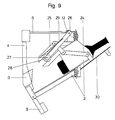
- FIG. 9 represents a fourth embodiment of the device in as a variant of the third embodiment of Figure 7.
- the reset mechanism used to reset the hammer is replaced by a door 30 whose axis of rotation is placed on an outside side of the frame at the start of guide 2.
- a part of the guide 2 of tubular shape moves by opening the door 30 for guiding the bottle.
- the functions are identical to the other embodiments, namely support from the bottom of the bottle to the stop 3 which activates the brake 4 allowing the hammer 5 to break the bottle and broken glass to fall to the bottom of the container.
- the lever arms 24, 25 and 26 are actuated thus raising the axis 27, itself driven by two pulleys 28, which slide in the lever 25.
- the hammer 5 thus rearmed is held in place by the brake 4 which has returned to its initial position thanks to the counterweight 9.
- the door 30 remains closed thanks to spring 29.
- FIG. 10 represents a kinematics of the different stages which allow to break the bottles with the device of the fourth form of execution.
- the lever In the first position, the hammer is disarmed.
- the lever In the second position, the lever is actuated to be able to arm the hammer and the keep in this armed position thanks to the locking lever.
- the lever In the third position, the lever is released and automatically returns to its rest position thanks to its return spring, while a bottle is introduced by the opening of the container and slides along the guide.
- the bottle arrives against a stop of the rocker making it pivot around its axis of rotation to release the hammer, which, thus released, just hit the bottle to break it.
- the hammer reset mechanism may include an element motorized powered by electrical or hydraulic control means or pneumatic.
Landscapes
- Engineering & Computer Science (AREA)
- Food Science & Technology (AREA)
- Disintegrating Or Milling (AREA)
- Crushing And Pulverization Processes (AREA)
Abstract
Description
- la figure 1 représente une vue de côté d'une première forme d'exécution du dispositif selon l'invention dans une première position en tant que système vertical pour des containers à roulettes de 800 litres,
- la figure 2 représente une vue de côté du dispositif selon l'invention de la figure 1 dans une deuxième position où le marteau est armé,
- la figure 3 montre une cinématique des différentes positions de travail du dispositif de la première forme d'exécution,
- les figures 4a et 4b représentent une vue de côté et une vue de dessus d'une deuxième forme d'exécution du dispositif selon l'invention dans une première position en tant que système incliné à 125° pour des gros containers ou des bennes de camions,
- la figure 5 représente une vue de côté du dispositif selon l'invention des figures 4a et 4b dans une deuxième position où le marteau est armé,
- la figure 6 montre une cinématique des différentes positions de travail du dispositif de la deuxième forme d'exécution,
- la figure 7 représente une vue de côté d'une troisième forme d'exécution du dispositif selon l'invention,
- la figure 8 montre les différentes positions de travail du dispositif de la troisième forme d'exécution,
- la figure 9 représente une vue de côté d'une quatrième forme d'exécution du dispositif selon l'invention, et
- la figure 10 montre les différentes positions de travail du dispositif de la quatrième forme d'exécution.
Claims (13)
- Dispositif pour casser des bouteilles en verre destiné à être monté sur un container de récupération du verre en coopération avec une ouverture de réception des bouteilles placée sur le dessus ou sur une paroi verticale ou sur une face inclinée dudit container, caractérisé en ce qu'il comprend un cadre (1) pour la fixation du dispositif au container, des moyens de guidage (2) monté sur le cadre pour la réception et le guidage de la bouteille, un marteau (5) monté rotatif sur le cadre poussé en direction du guide par un ressort (12), un organe de blocage (4) du marteau dans une position d'armement du ressort, ledit organe comprenant une butée (3) sur laquelle une bouteille à casser peut prendre appui pour faire pivoter l'organe à l'encontre de moyens de rappel (9) et pour ainsi libérer le marteau afin de casser la bouteille, et un mécanisme de réarmement (6, 20) du marteau pour permettre à l'organe de revenir automatiquement en position de blocage du marteau grâce à ses moyens de rappel (9).
- Dispositif selon la revendication 1, caractérisé en ce que l'organe de blocage est une bascule (4), et en ce que les moyens de rappel (9) sont constitués par un contrepoids de la bascule pour la ramener dans une position d'armement du marteau quand le mécanisme de réarmement est activé, l'articulation de la bascule se trouvant à l'extrémité libre des moyens de guidage (2).
- Dispositif selon la revendication 1, caractérisé en ce que les moyens de rappel (9) sont constitués par un ressort de rappel disposé sur l'axe de rotation (11) de l'organe de blocage (4).
- Dispositif selon la revendication 3, caractérisé en ce que le ressort de rappel (9) et l'axe de rotation (11) de l'organe de blocage sont disposés à l'extrémité libre de bras, dont l'autre extrémité est fixée sur le cadre du côté opposé aux moyens de guidage (2), l'extrémité des bras fixée audit cadre se trouvant sur l'axe de rotation (12') du marteau (5).
- Dispositif selon l'une des revendications 1 à 4, caractérisé en ce que le mécanisme de réarmement est un levier (6) monté rotatif sur le cadre du dispositif dont une extrémité sert à pousser le marteau à l'encontre de son ressort (12) jusqu'à sa position armée et l'autre extrémité peut être activée manuellement.
- Dispositif selon l'une des revendications 1 à 4, caractérisé en ce que le mécanisme de réarmement est constitué par une porte à pivotement (30) sur le cadre au niveau de l'ouverture de réception d'une bouteille et par des bras articulés (24, 25, 26) dont une partie vient pousser le marteau dans sa position d'armement lorsque la porte est fermée.
- Dispositif selon l'une des revendications 5 et 6, caractérisé en ce que le levier ou la porte sont ramenés dans une position de repos par un autre ressort de rappel (8, 29).
- Dispositif selon l'une des revendications précédentes, caractérisé en ce que la face de la butée (3) en contact avec une bouteille est inclinée de façon à permettre à la bouteille de s'appuyer contre le guide sur un côté opposé au marteau et de faciliter le pivotement de l'organe de blocage (4).
- Dispositif selon l'une des revendications précédentes, caractérisé en ce que l'extrémité du marteau venant en contact avec une bouteille a une forme de pointe, et en ce que la pointe est en un matériau plus dur que le verre, de préférence en diamant.
- Dispositif selon la revendication 1, caractérisé en ce que le ressort est monté en forme de spirale autour de l'axe de rotation du marteau et en ce que l'axe de rotation (12') du marteau est parallèle à l'axe de rotation (11) de l'organe de blocage (4).
- Dispositif selon la revendication 1, caractérisé en ce que les moyens de guidage (2) sont constitués par un guide tubulaire ou par un guide rectiligne de section transversale en forme de V, et en ce qu'une lame ressort (23) fixée au cadre sur un côté opposé au guide est destinée à pousser la bouteille à casser contre le guide.
- Dispositif selon la revendication 11, caractérisé en ce qu'un câble flexible (20) est fixé d'une part à la lame ressort (23) et d'autre part à l'extrémité du mécanisme de réarmement (6) venant en contact avec le marteau (5), dans une position de repos du mécanisme le câble étant détendu, alors qu'en position d'armement du marteau il tire la lame ressort dans une direction opposée aux moyens de guidage (2).
- Dispositif selon la revendication 1, caractérisé en ce qu'une porte (21) montée à pivotement sur une partie extérieure du cadre (1) ferme l'ouverture du container et permet de pousser la bouteille introduite par l'ouverture en direction de la butée (3) de l'organe de blocage (4).
Applications Claiming Priority (4)
| Application Number | Priority Date | Filing Date | Title |
|---|---|---|---|
| CH14499 | 1999-01-27 | ||
| CH14499 | 1999-01-27 | ||
| CH164999 | 1999-09-09 | ||
| CH164999 | 1999-09-09 |
Publications (3)
| Publication Number | Publication Date |
|---|---|
| EP1023943A2 true EP1023943A2 (fr) | 2000-08-02 |
| EP1023943A3 EP1023943A3 (fr) | 2001-01-10 |
| EP1023943B1 EP1023943B1 (fr) | 2003-04-16 |
Family
ID=25683655
Family Applications (1)
| Application Number | Title | Priority Date | Filing Date |
|---|---|---|---|
| EP20000101339 Expired - Lifetime EP1023943B1 (fr) | 1999-01-27 | 2000-01-24 | Dispositif à casser les bouteilles en verre |
Country Status (4)
| Country | Link |
|---|---|
| EP (1) | EP1023943B1 (fr) |
| AT (1) | ATE237403T1 (fr) |
| DE (1) | DE60002110D1 (fr) |
| ES (1) | ES2197027T3 (fr) |
Cited By (1)
| Publication number | Priority date | Publication date | Assignee | Title |
|---|---|---|---|---|
| US10947147B2 (en) | 2016-08-19 | 2021-03-16 | Gabriel Trujillo Gonzalez | Device and method for fracturing a container and container comprising such a device |
Citations (1)
| Publication number | Priority date | Publication date | Assignee | Title |
|---|---|---|---|---|
| CH680051A5 (en) | 1990-09-04 | 1992-06-15 | Rudolf Dobler | Bottle destruction mechanism inside collecting hopper - has external handle lifting drop weight above bottle on sloping track |
Family Cites Families (7)
| Publication number | Priority date | Publication date | Assignee | Title |
|---|---|---|---|---|
| US2142915A (en) * | 1936-03-19 | 1939-01-03 | Ospalewicz Peter | Bottle crusher |
| US2177926A (en) * | 1936-05-11 | 1939-10-31 | Heman | Safety bottle breaker |
| US2235712A (en) * | 1938-01-15 | 1941-03-18 | Norman Lehr | Bottle crushing apparatus |
| US2466151A (en) * | 1946-12-19 | 1949-04-05 | Carmel William | Bottle crushing device |
| US2655320A (en) * | 1951-08-06 | 1953-10-13 | John M Westrate | Bottle-breaker |
| CH500011A (de) * | 1968-02-24 | 1970-12-15 | M & E Metall U Elektrohandelsg | Vorrichtung zur Zertrümmerung zerbrechlicher Hohlkörper, wie Flaschen oder Konservengläser |
| GB1592547A (en) * | 1977-12-23 | 1981-07-08 | Rinfret J H T | Apparatus for shattering frangible articles |
-
2000
- 2000-01-24 DE DE60002110T patent/DE60002110D1/de not_active Expired - Lifetime
- 2000-01-24 ES ES00101339T patent/ES2197027T3/es not_active Expired - Lifetime
- 2000-01-24 EP EP20000101339 patent/EP1023943B1/fr not_active Expired - Lifetime
- 2000-01-24 AT AT00101339T patent/ATE237403T1/de not_active IP Right Cessation
Patent Citations (1)
| Publication number | Priority date | Publication date | Assignee | Title |
|---|---|---|---|---|
| CH680051A5 (en) | 1990-09-04 | 1992-06-15 | Rudolf Dobler | Bottle destruction mechanism inside collecting hopper - has external handle lifting drop weight above bottle on sloping track |
Cited By (1)
| Publication number | Priority date | Publication date | Assignee | Title |
|---|---|---|---|---|
| US10947147B2 (en) | 2016-08-19 | 2021-03-16 | Gabriel Trujillo Gonzalez | Device and method for fracturing a container and container comprising such a device |
Also Published As
| Publication number | Publication date |
|---|---|
| ATE237403T1 (de) | 2003-05-15 |
| EP1023943A3 (fr) | 2001-01-10 |
| EP1023943B1 (fr) | 2003-04-16 |
| ES2197027T3 (es) | 2004-01-01 |
| DE60002110D1 (de) | 2003-05-22 |
Similar Documents
| Publication | Publication Date | Title |
|---|---|---|
| EP0509932A1 (fr) | Dispositif de verrouillage d'un couvercle sur une cuve de conteneur et conteneur comprenant un tel dispositif | |
| FR2583137A1 (fr) | Dispositif de securite pour un couvercle pouvant etre ouvert et ferme automatiquement | |
| CH628389A5 (fr) | Entrebailleur de porte. | |
| WO2010094867A1 (fr) | Caisson lumineux a ouverture compas a ressort | |
| EP1023943B1 (fr) | Dispositif à casser les bouteilles en verre | |
| FR2715965A1 (fr) | Dispositif de sécurité contre la chute, en particulier pour portes basculantes. | |
| EP1404605B1 (fr) | Dispositif de verrouillage d'une porte paliere a deverrouillage de secours independant | |
| FR2708208A1 (fr) | Dispositif d'actionnement d'un mécanisme d'amorçage d'une cartouche dégageant de l'oxygène dans un appareil de protection respiratoire. | |
| FR2759680A1 (fr) | Conteneur de stockage d'objets | |
| EP2371628B1 (fr) | Dispositif de sectionnement d'un câble disposé sur le passage d'un véhicule | |
| FR2674814A1 (fr) | Dispositif de decrochage d'ancre. | |
| FR2467800A1 (fr) | Dispositif pour limiter la hauteur de remplissage d'un receptacle a charger | |
| WO2008065309A1 (fr) | Dispositif pour l'ouverture d'un bivalve | |
| FR2602585A1 (fr) | Dispositif de retenue ou de largage d'un fil d'armement de fusees de projectiles | |
| FR2952280A1 (fr) | Parasol de securite pour le vent a declenchement par le bas | |
| FR2606821A1 (fr) | Dispositif de verrouillage en position d'accrochage d'un crochet de fermeture de porte | |
| BE1000392A4 (fr) | Dispositif d'accouplement et de fixation d'un verin. | |
| FR2609016A1 (fr) | Machine automatique verticale pour la coupe du verre | |
| FR2524357A1 (fr) | Ensemble de sectionnement a charge explosive | |
| FR2865998A1 (fr) | Echelle de communication entre un niveau superieur et un niveau inferieur d 'un aeronef, et aeronef muni d'une telle echelle | |
| FR3139474A1 (fr) | Dispositif de commande à percussion pour extincteur à pression auxiliaire et extincteur associé | |
| EP0630742A1 (fr) | Dispositif de compactage de récipients en matière plastique, notamment de bouteilles | |
| FR2919013A1 (fr) | Boite a ressort de dispositif antichute de rideau roulant a deplacement vertical munie d'une surete,et elements de surete correspondants. | |
| FR2846108A1 (fr) | Ensemble de verin et exutoire de fumee correspondant | |
| FR2743918A1 (fr) | Dispositif de securite a bris de vitre perfectionne |
Legal Events
| Date | Code | Title | Description |
|---|---|---|---|
| PUAI | Public reference made under article 153(3) epc to a published international application that has entered the european phase |
Free format text: ORIGINAL CODE: 0009012 |
|
| AK | Designated contracting states |
Kind code of ref document: A2 Designated state(s): AT BE CH CY DE DK ES FI FR GB GR IE IT LI LU MC NL PT SE |
|
| AX | Request for extension of the european patent |
Free format text: AL;LT;LV;MK;RO;SI |
|
| PUAL | Search report despatched |
Free format text: ORIGINAL CODE: 0009013 |
|
| AK | Designated contracting states |
Kind code of ref document: A3 Designated state(s): AT BE CH CY DE DK ES FI FR GB GR IE IT LI LU MC NL PT SE |
|
| AX | Request for extension of the european patent |
Free format text: AL;LT;LV;MK;RO;SI |
|
| 17P | Request for examination filed |
Effective date: 20010710 |
|
| AKX | Designation fees paid |
Free format text: AT BE CH CY DE DK ES FI FR GB GR IE IT LI LU MC NL PT SE |
|
| 17Q | First examination report despatched |
Effective date: 20020111 |
|
| GRAH | Despatch of communication of intention to grant a patent |
Free format text: ORIGINAL CODE: EPIDOS IGRA |
|
| GRAH | Despatch of communication of intention to grant a patent |
Free format text: ORIGINAL CODE: EPIDOS IGRA |
|
| GRAA | (expected) grant |
Free format text: ORIGINAL CODE: 0009210 |
|
| AK | Designated contracting states |
Designated state(s): AT BE CH CY DE DK ES FI FR GB GR IE IT LI LU MC NL PT SE |
|
| PG25 | Lapsed in a contracting state [announced via postgrant information from national office to epo] |
Ref country code: AT Free format text: LAPSE BECAUSE OF FAILURE TO SUBMIT A TRANSLATION OF THE DESCRIPTION OR TO PAY THE FEE WITHIN THE PRESCRIBED TIME-LIMIT Effective date: 20030416 Ref country code: GB Free format text: LAPSE BECAUSE OF FAILURE TO SUBMIT A TRANSLATION OF THE DESCRIPTION OR TO PAY THE FEE WITHIN THE PRESCRIBED TIME-LIMIT Effective date: 20030416 Ref country code: NL Free format text: LAPSE BECAUSE OF FAILURE TO SUBMIT A TRANSLATION OF THE DESCRIPTION OR TO PAY THE FEE WITHIN THE PRESCRIBED TIME-LIMIT Effective date: 20030416 Ref country code: CY Free format text: LAPSE BECAUSE OF FAILURE TO SUBMIT A TRANSLATION OF THE DESCRIPTION OR TO PAY THE FEE WITHIN THE PRESCRIBED TIME-LIMIT Effective date: 20030416 Ref country code: IE Free format text: LAPSE BECAUSE OF NON-PAYMENT OF DUE FEES Effective date: 20030416 Ref country code: FI Free format text: LAPSE BECAUSE OF FAILURE TO SUBMIT A TRANSLATION OF THE DESCRIPTION OR TO PAY THE FEE WITHIN THE PRESCRIBED TIME-LIMIT Effective date: 20030416 |
|
| REG | Reference to a national code |
Ref country code: GB Ref legal event code: FG4D Free format text: NOT ENGLISH |
|
| REG | Reference to a national code |
Ref country code: CH Ref legal event code: EP |
|
| REF | Corresponds to: |
Ref document number: 60002110 Country of ref document: DE Date of ref document: 20030522 Kind code of ref document: P |
|
| REG | Reference to a national code |
Ref country code: IE Ref legal event code: FG4D Free format text: FRENCH |
|
| PG25 | Lapsed in a contracting state [announced via postgrant information from national office to epo] |
Ref country code: GR Free format text: LAPSE BECAUSE OF FAILURE TO SUBMIT A TRANSLATION OF THE DESCRIPTION OR TO PAY THE FEE WITHIN THE PRESCRIBED TIME-LIMIT Effective date: 20030716 Ref country code: PT Free format text: LAPSE BECAUSE OF FAILURE TO SUBMIT A TRANSLATION OF THE DESCRIPTION OR TO PAY THE FEE WITHIN THE PRESCRIBED TIME-LIMIT Effective date: 20030716 Ref country code: SE Free format text: LAPSE BECAUSE OF FAILURE TO SUBMIT A TRANSLATION OF THE DESCRIPTION OR TO PAY THE FEE WITHIN THE PRESCRIBED TIME-LIMIT Effective date: 20030716 Ref country code: DK Free format text: LAPSE BECAUSE OF FAILURE TO SUBMIT A TRANSLATION OF THE DESCRIPTION OR TO PAY THE FEE WITHIN THE PRESCRIBED TIME-LIMIT Effective date: 20030716 |
|
| PG25 | Lapsed in a contracting state [announced via postgrant information from national office to epo] |
Ref country code: DE Free format text: LAPSE BECAUSE OF FAILURE TO SUBMIT A TRANSLATION OF THE DESCRIPTION OR TO PAY THE FEE WITHIN THE PRESCRIBED TIME-LIMIT Effective date: 20030717 |
|
| REG | Reference to a national code |
Ref country code: CH Ref legal event code: NV Representative=s name: ICB INGENIEURS CONSEILS EN BREVETS SA |
|
| NLV1 | Nl: lapsed or annulled due to failure to fulfill the requirements of art. 29p and 29m of the patents act | ||
| GBV | Gb: ep patent (uk) treated as always having been void in accordance with gb section 77(7)/1977 [no translation filed] |
Effective date: 20030416 |
|
| REG | Reference to a national code |
Ref country code: IE Ref legal event code: FD4D Ref document number: 1023943E Country of ref document: IE |
|
| REG | Reference to a national code |
Ref country code: ES Ref legal event code: FG2A Ref document number: 2197027 Country of ref document: ES Kind code of ref document: T3 |
|
| PG25 | Lapsed in a contracting state [announced via postgrant information from national office to epo] |
Ref country code: LU Free format text: LAPSE BECAUSE OF NON-PAYMENT OF DUE FEES Effective date: 20040124 |
|
| PLBE | No opposition filed within time limit |
Free format text: ORIGINAL CODE: 0009261 |
|
| STAA | Information on the status of an ep patent application or granted ep patent |
Free format text: STATUS: NO OPPOSITION FILED WITHIN TIME LIMIT |
|
| 26N | No opposition filed |
Effective date: 20040119 |
|
| PGFP | Annual fee paid to national office [announced via postgrant information from national office to epo] |
Ref country code: MC Payment date: 20081223 Year of fee payment: 10 |
|
| PGFP | Annual fee paid to national office [announced via postgrant information from national office to epo] |
Ref country code: BE Payment date: 20081230 Year of fee payment: 10 |
|
| PGFP | Annual fee paid to national office [announced via postgrant information from national office to epo] |
Ref country code: ES Payment date: 20090113 Year of fee payment: 10 |
|
| PGFP | Annual fee paid to national office [announced via postgrant information from national office to epo] |
Ref country code: IT Payment date: 20090117 Year of fee payment: 10 |
|
| PGFP | Annual fee paid to national office [announced via postgrant information from national office to epo] |
Ref country code: FR Payment date: 20090128 Year of fee payment: 10 |
|
| BERE | Be: lapsed |
Owner name: *BASSET WILLY Effective date: 20100131 |
|
| PG25 | Lapsed in a contracting state [announced via postgrant information from national office to epo] |
Ref country code: MC Free format text: LAPSE BECAUSE OF NON-PAYMENT OF DUE FEES Effective date: 20100131 |
|
| REG | Reference to a national code |
Ref country code: FR Ref legal event code: ST Effective date: 20100930 |
|
| PG25 | Lapsed in a contracting state [announced via postgrant information from national office to epo] |
Ref country code: FR Free format text: LAPSE BECAUSE OF NON-PAYMENT OF DUE FEES Effective date: 20100201 |
|
| PG25 | Lapsed in a contracting state [announced via postgrant information from national office to epo] |
Ref country code: BE Free format text: LAPSE BECAUSE OF NON-PAYMENT OF DUE FEES Effective date: 20100131 |
|
| PGFP | Annual fee paid to national office [announced via postgrant information from national office to epo] |
Ref country code: CH Payment date: 20101223 Year of fee payment: 12 |
|
| REG | Reference to a national code |
Ref country code: ES Ref legal event code: FD2A Effective date: 20110330 |
|
| PG25 | Lapsed in a contracting state [announced via postgrant information from national office to epo] |
Ref country code: IT Free format text: LAPSE BECAUSE OF NON-PAYMENT OF DUE FEES Effective date: 20100124 |
|
| PG25 | Lapsed in a contracting state [announced via postgrant information from national office to epo] |
Ref country code: ES Free format text: LAPSE BECAUSE OF NON-PAYMENT OF DUE FEES Effective date: 20110317 |
|
| PG25 | Lapsed in a contracting state [announced via postgrant information from national office to epo] |
Ref country code: ES Free format text: LAPSE BECAUSE OF NON-PAYMENT OF DUE FEES Effective date: 20100125 |
|
| REG | Reference to a national code |
Ref country code: CH Ref legal event code: PL |
|
| PG25 | Lapsed in a contracting state [announced via postgrant information from national office to epo] |
Ref country code: LI Free format text: LAPSE BECAUSE OF NON-PAYMENT OF DUE FEES Effective date: 20120131 Ref country code: CH Free format text: LAPSE BECAUSE OF NON-PAYMENT OF DUE FEES Effective date: 20120131 |