EP1024061A2 - Connection entre un logement de gonfleur et un couvercle dans un module de coussin gonflable - Google Patents
Connection entre un logement de gonfleur et un couvercle dans un module de coussin gonflable Download PDFInfo
- Publication number
- EP1024061A2 EP1024061A2 EP00101246A EP00101246A EP1024061A2 EP 1024061 A2 EP1024061 A2 EP 1024061A2 EP 00101246 A EP00101246 A EP 00101246A EP 00101246 A EP00101246 A EP 00101246A EP 1024061 A2 EP1024061 A2 EP 1024061A2
- Authority
- EP
- European Patent Office
- Prior art keywords
- side wall
- cover cap
- airbag module
- areas
- module according
- Prior art date
- Legal status (The legal status is an assumption and is not a legal conclusion. Google has not performed a legal analysis and makes no representation as to the accuracy of the status listed.)
- Granted
Links
- 239000002184 metal Substances 0.000 claims abstract description 5
- 229920003023 plastic Polymers 0.000 claims abstract description 4
- 239000004033 plastic Substances 0.000 claims abstract description 4
- 238000005452 bending Methods 0.000 claims description 9
- 230000000284 resting effect Effects 0.000 abstract description 2
- 238000009434 installation Methods 0.000 description 2
- 208000027418 Wounds and injury Diseases 0.000 description 1
- 230000004913 activation Effects 0.000 description 1
- 230000006978 adaptation Effects 0.000 description 1
- 230000006378 damage Effects 0.000 description 1
- 239000002360 explosive Substances 0.000 description 1
- 208000014674 injury Diseases 0.000 description 1
- 238000000034 method Methods 0.000 description 1
- 229920000642 polymer Polymers 0.000 description 1
Images



Classifications
-
- B—PERFORMING OPERATIONS; TRANSPORTING
- B60—VEHICLES IN GENERAL
- B60R—VEHICLES, VEHICLE FITTINGS, OR VEHICLE PARTS, NOT OTHERWISE PROVIDED FOR
- B60R21/00—Arrangements or fittings on vehicles for protecting or preventing injuries to occupants or pedestrians in case of accidents or other traffic risks
- B60R21/02—Occupant safety arrangements or fittings, e.g. crash pads
- B60R21/16—Inflatable occupant restraints or confinements designed to inflate upon impact or impending impact, e.g. air bags
- B60R21/20—Arrangements for storing inflatable members in their non-use or deflated condition; Arrangement or mounting of air bag modules or components
- B60R21/217—Inflation fluid source retainers, e.g. reaction canisters; Connection of bags, covers, diffusers or inflation fluid sources therewith or together
Definitions
- the invention relates to an airbag module for arrangement in motor vehicle steering wheels with a pot-shaped generator carrier and a lid-shaped one Cover cap, the generator carrier and cover cap being connected to one another at the edge are and form a receiving space for the airbag.
- cover cap of an airbag module is usually a Actuator for the vehicle horn is designed and against a Restoring force approximately parallel to the steering wheel axis by at least the contact distance is arranged movable relative to the steering wheel.
- connection between the cover cap and generator carrier in With regard to an inexpensive installation, it is designed as simply as possible and preferably can be produced without any tools.
- cover cap and generator carrier do not always optimally meet the aforementioned requirements, so that one is constantly striving to further improve these connections.
- motor vehicle steering wheels are also constantly being developed, what about this can lead to the fact that conventional fastening methods are no longer applicable and therefore also have to be modified.
- the invention is based, for an airbag module the task mentioned type to design the components generator carrier and cover cap and to coordinate that improved, simple, all functional Required connection between these two parts achieved can be, in particular, the demand for a short Assembly time can be optimally fulfilled.
- the proposed solution assumes that a sufficient mutual positioning and fixing of generator carrier and cover cap can be achieved in a plane perpendicular to the steering wheel axis if on Generator carrier and corresponding to each other on the cover cap concentrically adjacent wall areas are provided, the interacting already a reliable, two-dimensional fastening result and only by an exact definition of both parts relative require each other in the direction of the steering wheel axis.
- the wall of the cover cap parallel to the steering wheel axis is through Longitudinal sections divided into areas that are elastic so far outwards are spreadable so that they can be easily bent over the outside Extensions of the generator carrier can be pushed. After this These extensions snap into the recesses in the cover cap connection thus created secured by bending the bending tabs upwards.
- the radially inward projections ensure that are integrally formed on the side wall of the cap and in assembled state on the lower edge of the window cutouts in the Support the side wall of the generator support so that the connection in There is no play in the direction of the steering wheel axis, so that neither the set Contact distance still affect the horn function.
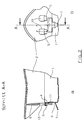
- the generator carrier (1) consists of a cup-shaped formed sheet metal section, the side wall (4) substantially parallel to Steering wheel axis (3) (see Fig. 4) is aligned.
- On the scope of the Side wall (4) are several, or at least two, fastening areas provided, each one at the top of the side wall (4) to the outside angled extension (5), one in the side wall (4) below arranged, rectangular window section (6) and one through the side Free cutting generated below the window opening (6) with the Side wall (4) connected bending tab (7).
- the Fastening areas are common stamping and stamping known from sheet metal processing Bending devices used.
- the cover cap (2) shown in Figs. 2a and 2b consists of plastic and has a circumferential, on the outside on the side wall (4) of the generator support (1) adjacent side wall (8) with vertical slots (9).
- Corresponding to the angled extensions (5) on the generator support (1) are in the Side wall (8) of the cover cap (2) radially continuous recesses (10) provided, in which the extensions 5 can engage during assembly.
- the side wall (8) of the cover cap (2) has for everyone Fastening area a radially inward, one-piece molded projection (11), which is in the assembled state on the lower Edge of the window section (6) of the side wall (4) supports. In this way is already the necessary mutual fixation of the cover cap (2) and Generator carrier (1) created.
- Fig. 4 shows a section through a cover cap according to the invention, wherein with 2 the cap and with 3 the steering wheel axis are designated.
- the radial continuous recesses 10 and the radially inward, Protrusions 11 formed in one piece are in the circumferential direction of the side wall 8 distributed so that a reliable connection between cover cap 2 and generator carrier 1 can be reached.
- the side wall 8 is through vertical, i.e. slots 9 guided approximately parallel to the steering wheel axis into individual ones Areas divided in order to spread the necessary parts during assembly facilitate. Areas of different lengths are also shown Sidewall 8. The shorter areas only extend to the lower edge of the Projections 11, while the other areas are significantly longer.
Landscapes
- Engineering & Computer Science (AREA)
- Mechanical Engineering (AREA)
- Air Bags (AREA)
- Holders For Apparel And Elements Relating To Apparel (AREA)
- Stringed Musical Instruments (AREA)
Applications Claiming Priority (2)
| Application Number | Priority Date | Filing Date | Title |
|---|---|---|---|
| DE29901286U | 1999-01-26 | ||
| DE29901286U DE29901286U1 (de) | 1999-01-26 | 1999-01-26 | Biegehaken |
Publications (3)
| Publication Number | Publication Date |
|---|---|
| EP1024061A2 true EP1024061A2 (fr) | 2000-08-02 |
| EP1024061A3 EP1024061A3 (fr) | 2001-02-14 |
| EP1024061B1 EP1024061B1 (fr) | 2003-06-04 |
Family
ID=8068471
Family Applications (1)
| Application Number | Title | Priority Date | Filing Date |
|---|---|---|---|
| EP00101246A Expired - Lifetime EP1024061B1 (fr) | 1999-01-26 | 2000-01-25 | Connection entre un support de gonfleur et un couvercle dans un module de coussin gonflable |
Country Status (5)
| Country | Link |
|---|---|
| US (1) | US6199899B1 (fr) |
| EP (1) | EP1024061B1 (fr) |
| JP (1) | JP2000211460A (fr) |
| DE (2) | DE29901286U1 (fr) |
| ES (1) | ES2199711T3 (fr) |
Cited By (1)
| Publication number | Priority date | Publication date | Assignee | Title |
|---|---|---|---|---|
| WO2003031230A3 (fr) * | 2001-10-05 | 2004-04-22 | Autoliv Asp Inc | Ergot de maintien de hauteur z d'un module de coussin de securite gonflable |
Families Citing this family (10)
| Publication number | Priority date | Publication date | Assignee | Title |
|---|---|---|---|---|
| JP2001341605A (ja) * | 2000-05-31 | 2001-12-11 | Takata Corp | エアバッグ装置 |
| DE20106695U1 (de) * | 2001-04-18 | 2001-08-23 | TRW Automotive Safety Systems GmbH & Co. KG, 63743 Aschaffenburg | Gassack-Modul |
| DE20113806U1 (de) * | 2001-08-21 | 2002-02-28 | Breed Automotive Technology, Inc., Lakeland, Fla. | Airbagmodul mit Rastverbindung |
| KR100491044B1 (ko) * | 2002-06-12 | 2005-05-24 | 현대모비스 주식회사 | 도어 부착용 외부부착구가 없는 자동차용 조수석 에어백 |
| US6942244B2 (en) * | 2003-06-25 | 2005-09-13 | Key Safety Systems, Inc. | Cover and housing structure for an airbag module |
| US7255365B2 (en) * | 2003-10-17 | 2007-08-14 | Toyoda Gosei Co., Ltd. | Air bag module with adjustable cover |
| US7393003B2 (en) * | 2005-03-31 | 2008-07-01 | Tk Holdings Inc. | Base plate attachment |
| DE102009056211B4 (de) * | 2009-11-28 | 2012-05-31 | Autoliv Development Ab | Gassackmodul |
| DE102013100664A1 (de) * | 2013-01-23 | 2014-07-24 | Fujitsu Technology Solutions Intellectual Property Gmbh | Trägerteil zum schraubenlosen Montieren eines Bauelements sowie eine Anordnung |
| KR102335527B1 (ko) * | 2017-06-27 | 2021-12-03 | 현대자동차주식회사 | 자동차용 혼 작동 장치 |
Family Cites Families (13)
| Publication number | Priority date | Publication date | Assignee | Title |
|---|---|---|---|---|
| CA2117831C (fr) * | 1993-10-13 | 1998-06-09 | Akihiro Ikeya | Dispositif de securite automatique pour occupant de vehicules munis d'un dispositif airbag |
| US5425548A (en) * | 1993-10-14 | 1995-06-20 | Morton International, Inc. | Air bag module with a centrally mounted toroidal inflator using a clamshell inflator retention system |
| US5580082A (en) | 1994-07-07 | 1996-12-03 | Toyoda Gosei Co., Ltd. | Steering wheel pad attachment structure |
| JP3198861B2 (ja) * | 1995-02-22 | 2001-08-13 | 豊田合成株式会社 | エアバッグ装置 |
| US5520411A (en) * | 1995-03-23 | 1996-05-28 | Morton International, Inc. | Cover mounting for an airbag assembly |
| JPH08295196A (ja) * | 1995-04-26 | 1996-11-12 | Kansei Corp | 自動車用エアバッグ装置 |
| JP3651068B2 (ja) * | 1995-07-31 | 2005-05-25 | 豊田合成株式会社 | エアバッグ装置 |
| JPH09142242A (ja) * | 1995-11-27 | 1997-06-03 | Toyoda Gosei Co Ltd | 助手席用エアバッグ装置 |
| JP3395497B2 (ja) * | 1996-01-10 | 2003-04-14 | 豊田合成株式会社 | エアバッグ装置のエアバッグ |
| JP3003578B2 (ja) * | 1996-07-22 | 2000-01-31 | 株式会社デンソー | 車両のエアバッグ装置用ケーシング及びそのカバー部材 |
| JP3353615B2 (ja) | 1996-07-25 | 2002-12-03 | 豊田合成株式会社 | エアバッグ装置 |
| US5794967A (en) * | 1996-08-02 | 1998-08-18 | Alliedsignal Inc. | Passenger air bag module with means for retaining an air bag deployment door to a housing |
| DE29816923U1 (de) | 1998-09-16 | 1998-11-26 | Petri Ag, 63743 Aschaffenburg | Lenkrad mit Airbagmodul |
-
1999
- 1999-01-26 DE DE29901286U patent/DE29901286U1/de not_active Expired - Lifetime
-
2000
- 2000-01-25 ES ES00101246T patent/ES2199711T3/es not_active Expired - Lifetime
- 2000-01-25 DE DE50002408T patent/DE50002408D1/de not_active Expired - Fee Related
- 2000-01-25 EP EP00101246A patent/EP1024061B1/fr not_active Expired - Lifetime
- 2000-01-26 JP JP16844A patent/JP2000211460A/ja not_active Withdrawn
- 2000-01-26 US US09/491,415 patent/US6199899B1/en not_active Expired - Fee Related
Cited By (2)
| Publication number | Priority date | Publication date | Assignee | Title |
|---|---|---|---|---|
| WO2003031230A3 (fr) * | 2001-10-05 | 2004-04-22 | Autoliv Asp Inc | Ergot de maintien de hauteur z d'un module de coussin de securite gonflable |
| US6752415B2 (en) * | 2001-10-05 | 2004-06-22 | Autoliv Asp, Inc. | Airbag module Z-height control tab |
Also Published As
| Publication number | Publication date |
|---|---|
| US6199899B1 (en) | 2001-03-13 |
| JP2000211460A (ja) | 2000-08-02 |
| ES2199711T3 (es) | 2004-03-01 |
| EP1024061B1 (fr) | 2003-06-04 |
| DE50002408D1 (de) | 2003-07-10 |
| DE29901286U1 (de) | 1999-05-12 |
| EP1024061A3 (fr) | 2001-02-14 |
Similar Documents
| Publication | Publication Date | Title |
|---|---|---|
| DE69607325T2 (de) | Schnappbefestigung für sonnenblende und elektrische verbinder für sonnenblendbefestigungen | |
| DE69315852T2 (de) | Luftsackanordnung mit gehäuse und entfaltungsdeckel mit schnappverbindung | |
| EP0983914B1 (fr) | Moyen de fixation d'un générateur de gaz dans un module de coussin gonflable | |
| DE69910181T2 (de) | Airbagmodul-mechanismus und verfahren zur montage eines airbags | |
| DE69818489T2 (de) | Schnappbefestigung | |
| DE4115873A1 (de) | Luftsackeinrichtung | |
| WO2008025641A1 (fr) | Dispositif pour fixer une unité d'airbag dans un sous-ensemble d'un véhicule automobile, en particulier dans un volant de direction, par enclenchement | |
| DE60008901T2 (de) | Montiermechanismus für ein aufblabares rückhaltesystem | |
| DE10297288B4 (de) | Lasche zur Einstellung der Z-Höhe eines Airbagmoduls | |
| EP1024061B1 (fr) | Connection entre un support de gonfleur et un couvercle dans un module de coussin gonflable | |
| DE4332080A1 (de) | Air-Bag-Anordnung | |
| DE102019131911A1 (de) | Dekorationselement und abdeckkörper für airbagvorrichtung | |
| DE60304960T2 (de) | Rastverbindung eines Airbagmoduls mit einem Fahrzeuglenkrad | |
| EP1251042B1 (fr) | Module de coussin gonflable | |
| DE69908578T2 (de) | Airbaganordnung | |
| EP0769426A2 (fr) | Boîtier pour sac gonflable | |
| EP0980797B1 (fr) | Module de sac de sécurité gonflable | |
| EP1452404B1 (fr) | Airbag pour volant de véhicule | |
| DE60201545T2 (de) | Fahrerseitiges Luftsackmodul | |
| EP0983913B1 (fr) | Coussin gonflable et fixation de coussin gonflable | |
| EP0609534B1 (fr) | Dispositif pour fixer des pièces, en particulier des pièces de véhicules à moteur | |
| EP1145922B1 (fr) | Volant de véhicule avec module de coussin gonflable déplaçable | |
| EP1524151B1 (fr) | Dispositif de commande d'avertisseur sonore pour volant de direction et module comprenant un tel dispositif | |
| EP1060957B1 (fr) | Ensemble module de coussin de sécurité, et module | |
| DE4227529C1 (de) | Kraftfahrzeug mit gegenüber von oben einwirkenden Kräften der Größenordnung eines Personenaufpralls nachgiebigen Karosseriefrontteilen |
Legal Events
| Date | Code | Title | Description |
|---|---|---|---|
| PUAI | Public reference made under article 153(3) epc to a published international application that has entered the european phase |
Free format text: ORIGINAL CODE: 0009012 |
|
| AK | Designated contracting states |
Kind code of ref document: A2 Designated state(s): DE ES FR GB IT |
|
| AX | Request for extension of the european patent |
Free format text: AL;LT;LV;MK;RO;SI |
|
| RIN1 | Information on inventor provided before grant (corrected) |
Inventor name: BURGARD, JUERGEN Inventor name: BIEBER, UDO Inventor name: KREBS, JUERGEN Inventor name: BATHON, MICHAEL Inventor name: KULLMANN, KURT |
|
| PUAL | Search report despatched |
Free format text: ORIGINAL CODE: 0009013 |
|
| AK | Designated contracting states |
Kind code of ref document: A3 Designated state(s): AT BE CH CY DE DK ES FI FR GB GR IE IT LI LU MC NL PT SE |
|
| AX | Request for extension of the european patent |
Free format text: AL;LT;LV;MK;RO;SI |
|
| 17P | Request for examination filed |
Effective date: 20010806 |
|
| AKX | Designation fees paid |
Free format text: DE ES FR GB IT |
|
| GRAH | Despatch of communication of intention to grant a patent |
Free format text: ORIGINAL CODE: EPIDOS IGRA |
|
| GRAH | Despatch of communication of intention to grant a patent |
Free format text: ORIGINAL CODE: EPIDOS IGRA |
|
| GRAA | (expected) grant |
Free format text: ORIGINAL CODE: 0009210 |
|
| AK | Designated contracting states |
Designated state(s): DE ES FR GB IT |
|
| REG | Reference to a national code |
Ref country code: GB Ref legal event code: FG4D Free format text: NOT ENGLISH |
|
| REF | Corresponds to: |
Ref document number: 50002408 Country of ref document: DE Date of ref document: 20030710 Kind code of ref document: P |
|
| RAP2 | Party data changed (patent owner data changed or rights of a patent transferred) |
Owner name: TRW AUTOMOTIVE SAFETY SYSTEMS GMBH |
|
| GBT | Gb: translation of ep patent filed (gb section 77(6)(a)/1977) | ||
| REG | Reference to a national code |
Ref country code: ES Ref legal event code: FG2A Ref document number: 2199711 Country of ref document: ES Kind code of ref document: T3 |
|
| ET | Fr: translation filed | ||
| PLBE | No opposition filed within time limit |
Free format text: ORIGINAL CODE: 0009261 |
|
| STAA | Information on the status of an ep patent application or granted ep patent |
Free format text: STATUS: NO OPPOSITION FILED WITHIN TIME LIMIT |
|
| 26N | No opposition filed |
Effective date: 20040305 |
|
| PGFP | Annual fee paid to national office [announced via postgrant information from national office to epo] |
Ref country code: GB Payment date: 20041210 Year of fee payment: 6 |
|
| PGFP | Annual fee paid to national office [announced via postgrant information from national office to epo] |
Ref country code: FR Payment date: 20050105 Year of fee payment: 6 |
|
| PGFP | Annual fee paid to national office [announced via postgrant information from national office to epo] |
Ref country code: ES Payment date: 20050120 Year of fee payment: 6 |
|
| PG25 | Lapsed in a contracting state [announced via postgrant information from national office to epo] |
Ref country code: GB Free format text: LAPSE BECAUSE OF NON-PAYMENT OF DUE FEES Effective date: 20060125 |
|
| PG25 | Lapsed in a contracting state [announced via postgrant information from national office to epo] |
Ref country code: ES Free format text: LAPSE BECAUSE OF NON-PAYMENT OF DUE FEES Effective date: 20060126 |
|
| PG25 | Lapsed in a contracting state [announced via postgrant information from national office to epo] |
Ref country code: FR Free format text: LAPSE BECAUSE OF NON-PAYMENT OF DUE FEES Effective date: 20060131 |
|
| PGFP | Annual fee paid to national office [announced via postgrant information from national office to epo] |
Ref country code: IT Payment date: 20060131 Year of fee payment: 7 |
|
| GBPC | Gb: european patent ceased through non-payment of renewal fee |
Effective date: 20060125 |
|
| REG | Reference to a national code |
Ref country code: FR Ref legal event code: ST Effective date: 20060929 |
|
| REG | Reference to a national code |
Ref country code: ES Ref legal event code: FD2A Effective date: 20060126 |
|
| PGFP | Annual fee paid to national office [announced via postgrant information from national office to epo] |
Ref country code: DE Payment date: 20090130 Year of fee payment: 10 |
|
| PG25 | Lapsed in a contracting state [announced via postgrant information from national office to epo] |
Ref country code: IT Free format text: LAPSE BECAUSE OF NON-PAYMENT OF DUE FEES Effective date: 20070125 |
|
| PG25 | Lapsed in a contracting state [announced via postgrant information from national office to epo] |
Ref country code: DE Free format text: LAPSE BECAUSE OF NON-PAYMENT OF DUE FEES Effective date: 20100803 |