EP1024087A2 - Dispositif pour fabriquer et envelopper des portions fondues - Google Patents
Dispositif pour fabriquer et envelopper des portions fondues Download PDFInfo
- Publication number
- EP1024087A2 EP1024087A2 EP00101234A EP00101234A EP1024087A2 EP 1024087 A2 EP1024087 A2 EP 1024087A2 EP 00101234 A EP00101234 A EP 00101234A EP 00101234 A EP00101234 A EP 00101234A EP 1024087 A2 EP1024087 A2 EP 1024087A2
- Authority
- EP
- European Patent Office
- Prior art keywords
- melt
- film
- grid matrix
- recesses
- portions
- Prior art date
- Legal status (The legal status is an assumption and is not a legal conclusion. Google has not performed a legal analysis and makes no representation as to the accuracy of the status listed.)
- Withdrawn
Links
- 239000000155 melt Substances 0.000 claims abstract description 28
- 238000005520 cutting process Methods 0.000 claims abstract description 10
- 239000011159 matrix material Substances 0.000 claims description 44
- 239000004831 Hot glue Substances 0.000 claims description 8
- 238000001816 cooling Methods 0.000 claims description 5
- 239000011888 foil Substances 0.000 claims description 5
- 230000009969 flowable effect Effects 0.000 claims description 4
- 239000002826 coolant Substances 0.000 claims description 3
- 229910000831 Steel Inorganic materials 0.000 description 7
- 239000010959 steel Substances 0.000 description 7
- 238000007664 blowing Methods 0.000 description 3
- 229920001875 Ebonite Polymers 0.000 description 2
- 230000001070 adhesive effect Effects 0.000 description 2
- 230000000694 effects Effects 0.000 description 2
- 239000013013 elastic material Substances 0.000 description 2
- 238000002844 melting Methods 0.000 description 2
- 230000008018 melting Effects 0.000 description 2
- 239000000203 mixture Substances 0.000 description 2
- 238000003860 storage Methods 0.000 description 2
- 230000015572 biosynthetic process Effects 0.000 description 1
- 239000011248 coating agent Substances 0.000 description 1
- 238000000576 coating method Methods 0.000 description 1
- 230000001143 conditioned effect Effects 0.000 description 1
- 239000012943 hotmelt Substances 0.000 description 1
- 238000004519 manufacturing process Methods 0.000 description 1
- 238000000034 method Methods 0.000 description 1
- 238000000465 moulding Methods 0.000 description 1
- 239000000126 substance Substances 0.000 description 1
- 230000026676 system process Effects 0.000 description 1
Images

Classifications
-
- B—PERFORMING OPERATIONS; TRANSPORTING
- B65—CONVEYING; PACKING; STORING; HANDLING THIN OR FILAMENTARY MATERIAL
- B65B—MACHINES, APPARATUS OR DEVICES FOR, OR METHODS OF, PACKAGING ARTICLES OR MATERIALS; UNPACKING
- B65B9/00—Enclosing successive articles, or quantities of material, e.g. liquids or semiliquids, in flat, folded, or tubular webs of flexible sheet material; Subdividing filled flexible tubes to form packages
- B65B9/02—Enclosing successive articles, or quantities of material between opposed webs
- B65B9/04—Enclosing successive articles, or quantities of material between opposed webs one or both webs being formed with pockets for the reception of the articles, or of the quantities of material
- B65B9/042—Enclosing successive articles, or quantities of material between opposed webs one or both webs being formed with pockets for the reception of the articles, or of the quantities of material for fluent material
-
- B—PERFORMING OPERATIONS; TRANSPORTING
- B65—CONVEYING; PACKING; STORING; HANDLING THIN OR FILAMENTARY MATERIAL
- B65B—MACHINES, APPARATUS OR DEVICES FOR, OR METHODS OF, PACKAGING ARTICLES OR MATERIALS; UNPACKING
- B65B63/00—Auxiliary devices, not otherwise provided for, for operating on articles or materials to be packaged
- B65B63/08—Auxiliary devices, not otherwise provided for, for operating on articles or materials to be packaged for heating or cooling articles or materials to facilitate packaging
Definitions
- the invention relates to a device for manufacturing and Wrapping melt portions, especially portions of hot melt adhesive, with a rotating conveyor belt, as well as with a at least with an upper run of the conveyor belt Grid matrix with at least one extending in the conveying direction
- a series of cutouts for holding melt portions is provided with means for feeding Portions of melt in the flowable state in the recesses and coolants associated with the conveyor belt for cooling the melt portions in the grid matrix, a film feed device being assigned to the grid matrix which is a film carried along with the grid matrix as a base for the melt portions, and with at least one cross cutting device, each one Melt portion limiting film cuts with creation of free film edges from the film carried along.
- Such a device for producing and wrapping Hot melt adhesive portions are known from DE 196 32 787 A1.
- the known device is designed as a double belt system, a grid matrix running along on a lower conveyor belt is arranged.
- the upper belt of the double belt system is used to calibrate the recesses in the grid matrix introduced melt portions.
- the melt portions the recesses are pasted over a pouring head fed to the matrix.
- Both the grid matrix and thus the lower conveyor belt as well as the upper calibration belt a film web is assigned to each one, with the respective Upper or lower run of the two belts of the double belt system is carried and in a subsequent to the double belt system Process area through longitudinal and cross cutting devices to film cuts for the respective melt portions is changed.
- the upper and the lower foil lie around the melt portions so that they form a tight seal for the melt portions.
- the object of the invention is a device of the beginning to create the kind that is provided with simple means of packaged melt portions.
- a prerequisite for the solution according to the invention is that the Melt in the respective flowable state as far as possible Recess of the grid matrix is filled in that due to the Flow properties of the melt this the entire space of the Takes recess.
- the melt portions are cooled only so far that the melt is still soft Condition located to collapse without difficulty to enable. If a hot melt adhesive is provided cooling down to room temperature because of the hot melt adhesive is still sufficiently soft at room temperature. Of course however, the melt must have a temperature which is below the melting temperature of the film.
- each recess is the grid matrix with a halving the area of the recess Provide bar.
- the bar preferably has a lower one Height as the edge of the corresponding recess. In that area the recess in which the bar is provided the respective melt portion is cut out in a groove-like manner, so that this ridge area is a folding axis like a Film hinge can form if the appropriately formed Melt portion halves that still over the ridge area are connected together, can be folded.
- the bar is advantageously an integral part of the grid matrix. This allows the lattice matrix to form the Moldings can be produced in a single step.
- the grid matrix is preferably made of a hard elastomer mixture manufactured.
- the grid matrix is preferably as endless belt.
- the input side Means for embedding the film in the recesses the grid matrix provided. This can be done by appropriate chemical treatment or by electrostatic charge respectively.
- the means for embedding are particularly advantageous Intake device that the film from below on the Grid matrix and pulls into the recesses. This is preferred between the conveyor belt and the grid matrix, where the conveyor belt is preferably designed as a steel belt Vacuum created that the corresponding film sheet flat sucked into the recesses.
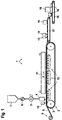
- a device 1 for producing and wrapping portions of hot melt adhesive has a single conveyor belt 2 in the form of a encircling steel band, on its surface encircling a lattice matrix made of an elastic material 3 is arranged, which together with the conveyor belt 2 runs in the direction of conveyance F.
- the grid matrix 3 and thus The steel strip 2 is also heated from above Storage container 7 stored in a flowable state Melt via a pump device 6 and a portioning device 4 in coordinated melt portions (below described in more detail) supplied.
- a film feeder 8 Before feeding the melt portions is a film web 9 by means of the grid matrix 3 a film feeder 8 applied so that the Portions of melt when pouring into corresponding recesses the grid matrix can be caught on the film web 9.
- the film web 9 is made by means of the film feed device 8 supplied without tension to the grid matrix 3, so that the film web embed in the recesses of the lattice matrix 3 can. So that the film web 9 the recesses of the grid matrix can line up flush before the portioning device 4 as a means of embedding a suction device 10 provided, their positioning in Fig. 1 only is shown schematically.
- This suction device 10 has suction nozzles located below the film web 9, preferably in the gusset of the entrance area between the Feeding the film web 9 and the drum deflection of the Steel strip 2 and the grid matrix 3 are positioned so that in the corresponding recesses of the lattice matrix, the rests tightly on the steel belt, creates a vacuum that pulls the film web into the recesses.
- melt In order to prevent the portioning device 4 supplied melt causes the film web 9 to melt, the melt is in front of the portioning device 4 by means of a Heat exchanger 5 conditioned to a temperature that is below the melting point of the film web 9.
- the device 1 points in the conveying direction F to the portioning device 4 then - various coolants 11, 12, which over a defined cooling length of the conveyor belt 2 cooling both from below and from above Effect melt portions.
- a blowing device 15 the by means of several, suitably positioned blow-out nozzles Turning through the cross and rip cutters 13, 14 created free film edges of corresponding film cuts effects on the respective melt portion.
- each melt portion 19 by means of a folding device 16 or manually relocated by being similar to one initially opened Book is folded.
- Hot melt adhesive With all sides to lay the folded film edges on top of each other. Because of the adhesive properties of the hot melt adhesive remain Hot melt portions in their folded state and are for appropriate storage or appropriate Transport wrapped securely. For later use for Formation of a melt bath melts the film without residue on.
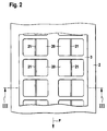
- the grid matrix 3 is made of an elastic material, in particular made from a hard rubber mixture and lies according to 2 to 4 flat on the steel strip 2.
- the Grid matrix 3 has two parallel to each other in the conveying direction F. arranged rows of recesses 20, each are square.
- the recesses 20 are as Breakthroughs designed so that when looking at the grid matrix 3 from above according to FIG. 2 in the area of the recesses 20 the surface of the steel strip 2 is visible. Every recess 20 has a running in the conveying direction F and the associated recess 20 dividing into two equal halves Bar 21 on.
- Each bar 21 is shown Embodiment integral part of the grid matrix 3 and manufactured together with this. The strips 21 can however, also introduced as separate parts in the cutouts 20 become.
- the strips 21 each design a row as a continuous ledge band.
- the crossbars of the lattice matrix 3 are the separate individual recesses 20 from one another on their underside each with a corresponding groove, through which the respective inguinal band is flush with the bottom the grid matrix 3 can be integrated.
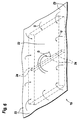
- Each bar 21 has one smaller height than the thickness of the grid matrix 3. Thereby shows the melt 22 according to FIGS. 3 and 4 in the area each bar 21 has a smaller thickness after being filled on.
- the bar 21 is the same height as the edges of the recess 20 and thus the grid matrix 3 have or are designed somewhat higher. In this Fall does not collect any melt at level 21 on. Nevertheless, a subsequent folding in the direction of the arrow D done because the film in the area of each Strip 21 acts like a film hinge. In the presentation 3 and 4 also acts in addition corresponding melt film 24 (FIGS. 5 and 6), which is in the Area of the bar 21 is located as an additional film hinge.
- Fig. 4 is the function of the blow nozzles, not shown the blowing device 15 shown that on the grid matrix First lift 3 overlying film edges 23 and by aligning the blow nozzles in the direction of the arrow U blow onto the respective melt portion 22 where they stick due to the adhesive properties of the melt portion stay.
- FIG. 1 provide two corresponding lifting plates, the same Lift both halves of the melt portion and fold them up vertically. Then the folded portion of melt filed.
Landscapes
- Engineering & Computer Science (AREA)
- Mechanical Engineering (AREA)
- Auxiliary Devices For And Details Of Packaging Control (AREA)
- Containers And Plastic Fillers For Packaging (AREA)
Applications Claiming Priority (2)
| Application Number | Priority Date | Filing Date | Title |
|---|---|---|---|
| DE29901565U | 1999-01-29 | ||
| DE29901565U DE29901565U1 (de) | 1999-01-29 | 1999-01-29 | Vorrichtung zum Herstellen und Umhüllen von Schmelzenportionen |
Publications (2)
| Publication Number | Publication Date |
|---|---|
| EP1024087A2 true EP1024087A2 (fr) | 2000-08-02 |
| EP1024087A3 EP1024087A3 (fr) | 2000-11-15 |
Family
ID=8068665
Family Applications (1)
| Application Number | Title | Priority Date | Filing Date |
|---|---|---|---|
| EP00101234A Withdrawn EP1024087A3 (fr) | 1999-01-29 | 2000-01-24 | Dispositif pour fabriquer et envelopper des portions fondues |
Country Status (2)
| Country | Link |
|---|---|
| EP (1) | EP1024087A3 (fr) |
| DE (1) | DE29901565U1 (fr) |
Cited By (5)
| Publication number | Priority date | Publication date | Assignee | Title |
|---|---|---|---|---|
| WO2004048204A1 (fr) * | 2002-11-22 | 2004-06-10 | Pörner Ingenieurgesellschaft Mbh | Procede de conditionnement de bitume |
| DE102008045025A1 (de) * | 2008-08-29 | 2010-03-25 | Multivac Sepp Haggenmüller Gmbh & Co. Kg | Einrichtung zur Herstellung von Faltpackungen |
| EP2377765A3 (fr) * | 2010-04-13 | 2011-11-02 | Heimbach GmbH & Co.KG | Confection de matière adhésive |
| DE202014102897U1 (de) | 2013-07-09 | 2014-08-12 | Heimbach Gmbh & Co. Kg | Prozessband für den Einsatz in einer Vorrichtung sowie eine Vorrichtung zur Herstellung eines Produktes unter Verwendung dieses Prozessbandes |
| CN111572907A (zh) * | 2020-04-19 | 2020-08-25 | 郭梅芳 | 一种纺织烘干机用出料折叠机构 |
Families Citing this family (2)
| Publication number | Priority date | Publication date | Assignee | Title |
|---|---|---|---|---|
| DE19941252C1 (de) * | 1999-08-31 | 2000-11-16 | Santrade Ltd | Vorrichtung zur Herstellung und Umhüllung von Schmelzenportionen |
| US6484479B1 (en) * | 2000-04-10 | 2002-11-26 | Tetra Laval Holdings & Finance, Sa | Form, fill and seal apparatus with cavity bar |
Citations (1)
| Publication number | Priority date | Publication date | Assignee | Title |
|---|---|---|---|---|
| DE19632787A1 (de) | 1996-08-15 | 1998-02-19 | Santrade Ltd | Verfahren zum Herstellen und Umhüllen von Schmelzenportionen sowie Anlage und Vorrichtung |
Family Cites Families (4)
| Publication number | Priority date | Publication date | Assignee | Title |
|---|---|---|---|---|
| SE458599B (sv) * | 1986-11-13 | 1989-04-17 | Novopolotskij Polt Inst | Foerfarande och anlaeggning foer foerpackning av svaarsmaelta bitumen i polymerfilm |
| DE3938874A1 (de) * | 1989-11-24 | 1991-05-29 | Tetra Pak Gmbh | Verfahren zur herstellung einer fliessmittelpackung, vorrichtung zur herstellung einer solchen packung und verwendung eines besonderen kunststoffes |
| DE4205919C2 (de) * | 1992-02-26 | 1994-06-23 | Fuller H B Licensing Financ | Vorrichtung zum Verpacken von fließfähig machbaren Klebstoffen |
| DE19830258A1 (de) * | 1998-07-07 | 2000-01-13 | Ritter Kg Alfred | Verfahren sowie Vorrichtung zur Herstellung verpackter schokoladenartiger Produkte und nach diesem Verfahren hergestelltes Produkt |
-
1999
- 1999-01-29 DE DE29901565U patent/DE29901565U1/de not_active Expired - Lifetime
-
2000
- 2000-01-24 EP EP00101234A patent/EP1024087A3/fr not_active Withdrawn
Patent Citations (1)
| Publication number | Priority date | Publication date | Assignee | Title |
|---|---|---|---|---|
| DE19632787A1 (de) | 1996-08-15 | 1998-02-19 | Santrade Ltd | Verfahren zum Herstellen und Umhüllen von Schmelzenportionen sowie Anlage und Vorrichtung |
Cited By (7)
| Publication number | Priority date | Publication date | Assignee | Title |
|---|---|---|---|---|
| WO2004048204A1 (fr) * | 2002-11-22 | 2004-06-10 | Pörner Ingenieurgesellschaft Mbh | Procede de conditionnement de bitume |
| RU2397930C2 (ru) * | 2002-11-22 | 2010-08-27 | Битумен Апплайд Ресёч Лимитед | Способ затаривания битумов |
| DE102008045025A1 (de) * | 2008-08-29 | 2010-03-25 | Multivac Sepp Haggenmüller Gmbh & Co. Kg | Einrichtung zur Herstellung von Faltpackungen |
| DE102008045025B4 (de) * | 2008-08-29 | 2014-05-28 | Multivac Sepp Haggenmüller Gmbh & Co. Kg | Einrichtung zur Herstellung von Faltpackungen |
| EP2377765A3 (fr) * | 2010-04-13 | 2011-11-02 | Heimbach GmbH & Co.KG | Confection de matière adhésive |
| DE202014102897U1 (de) | 2013-07-09 | 2014-08-12 | Heimbach Gmbh & Co. Kg | Prozessband für den Einsatz in einer Vorrichtung sowie eine Vorrichtung zur Herstellung eines Produktes unter Verwendung dieses Prozessbandes |
| CN111572907A (zh) * | 2020-04-19 | 2020-08-25 | 郭梅芳 | 一种纺织烘干机用出料折叠机构 |
Also Published As
| Publication number | Publication date |
|---|---|
| EP1024087A3 (fr) | 2000-11-15 |
| DE29901565U1 (de) | 1999-04-08 |
Similar Documents
| Publication | Publication Date | Title |
|---|---|---|
| DE69607941T2 (de) | Flexibler beutel mit kompressiblen, absorbierenden produkten sowie verfahren zu seiner herstellung | |
| DE68902041T2 (de) | Verfahren und geraet zum herstellen eines schlauch- bzw. beutelfoermigen behaelters sowie entsprechender behaelter. | |
| DE3106155C2 (fr) | ||
| EP2532513B1 (fr) | Sachet pour tabac ainsi que procédé et dispositif de fabrication | |
| DE2904418A1 (de) | Behaelter aus duennem flexiblem kunststoff und verfahren zu deren herstellung | |
| DE3878830T2 (de) | Kunststoffbeutel mit angeheftetem Schnurband aus Kunststoff und entsprechende Herstellungsmethoden. | |
| DE102004056043A1 (de) | Beutelpackung sowie Verfahren und Vorrichtung zum Herstellen derselben | |
| DE2249584A1 (de) | Kunststoffbeutel und verfahren zu ihrer herstellung | |
| DE60004697T2 (de) | Systeme zum warmformverfahren von materialbahnen zur herstellung von behältern | |
| EP0343266B1 (fr) | Procédé pour fabriquer des récipients à partir d'une feuille en bande et installation pour la mise en oeuvre de ce procédé | |
| CH622462A5 (fr) | ||
| CH650984A5 (de) | Verfahren zur herstellung einer verpackung, vorrichtung zur durchfuehrung des verfahrens und nach dem verfahren hergestellte verpackung. | |
| DE3602210A1 (de) | Vorrichtung zur herstellung von blocks mit mindestens einer tascheneinheit sowie tascheneinheit | |
| DE29901565U1 (de) | Vorrichtung zum Herstellen und Umhüllen von Schmelzenportionen | |
| DE60121897T2 (de) | Vorgeöffnete wiederverschliessbare Beutel | |
| DE2355208A1 (de) | Verfahren und vorrichtung zum verpacken | |
| DE3829042A1 (de) | Vakuum-verpackung, verbundfolie zur herstellung einer vakuum-verpackung, vorrichtung zur herstellung der verbundfolie sowie verfahren zur herstellung von vakuum-verpackungen | |
| EP0001386B1 (fr) | Dispositif d'emballage d'objets au moyen d'une feuille | |
| EP0490822B1 (fr) | Emballage en forme de sac tubulaire avec assistance au déchirage | |
| DE3015847A1 (de) | Verfahren und vorrichtung zum herstellen von vakuum-skin-verpackungen | |
| DE1923020A1 (de) | Behaelterkette sowie Verfahren und Vorrichtung zur Fuellung derselben | |
| DE69621261T2 (de) | Verfahren zum Herstellen von Beuteln | |
| DE10305017A1 (de) | Nadelverpackung und Nadeltasche, sowie Verpackungsverfahren | |
| DE60000572T2 (de) | Verfahren zum herstellen von wiederverschliessbaren taschen | |
| DE69919896T2 (de) | Verfahren zur herstellung einer verpackung mit peelbarer zone |
Legal Events
| Date | Code | Title | Description |
|---|---|---|---|
| PUAI | Public reference made under article 153(3) epc to a published international application that has entered the european phase |
Free format text: ORIGINAL CODE: 0009012 |
|
| AK | Designated contracting states |
Kind code of ref document: A2 Designated state(s): AT DE ES FR GB IT |
|
| AX | Request for extension of the european patent |
Free format text: AL;LT;LV;MK;RO;SI |
|
| PUAL | Search report despatched |
Free format text: ORIGINAL CODE: 0009013 |
|
| AK | Designated contracting states |
Kind code of ref document: A3 Designated state(s): AT BE CH CY DE DK ES FI FR GB GR IE IT LI LU MC NL PT SE |
|
| AX | Request for extension of the european patent |
Free format text: AL;LT;LV;MK;RO;SI |
|
| RIC1 | Information provided on ipc code assigned before grant |
Free format text: 7B 65B 63/08 A, 7B 65B 9/04 B |
|
| 17P | Request for examination filed |
Effective date: 20001227 |
|
| STAA | Information on the status of an ep patent application or granted ep patent |
Free format text: STATUS: THE APPLICATION HAS BEEN WITHDRAWN |
|
| AKX | Designation fees paid |
Free format text: AT DE ES FR GB IT |
|
| 18W | Application withdrawn |
Withdrawal date: 20010630 |