EP1024255A2 - Structure de support pour un dispositif d'épuration de gaz d'échappement - Google Patents
Structure de support pour un dispositif d'épuration de gaz d'échappement Download PDFInfo
- Publication number
- EP1024255A2 EP1024255A2 EP00100991A EP00100991A EP1024255A2 EP 1024255 A2 EP1024255 A2 EP 1024255A2 EP 00100991 A EP00100991 A EP 00100991A EP 00100991 A EP00100991 A EP 00100991A EP 1024255 A2 EP1024255 A2 EP 1024255A2
- Authority
- EP
- European Patent Office
- Prior art keywords
- support structure
- flow channels
- exhaust gas
- structure according
- flow
- Prior art date
- Legal status (The legal status is an assumption and is not a legal conclusion. Google has not performed a legal analysis and makes no representation as to the accuracy of the status listed.)
- Withdrawn
Links
Images


Classifications
-
- F—MECHANICAL ENGINEERING; LIGHTING; HEATING; WEAPONS; BLASTING
- F01—MACHINES OR ENGINES IN GENERAL; ENGINE PLANTS IN GENERAL; STEAM ENGINES
- F01N—GAS-FLOW SILENCERS OR EXHAUST APPARATUS FOR MACHINES OR ENGINES IN GENERAL; GAS-FLOW SILENCERS OR EXHAUST APPARATUS FOR INTERNAL-COMBUSTION ENGINES
- F01N3/00—Exhaust or silencing apparatus having means for purifying, rendering innocuous, or otherwise treating exhaust
- F01N3/08—Exhaust or silencing apparatus having means for purifying, rendering innocuous, or otherwise treating exhaust for rendering innocuous
- F01N3/10—Exhaust or silencing apparatus having means for purifying, rendering innocuous, or otherwise treating exhaust for rendering innocuous by thermal or catalytic conversion of noxious components of exhaust
- F01N3/24—Exhaust or silencing apparatus having means for purifying, rendering innocuous, or otherwise treating exhaust for rendering innocuous by thermal or catalytic conversion of noxious components of exhaust characterised by constructional aspects of converting apparatus
- F01N3/28—Construction of catalytic reactors
- F01N3/2803—Construction of catalytic reactors characterised by structure, by material or by manufacturing of catalyst support
- F01N3/2807—Metal other than sintered metal
- F01N3/281—Metallic honeycomb monoliths made of stacked or rolled sheets, foils or plates
- F01N3/2821—Metallic honeycomb monoliths made of stacked or rolled sheets, foils or plates the support being provided with means to enhance the mixing process inside the converter, e.g. sheets, plates or foils with protrusions or projections to create turbulence
Definitions
- the invention relates to a support structure for an exhaust gas purification device, especially for catalytic converters of internal combustion engines, with at least one metal foil, the has impressed flow channels for the exhaust gas.
- DE 27 59 559 C2 describes a matrix for a catalytic one Described reactor for exhaust gas purification in internal combustion engines been made up of at least two with catalyst material coated steel sheets. These are for education of exhaust gas flow channels between adjacent ones Steel sheets with waves that are arrow-shaped and in neighboring Steel sheets with opposite arrow direction are arranged. In this way, crosswise Flow channels formed, the turbulence of the flowing Exhaust gases should increase. It is also proposed that to wrap the matrix out of the corrugated steel sheets. In the However, there are problems in producing such a matrix, because the steel sheet through the embossed arrow structure has a high rigidity that the winding of the steel sheets difficult or even practically prevented.
- the invention has for its object to provide a support structure according to the preamble of claim 1, which has a high exhaust gas turbulence and exhaust gas mixture with a low exhaust gas back pressure and can be easily wound into a winding body.
- the waveform causes an improved exhaust gas mixing in the Flow channels within the support structure opposite one straight flow channel and yet has a lower Flow resistance like a sharp, arrow-shaped deflection of the known flow channel.
- a multilayer structure of the support structure with at least two embossed metal foils can be different Flow structures are made that are different Can produce exhaust gas mixtures.
- the maximum deflection of the wave bellies of the flow channels is taking into account the cross section of the flow channel expediently chosen such that an optical There is coverage, d. H. through the support structure or Flow channels cannot be seen through in the direction of flow become.
- the exhaust gas flow distracted in a certain direction for example if the exit angle of the flow channels of two neighboring Metal foils are on the same side of the normal, or the exhaust gas flow is swirled when the exit angle are opposite.
- the support structure with a catalytic coating it can be used to produce an exhaust gas catalytic converter be used.
- the invention Carrier structure also as a particle filter, for example as Soot filter for a diesel engine, used, in particular Flow channels in microwave form are preferred.
- Fig. 1 shows a section of a schematic representation Sheet metal or a metal foil 1 with embossed Flow channels 2, which are arranged side by side and from an entry end face 3 on the metal foil 1 which flows an exhaust gas flow into the flow channels 2 (Arrow A in Fig. 1), across the width of the metal foil 1 up to an outlet end face 4, from which the exhaust gas flow flows out (arrow B).
- the flow channels 2 are in the top view is undulated and extend along an imaginary longitudinal line 5, which in the exemplary embodiment 1 perpendicular to the entrance face 3 and the outlet end face 4 and generally the main flow direction of the exhaust gas flow along the metal foil 1 indicates, even if the entry face 3 and the Outlet end 4 not in a direction of the main flow vertical plane are arranged.
- the waveform can e.g. B. a sinusoidal waveform be approximate or match a sine wave.
- the Metal foil 1 shown in Fig. 1 contains a waveform with three bellies 6 or deflections, which is 1.5 Correspond to wave amplitudes of a sine wave.
- the flow channel 2 opens under one Exit angle ⁇ of, for example, approximately 10 to 20 ° at an angle to the longitudinal line 5, so that the outflowing exhaust gas flow (Arrow B) deflected from the straight main flow direction becomes.
- the flow channel begins at the entry end face 3 2 also at an entry angle at an angle to the longitudinal line 5, but the waveform can also be different, so that the flow channel 2 for example in to the longitudinal line 5 parallel alignment begins and ends.
- the flow channels can for example by an embossing roller in the metal foil be embossed so that by embossing on both Sides of the metal foil 1 flow channels 2 are formed.
- the metal foil 1 'shown in FIG. 2 contains flow channels 2 'with a waveform which is opposite that in FIG. 1 waveform shown has a larger wavelength.
- the flow channel 2 ' only has a wave antinode 6 'so that the waveform has 0.5 wave amplitudes of a sine wave or a comparable wave type.
- the Exit angle ⁇ ' is smaller in this embodiment as the exit angle ⁇ in the embodiment of FIG. 1.
- the size of the angle ⁇ or ⁇ ' depends on the Waveform, d. H. on the ratio of the maximum deflection of the antinodes 6 and 6 '(the amplitude of the antinodes) to the wavelength, and from the interface at which the Wave or the flow channel at the outlet end 4 is cut off or finished.
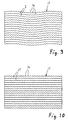
- Fig. 3 is a support structure 7 with a multi-layer Structure shown cut away.
- the one shown in Fig. 1 Metal foil 1 forms a lower layer on which a smooth one Metal foil 8, which has no embossed flow channels, is arranged.
- the smooth metal foil 8 covers her facing flow channels 2 and separates them from each other.
- the flow channels 2 there is a waveform molecular exhaust gas mixture that has an improved reaction with causes a catalytic surface of the support structure 7.
- a second metal foil 1 lies on the smooth metal foil 8 with embossed flow channels 2, which in turn from a smooth metal foil 8 is covered.
- the waveform of the two metal foils 1 and the same oblique orientation of the flow channels 2 on the outlet face 4 are correct match, so that from the support structure 7 through the Flow channels 2 of the first and second metal foils 1 flowing exhaust gas is deflected in the same direction and, if the support structure 7 to a cylindrical catalytic converter is wound, a swirl around a longitudinal axis of the catalytic converter receives. If a second catalytic converter in the Flow path is connected downstream, through the through the Swirl caused oblique flow in its catalytic Effect more active.
- the support structure 7 is shown as an example two layers each of an embossed and a smooth metal foil 1 or 8 formed, but can also consist of only one be formed such a position, which is wound to an exhaust gas catalytic converter becomes.
- the support structure 9 shown in FIG. 4 has a first, lower metal foil 1 and a second, upper metal foil 1 with Flow channels 2 with the same waveform, however the two metal foils 1 are arranged such that the respective flow channels 2 are opposite to each other, so that the exhaust gas flow from each of the two metal foils 1 in opposite directions distracted and thus swirled immediately becomes and a partial exhaust gas mixture behind the Carrier structure leads.
- FIGS. 5 and 6 of support structures 7 'and 9' correspond in their layer structure the support structures of Fig. 3 and 4, however the embossed metal foils 1 'correspond to a longer waveform of FIG. 2.
- the support structure 7 ' 5 have the flow channels 2 'on the outlet end 4 in the same direction while at the support structure 9 'of FIG. 6 point in opposite directions.
- FIG. 7 shows an exhaust gas purification device or an exhaust gas catalytic converter 10, which consists of a support structure shown in FIG. 4 9 wound and housed in a casing 11 is. There are several at the cut-open point Layers of the support structure 9 with the embossed metal foil 1 and to recognize the smooth metal foil 8. In addition to mixing there is a strong mixing within the flow channels of the exhaust gas flow after exiting the support structure or the exhaust gas catalytic converter achieved.
- FIG. 9 shows a metal foil 13 with flow channels 2 a waveform corresponding to Fig. 1.
- the Waveform a superimposed microwave the waves 14 a have a comparatively much smaller wavelength, whereby Amplitudes of the two waves are added.
- everyone wavy Flow channel 2 thus has one with additional small ones Waves 14 corrugated wall that an additional swirl in the Flow channel 2 causes.
- a metal foil 15 shown in FIG. 10 contains flow channels 2 'or 2' ', which is only a waveform with waves 14 of short wavelength and comparatively less Have amplitude or height of the wave bellies, which corresponds to the superimposed microwave according to FIG. 9.
- Flow channels 2 'and 2' 'according to FIGS. 9 and 10 supported the micro-swirling of the exhaust gas flow the adherence single particle. Because of the inertia, the contact with the flow channel walls intensified and the adhesive forces can be better exploited. Therefore, the Metal foil 15 expediently as a support structure for one Particulate filters are used.
- All metal foils and thus the support structures have one catalytic coating when used as exhaust gas catalysts for exhaust gas cleaning.
- All of the support structures shown and described can are wound to catalytic converters, the wavy embossed metal foils do not form warps. This Metal foils are also not so rigid that they wind up would hinder.
- the longitudinal line of symmetry of the waveform of the flow channels agrees with one in the examples shown Longitudinal line 5 coincides. It can also be oblique to a longitudinal line be arranged so that the main flow direction deviates from the longitudinal line due to the support structure. Thereby can additional flow diversions and exhaust gas mixtures be achieved.
- layers of the support structures can be made from any Combinations of the metal foils shown are produced, to specific mixtures of the exhaust gas flow receive.
Landscapes
- Chemical & Material Sciences (AREA)
- Chemical Kinetics & Catalysis (AREA)
- Engineering & Computer Science (AREA)
- Health & Medical Sciences (AREA)
- Toxicology (AREA)
- Combustion & Propulsion (AREA)
- Mechanical Engineering (AREA)
- General Engineering & Computer Science (AREA)
- Exhaust Gas After Treatment (AREA)
Applications Claiming Priority (2)
| Application Number | Priority Date | Filing Date | Title |
|---|---|---|---|
| DE1999103591 DE19903591A1 (de) | 1999-01-29 | 1999-01-29 | Trägerstruktur für eine Abgasreinigungsvorrichtung |
| DE19903591 | 1999-01-29 |
Publications (2)
| Publication Number | Publication Date |
|---|---|
| EP1024255A2 true EP1024255A2 (fr) | 2000-08-02 |
| EP1024255A3 EP1024255A3 (fr) | 2002-07-17 |
Family
ID=7895820
Family Applications (1)
| Application Number | Title | Priority Date | Filing Date |
|---|---|---|---|
| EP00100991A Withdrawn EP1024255A3 (fr) | 1999-01-29 | 2000-01-19 | Structure de support pour un dispositif d'épuration de gaz d'échappement |
Country Status (2)
| Country | Link |
|---|---|
| EP (1) | EP1024255A3 (fr) |
| DE (1) | DE19903591A1 (fr) |
Cited By (4)
| Publication number | Priority date | Publication date | Assignee | Title |
|---|---|---|---|---|
| WO2007064373A1 (fr) * | 2005-11-29 | 2007-06-07 | Caterpillar Inc. | Convertisseur catalytique |
| WO2008005076A1 (fr) * | 2006-06-30 | 2008-01-10 | Caterpillar Inc. | Filtre à particules |
| WO2012110395A3 (fr) * | 2011-02-18 | 2012-12-13 | Oberland Mangold Gmbh | Procédé et dispositif de séparation de particules |
| CN109922883A (zh) * | 2016-09-23 | 2019-06-21 | 巴斯夫公司 | 催化剂基质 |
Families Citing this family (2)
| Publication number | Priority date | Publication date | Assignee | Title |
|---|---|---|---|---|
| US6429261B1 (en) | 2000-05-04 | 2002-08-06 | Kimberly-Clark Worldwide, Inc. | Ion-sensitive, water-dispersible polymers, a method of making same and items using same |
| DE102014000914A1 (de) * | 2014-01-28 | 2015-07-30 | Carl Freudenberg Kg | Filterelement |
Citations (2)
| Publication number | Priority date | Publication date | Assignee | Title |
|---|---|---|---|---|
| DE2759559C2 (de) | 1977-07-26 | 1985-06-27 | Süddeutsche Kühlerfabrik Julius Fr. Behr GmbH & Co. KG, 7000 Stuttgart | Matrix für einen katalytischen Reaktor zur Abgasreinigung bei Brennkraftmaschinen |
| EP0512659A2 (fr) * | 1991-05-06 | 1992-11-11 | W.R. Grace & Co.-Conn. | Bande de feuille métallique mince ondulée |
Family Cites Families (7)
| Publication number | Priority date | Publication date | Assignee | Title |
|---|---|---|---|---|
| DE3723478A1 (de) * | 1987-07-16 | 1989-01-26 | Navsat Gmbh | Vorrichtung fuer die abscheidung von russ aus dem abgas eines verbrennungsmotors |
| US5346389A (en) * | 1989-02-24 | 1994-09-13 | W. R. Grace & Co.-Conn. | Combustion apparatus for high-temperature environment |
| US5051294A (en) * | 1989-05-15 | 1991-09-24 | General Motors Corporation | Catalytic converter substrate and assembly |
| SE470546B (sv) * | 1992-12-15 | 1994-08-01 | Sandvik Ab | Katalysatorenhet för behandling av avgaser från förbränningsmotor samt sätt för tillverkning av katalysatorenheten |
| JPH07189674A (ja) * | 1993-12-27 | 1995-07-28 | Hitachi Ltd | 排気ガス浄化装置 |
| EP0937501A1 (fr) * | 1997-09-08 | 1999-08-25 | Tanaka Kikinzoku Kogyo K.K. | Support de catalyseur |
| US6276045B1 (en) * | 1998-10-28 | 2001-08-21 | Abb Lummus Global, Inc. | Method and apparatus for making structured packing element |
-
1999
- 1999-01-29 DE DE1999103591 patent/DE19903591A1/de not_active Withdrawn
-
2000
- 2000-01-19 EP EP00100991A patent/EP1024255A3/fr not_active Withdrawn
Patent Citations (2)
| Publication number | Priority date | Publication date | Assignee | Title |
|---|---|---|---|---|
| DE2759559C2 (de) | 1977-07-26 | 1985-06-27 | Süddeutsche Kühlerfabrik Julius Fr. Behr GmbH & Co. KG, 7000 Stuttgart | Matrix für einen katalytischen Reaktor zur Abgasreinigung bei Brennkraftmaschinen |
| EP0512659A2 (fr) * | 1991-05-06 | 1992-11-11 | W.R. Grace & Co.-Conn. | Bande de feuille métallique mince ondulée |
Cited By (6)
| Publication number | Priority date | Publication date | Assignee | Title |
|---|---|---|---|---|
| WO2007064373A1 (fr) * | 2005-11-29 | 2007-06-07 | Caterpillar Inc. | Convertisseur catalytique |
| WO2008005076A1 (fr) * | 2006-06-30 | 2008-01-10 | Caterpillar Inc. | Filtre à particules |
| WO2012110395A3 (fr) * | 2011-02-18 | 2012-12-13 | Oberland Mangold Gmbh | Procédé et dispositif de séparation de particules |
| CN109922883A (zh) * | 2016-09-23 | 2019-06-21 | 巴斯夫公司 | 催化剂基质 |
| JP2019537501A (ja) * | 2016-09-23 | 2019-12-26 | ビーエーエスエフ コーポレーション | 触媒基材 |
| EP3515592A4 (fr) * | 2016-09-23 | 2020-05-27 | BASF Corporation | Substrats de catalyseur |
Also Published As
| Publication number | Publication date |
|---|---|
| EP1024255A3 (fr) | 2002-07-17 |
| DE19903591A1 (de) | 2000-08-10 |
Similar Documents
| Publication | Publication Date | Title |
|---|---|---|
| DE2902779C2 (de) | Matrix für einen katalytischen Reaktor zur Abgasreinigung bei Brennkraftmaschinen | |
| EP0186801B1 (fr) | Matrice porteuse en particulier pour un réacteur catalytique pour la purification des gaz d'échappement | |
| EP0484364B1 (fr) | Corps en nid d'abeilles, a aretes internes d'entree, notamment support de catalyseur pour vehicule automobile | |
| EP0784507B1 (fr) | Microstructures croisees | |
| EP0220468B1 (fr) | Corps de support de catalyseur en tôle enroulée ou empilée ayant une structure à double ou à plusieurs ondulations | |
| DE69718436T2 (de) | Trägerkörper für abgaskatalysatoren. | |
| DE29723721U1 (de) | Konischer Wabenkörper mit Longitudinalstrukturen | |
| DE3744265C2 (de) | Rußfilter zur Abgasreinigung in Kraftfahrzeugen | |
| EP1089819B1 (fr) | Corps en nids d'abeilles metallique monolithique avec un nombre de canaux variable | |
| DE2452908A1 (de) | Herstellungsverfahren fuer wabenkoerper | |
| EP0482145A1 (fr) | Dispositif melangeur, dispositif catalyseur et utilisation du dispositif catalyseur. | |
| EP0542805B1 (fr) | Corps en nid d'abeilles ayant des canaux a sections transversales diverses, notamment corps de support de catalyseur | |
| EP1177370B1 (fr) | Moteur a combustion interne a pot catalytique de faible encombrement | |
| DE3923094C2 (de) | Katalysator-Trägerkörper | |
| EP0638711B1 (fr) | Catalyseur pour gaz d'échappement, en particulier pour automobiles | |
| EP1024255A2 (fr) | Structure de support pour un dispositif d'épuration de gaz d'échappement | |
| DE3517035C1 (de) | Matrix fuer einen katalytischen Reaktor zur Abgasreinigung | |
| EP0988109B1 (fr) | Support metallique pour catalyseur d'epuration d'un courant de gaz d'echappement, en particulier d'un petit moteur | |
| DE9315010U1 (de) | Trägerkörper für Abgas-Katalysatoren | |
| DE4205357C2 (de) | Motorabgasfilter | |
| EP1180204B1 (fr) | Corps alveolaire | |
| EP0375986A1 (fr) | Support pour un réacteur catalytique pour la purification des gaz d'échappement | |
| DE602004003975T2 (de) | Konverter für abgase von verbrennungsmotoren | |
| DE4435913A1 (de) | Mikrostrukturen in gekreuzter Anordnung | |
| DE19702569A1 (de) | Plattenkatalysator |
Legal Events
| Date | Code | Title | Description |
|---|---|---|---|
| PUAI | Public reference made under article 153(3) epc to a published international application that has entered the european phase |
Free format text: ORIGINAL CODE: 0009012 |
|
| AK | Designated contracting states |
Kind code of ref document: A2 Designated state(s): AT BE CH CY DE DK ES FI FR GB GR IE IT LI LU MC NL PT SE |
|
| AX | Request for extension of the european patent |
Free format text: AL;LT;LV;MK;RO;SI |
|
| PUAL | Search report despatched |
Free format text: ORIGINAL CODE: 0009013 |
|
| AK | Designated contracting states |
Kind code of ref document: A3 Designated state(s): AT BE CH CY DE DK ES FI FR GB GR IE IT LI LU MC NL PT SE |
|
| AX | Request for extension of the european patent |
Free format text: AL;LT;LV;MK;RO;SI |
|
| 17P | Request for examination filed |
Effective date: 20020927 |
|
| 17Q | First examination report despatched |
Effective date: 20021114 |
|
| AKX | Designation fees paid |
Designated state(s): AT BE CH CY DE DK ES FI FR GB GR IE IT LI LU MC NL PT SE |
|
| STAA | Information on the status of an ep patent application or granted ep patent |
Free format text: STATUS: THE APPLICATION IS DEEMED TO BE WITHDRAWN |
|
| 18D | Application deemed to be withdrawn |
Effective date: 20030910 |