EP1024351A2 - Verfahren und Einrichtung zum Prüfen eines flüssigkeitsgefüllten Behälters - Google Patents
Verfahren und Einrichtung zum Prüfen eines flüssigkeitsgefüllten Behälters Download PDFInfo
- Publication number
- EP1024351A2 EP1024351A2 EP00101826A EP00101826A EP1024351A2 EP 1024351 A2 EP1024351 A2 EP 1024351A2 EP 00101826 A EP00101826 A EP 00101826A EP 00101826 A EP00101826 A EP 00101826A EP 1024351 A2 EP1024351 A2 EP 1024351A2
- Authority
- EP
- European Patent Office
- Prior art keywords
- manipulator
- container
- signals
- liquid
- wall
- Prior art date
- Legal status (The legal status is an assumption and is not a legal conclusion. Google has not performed a legal analysis and makes no representation as to the accuracy of the status listed.)
- Granted
Links
- 238000012360 testing method Methods 0.000 title claims abstract description 40
- 238000000034 method Methods 0.000 title claims description 15
- 239000012530 fluid Substances 0.000 title 1
- 239000007788 liquid Substances 0.000 claims abstract description 32
- 238000005259 measurement Methods 0.000 claims abstract description 17
- 230000002596 correlated effect Effects 0.000 claims abstract description 6
- 238000011156 evaluation Methods 0.000 claims description 12
- 238000002604 ultrasonography Methods 0.000 claims description 6
- 238000012937 correction Methods 0.000 claims description 5
- 238000009966 trimming Methods 0.000 claims description 2
- 238000009659 non-destructive testing Methods 0.000 claims 1
- 230000000875 corresponding effect Effects 0.000 description 6
- 238000003032 molecular docking Methods 0.000 description 5
- 239000000126 substance Substances 0.000 description 4
- 230000007797 corrosion Effects 0.000 description 3
- 238000005260 corrosion Methods 0.000 description 3
- 238000001514 detection method Methods 0.000 description 3
- 239000011261 inert gas Substances 0.000 description 3
- 238000007689 inspection Methods 0.000 description 3
- 238000012545 processing Methods 0.000 description 3
- 230000007547 defect Effects 0.000 description 2
- 238000010438 heat treatment Methods 0.000 description 2
- 238000007654 immersion Methods 0.000 description 2
- 238000011179 visual inspection Methods 0.000 description 2
- 238000004140 cleaning Methods 0.000 description 1
- 239000003086 colorant Substances 0.000 description 1
- 230000002950 deficient Effects 0.000 description 1
- 238000011161 development Methods 0.000 description 1
- 230000009189 diving Effects 0.000 description 1
- 239000000446 fuel Substances 0.000 description 1
- 239000007789 gas Substances 0.000 description 1
- 230000002706 hydrostatic effect Effects 0.000 description 1
- 230000008439 repair process Effects 0.000 description 1
- 239000000523 sample Substances 0.000 description 1
- 238000007619 statistical method Methods 0.000 description 1
- 239000000725 suspension Substances 0.000 description 1
- 238000012549 training Methods 0.000 description 1
Images




Classifications
-
- G—PHYSICS
- G01—MEASURING; TESTING
- G01B—MEASURING LENGTH, THICKNESS OR SIMILAR LINEAR DIMENSIONS; MEASURING ANGLES; MEASURING AREAS; MEASURING IRREGULARITIES OF SURFACES OR CONTOURS
- G01B17/00—Measuring arrangements characterised by the use of infrasonic, sonic or ultrasonic vibrations
- G01B17/02—Measuring arrangements characterised by the use of infrasonic, sonic or ultrasonic vibrations for measuring thickness
Definitions
- the invention relates to a method for testing a liquid-filled Container.
- Under container is a closed and in particular an access or inspection opening provided container, in particular a Storage tank, understood.
- the invention further relates to a test device to carry out the procedure.
- eddy current or Ultrasonic probes the wall thickness and imperfections, such as cracks and corrosion attacks, which are mapped manually during the test process become.
- Such test facilities are also referred to as floor scanners, which are moved manually and in the event of deviations from a specified tolerance band, e.g. B the target wall thickness, send the appropriate signals.
- a specified tolerance band e.g. B the target wall thickness
- a major disadvantage of the known devices is that the container or Storage tank must be emptied and cleaned to give test personnel access to allow in the container. These operations are expensive and expensive takes a lot of time.
- the invention is therefore based on the object of a method for testing a to specify such a container, in particular a storage tank for liquids, a detection of the wall thickness, in particular also of the container bottom, allows without prior emptying of the container.
- the process is supposed to also for testing the container wall, in particular the container bottom, one container filled with an opaque liquid.
- a test facility that is particularly suitable for carrying out the method is said to be can be specified.
- a manipulator with a number of test sensors inserted into the container through its container opening and inside the liquid along a defined and spaced from the container wall Path course moved.
- the manipulator detects reflected from the container wall Measurement signals related to the respective location of the manipulator inside the container indicating position signals are correlated. Under the container wall especially the bottom of the container understood.
- the wall thickness of the container wall, in particular the bottom of the container, measured during the movement of the manipulator preferably moves in a floating manner during the measurements or weightlessly in the liquid without being fixed in position in the container his.
- the position determination on the one hand and the movement control of the kind of a so-called Remote Opperated Vehicel (ROV) in the liquid remote controlled The manipulator is preferably moved by means of a triangulation. Position signals from a transmitting or receiving device generated or received, which is also introduced into the container interior becomes.
- the manipulator then points either a transmitter or a receiver as a reference point for the transmit or
- the receiving device is expediently the container opening or the Container access is used, via which the sending or receiving device in the container is inserted.
- the movement of the manipulator inside the container and within the liquid is advantageously carried out on defined, meandering tracks based on the known container geometry and dimensions as the path in
- the manipulator can be given the form of a driving program.
- the control the manipulator is advantageously moved by means of the position signals, on the basis of which the manipulator deviates from the defined one Course of the trajectory is automatically traced back to this.
- the manipulator via a viewing or access opening of the container Manipulator of the test facility introduced into the container or tank interior moves from this opening, its location on the container wall known and whose position is thus defined, independently in the Liquid.
- the manipulator has a number of drives, preferably Propeller drives on which are a method of manipulator in both vertical and enable also in the horizontal direction.
- the manipulator is preferred designed as a floating or diving body and can be trimmed in such a way that it hovers in the liquid.
- the container wall is checked by measuring the wall thickness using a Number of test sensors, which are expediently in the form of ultrasonic transmitters be carried by the manipulator.
- the test sensors are expedient arranged on a crossbar pivotable on the manipulator.
- an ultrasonic group emitter can also be used by the manipulator (phased array), whose fan-like measuring beam is one Check below obstacles in the interior of the container and measure of depths or profiles of damaged areas on the container wall enables.
- the triangulation is used on the one hand to determine the current position of the manipulator while moving through the liquid.
- the position detection and determination serves to control the manipulator along the defined path or the given tracks in a parallel to the tank bottom or to the respective tank wall level, the distance to the container bottom or to the container wall is defined or specified is.
- a transmitter carried by the manipulator preferably communicates with two at a defined distance from each other and inside the container known locations positioned receivers.
- the container is checked for damage or imperfections by measurement the wall or floor thickness of the container in which the running times of the the respective test sensor and emitted from the outer wall of the container on the one hand as well as ultrasonic waves reflected from the inner wall of the container become.
- the test or ultrasonic sensors carried by the manipulator can be used can be swiveled both vertically and horizontally. Means These ultrasonic sensors are the container wall from a defined distance checked, in addition to the wall thickness also existing corrosion attacks reliably recorded.
- the position determination performed during the or each measurement is expediently supplemented by recording the immersion depth of the manipulator, which has a pressure sensor for recording the hydrostatic pressure in of liquid.
- a sonar system also carried by the manipulator also enables the location of obstacles in the form of tank internals or container deposits.
- the one intended for analysis and evaluation of the detected signals and / or measurement data The evaluation device is expediently located during a test measurement outside of and near the container.
- the evaluation device can be mobile, for example together with one of these Control device for the manipulator within a vehicle his.
- a data processing and Recording system provided, which has a cable connection with measuring and Control lines to the manipulator moving within the container connected.
- the cable connection is expediently via a docking device or sluice, which leads to the corresponding access opening of the container is put on.
- the docking device can be overcome with an inert gas of a gas cushion forming in the interior of the container.
- the Docking device also expediently has a cable storage, the one for free movement of the manipulator within the container sufficient cable length and routing enables.
- the control device contains the driving program that the path of the manipulator within the container. Determined from the position signals Deviations of the path of the manipulator from the target course or Corresponding control signals are generated from its target path and via the cable connection to the respective drive of the manipulator for implementation a correction maneuver.
- the liquid-filled container 1 shown in Fig. 1 is, for example, in the chemical industry usually used storage tank for storing a chemical liquid F, such as. B. Oil. With such a, cloudy and thus opaque Liquid F is not a visual inspection in container interior 2 possible.
- the container 1 has a tank access 3 on the cover side and a viewing opening 4 on which a z. B. charged with inert gas I or Docking device 5 is placed.
- a manipulator is attached to the docking device 5 6 inserted into the container interior 2 and there in the liquid F.
- the one arranged in Fig. 1 in a plane above the container bottom 7 and there Manipulator 6 shown at two different positions is used to check the Wall of the container interior 2 for defects, for example corrosion attacks or the like, in a defined, preferably meandering test track Move along the bottom of the container 7.
- the manipulator 6 is trimmable Floating or floating body designed like an ROV and thus in the Liquid F weightless.
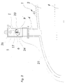
- the manipulator 6 has a number of propeller drives 8a, 8b which are comparatively clearly evident from FIG. 2.
- the manipulator 6 can be moved in the horizontal plane or in height or be moved.
- the state of suspension is set using Trimming bodies 6a, 6b, so that the manipulator 6 is practically weightless in the Liquid F can move.
- the Manipulator 6 has a number of ultrasonic sensors 9 which are attached to the manipulator 6 pivotally held cross beam or crossbar 10 is arranged are. Additionally or alternatively, an ultrasonic group emitter can also be attached to the cross member 10 be arranged.
- the ultrasonic sensors 9 Wall thickness d while driving over the container base 7 on the basis of the difference in transit time between those of the outer wall surface 12 and the inner wall surface 13 reflected ultrasonic waves U detected. Analog can also the wall thickness or thickness d of the vertical container wall 11 are measured, as can be seen from Figure 4a.
- the corresponding measurement signals M are transmitted via a measurement signal line 14 to an evaluation device 15 which is arranged outside the container 1 in a test vehicle 16.
- the respective position of the manipulator 6 is triangulated determined online and, for example, relative to the viewing opening 4.
- To the manipulator 6 has a transmitter 17, in particular an ultrasound transmitter, on, whose signals from two receivers arranged in the container interior 2 18, 19, in particular ultrasound receivers.
- the in the Receivers 18, 19 immersed in liquid F point towards one another and towards the inspection opening 4 a defined distance x or y, so that the position of the manipulator 6 can be determined with respect to the container opening 4.
- the Corresponding position signals P are sent via a control line 20 which together with the measuring line 14 in a manipulator 6 with the test vehicle 16 connecting cable line 21 run to the test vehicle 16.
- the position signals P are on the one hand the evaluation device 15 and on the other hand fed to a control device 22 associated therewith, the is also carried by the test vehicle 16.
- the control device 22 outputs the manipulator 6 in front of a driving program which shows the respective path B, B ' of the manipulator 6 within the liquid F (Fig. 4b and Fig. 5a and 5b).
- the position signals P are then used for remote control and for position correction of the manipulator 6 is used when this from the predetermined path B, B 'deviates.
- This position determination and control is a Movement of the manipulator 6 on any path B, B 'or tracks in one defined distance a to the respective tank wall 7,11.
- the functions the receiver 18, 19 on the one hand and the transmitter carried by the manipulator 6 17 on the other hand can also be replaced, so that the manipulator carries a receiver, while the fixed devices 18, 19 then the Are transmitters.
- FIGS. 4b and 5 show preferred path profiles B, B 'for a measurement of the Wall thickness d of the container wall 11 or the container bottom 7.
- Path B along the container wall 11 is preferably meandering, can measure the wall thickness d of the container bottom 7 both in a meandering shape Lane B (FIG. 5b) as well as in a concentric circle, d. H. helical or spiral path B '(Fig. 5a).
- a spiral path B ' is also in the measurement of the container wall 11 definable.
- a pressure sensor carried by the manipulator 6 23 Information about the immersion depth of the manipulator 6 in the liquid F to the evaluation and / or control device 15, 22.
- Another one sensor system carried by the manipulator 6 in the form of a sonar system 24 is used to identify tank internals or structural parts, such as a heating coil or loop running above the container bottom 7 25 and parts lying inside the container 2.
- the signals M detected by the various sensors 9, 17, 23 and 24 become captured by the evaluation device 15, 22 together with the position signals P. and analyzed by a data processing and recording system as well saved there.
- the measurement signals M are combined with the position signals P correlated, so that the respective measuring point or measuring location has the corresponding Position within the container 1 is assigned.
- the recorded data are subjected to statistical analysis on-line and / or off-line, the greatest and smallest wall thickness d as well as the number, the locations and the areas of the Wall thickness shortfalls can be determined.
- the analysis results are preferably prepared in a color graphic representation such that a Assignment to the respective fault location is established and defects through special Colors, e.g. B. by red marks, on a projection on z. B. the bottom of the container 7 are shown correctly. This is for any repairs to be made expedient.
- results of different test drives can be compared be compared.
- FIG. 3 the manipulator 6 via the lock 5 in the Container interior 2 introduced.
- a cable reel 26 arranged there serves as Cable storage for the cable connection or line 21, via which the manipulator 6 is connected to the test vehicle 16.
Landscapes
- Physics & Mathematics (AREA)
- General Physics & Mathematics (AREA)
- Investigating Or Analyzing Materials By The Use Of Ultrasonic Waves (AREA)
- Examining Or Testing Airtightness (AREA)
- Investigating Or Analyzing Materials By The Use Of Magnetic Means (AREA)
- Length Measuring Devices With Unspecified Measuring Means (AREA)
- Manipulator (AREA)
Abstract
Description
- Fig. 1
- schematisch eine Prüfeinrichtung mit einem Manipulator an zwei unterschiedlichen Positionen oberhalb des Behälterbodens eines flüssigkeitsgefüllten Lagertanks,
- Fig. 2
- einen Ausschnitt aus Fig. 1 in größerem Maßstab mit einem mit Antrieben und Sensoren zur Meß- und Positionserfassung versehenen Manipulator,
- Fig. 3
- einen weiteren Ausschnitt aus Fig. 1 in größerem Maßstab mit einer an eine Behälteröffnung angedockten Schleuse mit darin angeordnetem Manipulator,
- Fig. 4a u. 4b
- einen entlang einer vertikalen Behälterwand verfahrenen Manipulator in Seitenansicht bzw. dessen Bahnverlauf in Draufsicht, und
- Fig. 5a u. 5b
- in Draufsicht einen spiralförmigen bzw. mäanderförmigen Bahnverlauf des Manipulators entlang des Behälterbodens.
- 1
- Behälter/Lagertank
- 2
- Behälterinnenraum
- 3
- Tankzugang
- 4
- Besichtigungsöffnung
- 5
- Schleuse
- 6
- Manipulator
- 6a,b
- Trimmkörper
- 7
- Behälterboden
- 8a,b
- Antrieb
- 9
- Prüfsensor
- 10
- Querholm
- 11
- Behälterwand
- 12,13
- Wandoberfläche
- 14
- Messleitung
- 15
- Auswertevorrichtung
- 16
- Prüffahrzeug
- 17
- Positionssensor
- 18,19
- Sende-/Empfangsvorrichtung
- 20
- Prüfleitung
- 21
- Kabelverbindung
- 22
- Steuerungsvorrichtung
- 23
- Drucksensor
- 24
- Sonaranlage
- 25
- Heizschlange
- 26
- Kabelrolle/-speicher
- a,x,y
- Abstand
- d
- Wanddicke
- B,B'
- Bahn/-verlauf
- F
- Flüssigkeit
- I
- Inertgas
- U
- Ultraschall/-welle
Claims (16)
- Verfahren zum Prüfen eines flüssigkeitsgefüllten Behälters (1), insbesondere eines Lagertanks, bei dem ein eine Anzahl von Prüfsensoren (9,17,23,24) aufweisender Manipulator (6) in der Flüssigkeit (F) bewegt wird, und bei dem von der Behälterwand (7,11) reflektierte und vom Manipulator (6) empfangene Meßsignale (M) mit Positionssignalen (P) korreliert werden, die von einer im Behälterinnenraum (2) an einer definierten Position angeordneten Sende- oder Empfangsvorrichtung (18,19) erzeugt werden, wobei der Manipulator (6) auf einer definierten Bahn (B,B') und zur Behälterwand (7,11) beabstandet an dieser entlang bewegt wird.
- Verfahren nach Anspruch 1, bei dem die Bewegung des Manipulators (6) entlang der definierten Bahn (B,B') anhand der Positionssignale (P) gesteuert wird.
- Verfahren nach Anspruch 1 oder 2, bei dem der Manipulator (6) und die oder jede Sende- und Empfangseinrichtung (18,19) in den Behälterinnenraum (2) durch eine Behälteröffnung (4) eingeführt wird, zu der in definiertem Abstand (y) die jeweilige Sende- und Empfangseinrichtung (18,19) positioniert wird.
- Verfahren nach einem der Ansprüche 1 bis 3, bei dem mittels Ultraschall die Wanddicke (d) des Behälters (1), insbesondere des Behälterbodens (7), geprüft wird.
- Verfahren nach einem der Ansprüche 1 bis 4, bei dem der Manipulator (6) zur Positionsbestimmung einen Sensor (17) mitführt, der die Positionssignale (P) von mindestens zwei in einem definierten Abstand (x) zueinander angeordneten Sende- und Empfangseinrichtungen (18,19) empfängt.
- Verfahren nach einem der Ansprüche 1 bis 5, bei dem behälterinterne Markierungen erfaßt und zur Ortskorrektur der mit den Positionssignalen (P) korrelierten Meßsignale (M) herangezogen werden.
- Einrichtung zur zerstörungsfreien Prüfung eines flüssigkeitsgefüllten Behälters (1), insbesondere eines Lagertanks, mit einem ferngesteuerten Manipulator (6), der einen Antrieb (8) und eine Anzahl von Prüfsensoren (9) sowie einen Positionssensor (17) aufweist, der von einer im Behälterinnenraum (2) an einer definierten Position angeordneten Sende- und/oder Empfangsvorrichtungen (18,19) Positionssignale (P) empfängt, und mit einer Auswertevorrichtung (15,22), die anhand von mittels der Prüfsensoren (9) erfaßten und mit den Positionssignalen (P) korrelierten Meßsignalen (M) den Zustand der oder jeder Behälterwand (7,11) positionsgenau ermittelt.
- Einrichtung nach Anspruch 7, bei der ein erster Antrieb (8a) zur Bewegung des Manipulators (6) in horizontaler Richtung und ein zweiter Antrieb (8b) zu dessen Bewegung in vertikaler Richtung vorgesehen sind.
- Einrichtung nach Anspruch 7 oder 8, bei der die Prüfsensoren (9) schwenkbar am Manipulator (6) angeordnet sind.
- Einrichtung nach einem der Ansprüche 7 bis 9, bei der der Manipulator (6) eine Sonaranlage (24) zur Ortung von behälterinternen Hindernissen (25) aufweist.
- Einrichtung nach einem der Ansprüche 7 bis 10, mit einer auf eine Behälteröffnung (4) aufsetzbaren Schleuse (5), über die der Manipulator (6) sowie die Sende- und/oder Empfangseinrichtung (18,19) in den Behälter (2) einbringbar ist.
- Einrichtung nach einem der Ansprüche 7 bis 11, bei der ein Ultraschallgruppenstrahler als Prüfsensoren (9) vorgesehen ist.
- Einrichtung nach einem der Ansprüche 7 bis 12, bei der ein Sender als Positionssensor (17) vorgesehen ist.
- Einrichtung nach einem der Ansprüche 7 bis 13, bei der am Manipulator (6) ein Drucksensor (23) angeordnet ist.
- Einrichtung nach einem der Ansprüche 7 bis 14, bei der der Manipulator (6) Trimmmittel (6a,6b) aufweist, mit denen ein Schwebezustand des Manipulators (6) in der Flüssigkeit (F) einstellbar ist.
- Einrichtung nach einem der Ansprüche 7 bis 15, bei der der Manipulator (6) über eine Meß- und/oder Steuerleitungen (14,20) umfassende Kabelverbindung (21) an die außerhalb des Behälters (2) vorgesehene Auswertevorrichtung (15,22) angeschlossen ist.
Applications Claiming Priority (4)
| Application Number | Priority Date | Filing Date | Title |
|---|---|---|---|
| DE19905087 | 1999-01-29 | ||
| DE19905087 | 1999-01-29 | ||
| DE19916671A DE19916671A1 (de) | 1999-01-29 | 1999-04-14 | Verfahren und Vorrichtung zum Prüfen eines flüssigkeitsgefüllten Behälters |
| DE19916671 | 1999-04-14 |
Publications (3)
| Publication Number | Publication Date |
|---|---|
| EP1024351A2 true EP1024351A2 (de) | 2000-08-02 |
| EP1024351A3 EP1024351A3 (de) | 2002-01-02 |
| EP1024351B1 EP1024351B1 (de) | 2004-12-01 |
Family
ID=26051727
Family Applications (1)
| Application Number | Title | Priority Date | Filing Date |
|---|---|---|---|
| EP00101826A Expired - Lifetime EP1024351B1 (de) | 1999-01-29 | 2000-01-29 | Verfahren und Einrichtung zum Prüfen eines flüssigkeitsgefüllten Behälters |
Country Status (4)
| Country | Link |
|---|---|
| EP (1) | EP1024351B1 (de) |
| AT (1) | ATE284031T1 (de) |
| DE (1) | DE50008788D1 (de) |
| ES (1) | ES2232334T3 (de) |
Cited By (1)
| Publication number | Priority date | Publication date | Assignee | Title |
|---|---|---|---|---|
| EP1243351A3 (de) * | 2001-03-22 | 2004-01-21 | Bruno Falkenstein GmbH | Reinigungssystem und Verfahren zur Reinigung von Heizöl |
Family Cites Families (7)
| Publication number | Priority date | Publication date | Assignee | Title |
|---|---|---|---|---|
| US4505874A (en) * | 1982-03-08 | 1985-03-19 | Combustion Engineering Co., Inc. | Vessel inspection boom |
| JPS604699A (ja) * | 1983-06-24 | 1985-01-11 | Akihiro Takiguchi | 低温液化ガス用タンクの内部検査法 |
| JPS60201251A (ja) * | 1984-03-26 | 1985-10-11 | Mitsubishi Heavy Ind Ltd | 水中検査装置 |
| JP2535550Y2 (ja) * | 1990-06-05 | 1997-05-14 | 三菱重工業株式会社 | 水中移動型検査装置 |
| US5214616A (en) * | 1991-08-15 | 1993-05-25 | General Electric Company | Nuclear reactor vessel inspection system and method with remote transducer positioning |
| US5456114A (en) * | 1993-04-23 | 1995-10-10 | Panametrics, Inc. | Elastic wave sensing system |
| DE19718386B4 (de) * | 1997-04-30 | 2004-09-23 | Intelligendt Systems & Services Gmbh & Co Kg | Manipulator und Verfahren zum Arbeiten in einem flüssigkeitsgefüllten Behälter |
-
2000
- 2000-01-29 EP EP00101826A patent/EP1024351B1/de not_active Expired - Lifetime
- 2000-01-29 DE DE50008788T patent/DE50008788D1/de not_active Expired - Lifetime
- 2000-01-29 AT AT00101826T patent/ATE284031T1/de active
- 2000-01-29 ES ES00101826T patent/ES2232334T3/es not_active Expired - Lifetime
Cited By (1)
| Publication number | Priority date | Publication date | Assignee | Title |
|---|---|---|---|---|
| EP1243351A3 (de) * | 2001-03-22 | 2004-01-21 | Bruno Falkenstein GmbH | Reinigungssystem und Verfahren zur Reinigung von Heizöl |
Also Published As
| Publication number | Publication date |
|---|---|
| EP1024351B1 (de) | 2004-12-01 |
| EP1024351A3 (de) | 2002-01-02 |
| ATE284031T1 (de) | 2004-12-15 |
| DE50008788D1 (de) | 2005-01-05 |
| ES2232334T3 (es) | 2005-06-01 |
Similar Documents
| Publication | Publication Date | Title |
|---|---|---|
| EP3497016B1 (de) | Unbemanntes luftfahrzeug zur zerstörungsfreien prüfung einer dreidimensionalen struktur | |
| EP0656868B1 (de) | Vorrichtung und verfahren zur steuerung eines containerkranes | |
| DE69510685T2 (de) | Topographiemessung von schlämmen in öltanks | |
| DE69312445T2 (de) | Verfahren und Vorrichtung zur kontinuierlichen zerstörungsfreien Ultraschallprüfung von Eisenbahnschienen | |
| WO2007107242A1 (de) | Verfahren zur ermittlung der position und orientierung einer mess- oder reparatureinrichtung und eine nach dem verfahren arbeitende vorrichtung | |
| EP2932256B1 (de) | Verfahren und system zur handgeführten ultraschallprüfung eines prüfobjekts | |
| DE69424785T2 (de) | Verfahren zur messung der dicke von plattenkonstruktionen und rohren | |
| DE4242541A1 (de) | Vorrichtung zum Orten unterhalb der Erdoberfläche befindlicher Munition | |
| EP2802853A1 (de) | Erfassungssystem zur informationsgewinnung in rohrartigen elementen | |
| DE10246781A1 (de) | Verfahren und Vorrichtung zur dreidimensionalen Vermessung von Objekten | |
| EP0074457B2 (de) | Messverfahren zur Fehlerbestimmung in Schweissnähten | |
| DE102004007830A1 (de) | Verfahren zur Lokalisierung von Fehlstellen und Markiersystem | |
| DE2753635A1 (de) | Verfahren und vorrichtung zur automatischen ermittlung von rissen in schweisszonen, die in umfangsrichtung um ein rohr verlaufen | |
| EP3114472B1 (de) | System und verfahren zur zerstörungsfreien prüfung von metallschmelzschweissverbindungen an dünnwandigen rohren | |
| EP1024351B1 (de) | Verfahren und Einrichtung zum Prüfen eines flüssigkeitsgefüllten Behälters | |
| EP0661528B1 (de) | Bestimmung von Fehlstellen einer Rohrleitung für Fluide, Schallmolch mit Störgeräusch-Abschirmung | |
| DE19916671A1 (de) | Verfahren und Vorrichtung zum Prüfen eines flüssigkeitsgefüllten Behälters | |
| DE3724411A1 (de) | Vorrichtung zum kontinuierlichen messen des fuellstandes | |
| CN119044320B (zh) | 一种焊缝缺陷超声检测实时可视化方法及装置 | |
| Smith et al. | Inspection of nuclear storage tanks using remotely deployed ACFMT. | |
| EP1576363A1 (de) | Ultraschall-prüfger t und verfahren zur auswertung von ultraschallsignalen | |
| EP0191346A2 (de) | Einrichtung zum Bestimmen von Oberflächenrissen | |
| EP0887805B1 (de) | Gerät zum Bestimmen eines Profils entlang der Innenoberfläche eines Rohres | |
| DE19718386A1 (de) | Manipulator und Verfahren zum Arbeiten in einem flüssigkeitsgefüllten Behälter | |
| DE102019116142A1 (de) | Vorrichtung zur tomografischen Ultraschallprüfung einer Innenstruktur einer Metallbramme und Verfahren zur in-situ Qualitätsprüfung von Metallbrammen |
Legal Events
| Date | Code | Title | Description |
|---|---|---|---|
| PUAI | Public reference made under article 153(3) epc to a published international application that has entered the european phase |
Free format text: ORIGINAL CODE: 0009012 |
|
| AK | Designated contracting states |
Kind code of ref document: A2 Designated state(s): AT BE CH CY DE DK ES FI FR GB GR IE IT LI LU MC NL PT SE |
|
| AX | Request for extension of the european patent |
Free format text: AL;LT;LV;MK;RO;SI |
|
| RAP1 | Party data changed (applicant data changed or rights of an application transferred) |
Owner name: ALSTOM AUTOMATION GMBH |
|
| PUAL | Search report despatched |
Free format text: ORIGINAL CODE: 0009013 |
|
| AK | Designated contracting states |
Kind code of ref document: A3 Designated state(s): AT BE CH CY DE DK ES FI FR GB GR IE IT LI LU MC NL PT SE |
|
| AX | Request for extension of the european patent |
Free format text: AL;LT;LV;MK;RO;SI |
|
| RIC1 | Information provided on ipc code assigned before grant |
Free format text: 7G 01N 29/22 A, 7G 01B 17/02 B, 7G 01M 3/24 B |
|
| RAP1 | Party data changed (applicant data changed or rights of an application transferred) |
Owner name: CEGELEC ANLAGEN- UND AUTOMATISIERUNGSTECHNIK GMBH |
|
| 17P | Request for examination filed |
Effective date: 20020611 |
|
| AKX | Designation fees paid |
Free format text: AT BE CH CY DE DK ES FI FR GB GR IE IT LI LU MC NL PT SE |
|
| 17Q | First examination report despatched |
Effective date: 20031105 |
|
| RIN1 | Information on inventor provided before grant (corrected) |
Inventor name: OTTE, HEINZ-JOSEF Inventor name: KREJTSCHI, JUERGEN Inventor name: ROTH, WERNER |
|
| GRAP | Despatch of communication of intention to grant a patent |
Free format text: ORIGINAL CODE: EPIDOSNIGR1 |
|
| GRAS | Grant fee paid |
Free format text: ORIGINAL CODE: EPIDOSNIGR3 |
|
| GRAA | (expected) grant |
Free format text: ORIGINAL CODE: 0009210 |
|
| AK | Designated contracting states |
Kind code of ref document: B1 Designated state(s): AT BE CH CY DE DK ES FI FR GB GR IE IT LI LU MC NL PT SE |
|
| PG25 | Lapsed in a contracting state [announced via postgrant information from national office to epo] |
Ref country code: FI Free format text: LAPSE BECAUSE OF FAILURE TO SUBMIT A TRANSLATION OF THE DESCRIPTION OR TO PAY THE FEE WITHIN THE PRESCRIBED TIME-LIMIT Effective date: 20041201 Ref country code: IE Free format text: LAPSE BECAUSE OF FAILURE TO SUBMIT A TRANSLATION OF THE DESCRIPTION OR TO PAY THE FEE WITHIN THE PRESCRIBED TIME-LIMIT Effective date: 20041201 |
|
| REG | Reference to a national code |
Ref country code: GB Ref legal event code: FG4D Free format text: NOT ENGLISH |
|
| REG | Reference to a national code |
Ref country code: CH Ref legal event code: EP |
|
| REG | Reference to a national code |
Ref country code: IE Ref legal event code: FG4D Free format text: GERMAN |
|
| REF | Corresponds to: |
Ref document number: 50008788 Country of ref document: DE Date of ref document: 20050105 Kind code of ref document: P |
|
| PG25 | Lapsed in a contracting state [announced via postgrant information from national office to epo] |
Ref country code: LU Free format text: LAPSE BECAUSE OF NON-PAYMENT OF DUE FEES Effective date: 20050129 Ref country code: CY Free format text: LAPSE BECAUSE OF FAILURE TO SUBMIT A TRANSLATION OF THE DESCRIPTION OR TO PAY THE FEE WITHIN THE PRESCRIBED TIME-LIMIT Effective date: 20050129 |
|
| PG25 | Lapsed in a contracting state [announced via postgrant information from national office to epo] |
Ref country code: MC Free format text: LAPSE BECAUSE OF NON-PAYMENT OF DUE FEES Effective date: 20050131 Ref country code: BE Free format text: LAPSE BECAUSE OF NON-PAYMENT OF DUE FEES Effective date: 20050131 |
|
| REG | Reference to a national code |
Ref country code: CH Ref legal event code: NV Representative=s name: E. BLUM & CO. PATENTANWAELTE |
|
| PG25 | Lapsed in a contracting state [announced via postgrant information from national office to epo] |
Ref country code: DK Free format text: LAPSE BECAUSE OF FAILURE TO SUBMIT A TRANSLATION OF THE DESCRIPTION OR TO PAY THE FEE WITHIN THE PRESCRIBED TIME-LIMIT Effective date: 20050301 Ref country code: GR Free format text: LAPSE BECAUSE OF FAILURE TO SUBMIT A TRANSLATION OF THE DESCRIPTION OR TO PAY THE FEE WITHIN THE PRESCRIBED TIME-LIMIT Effective date: 20050301 |
|
| REG | Reference to a national code |
Ref country code: SE Ref legal event code: TRGR |
|
| GBT | Gb: translation of ep patent filed (gb section 77(6)(a)/1977) |
Effective date: 20050321 |
|
| REG | Reference to a national code |
Ref country code: ES Ref legal event code: FG2A Ref document number: 2232334 Country of ref document: ES Kind code of ref document: T3 |
|
| REG | Reference to a national code |
Ref country code: IE Ref legal event code: FD4D |
|
| BERE | Be: lapsed |
Owner name: CEGELEC ANLAGEN- UND AUTOMATISIERUNGSTECHNIK G.M.B Effective date: 20050131 |
|
| PLBE | No opposition filed within time limit |
Free format text: ORIGINAL CODE: 0009261 |
|
| STAA | Information on the status of an ep patent application or granted ep patent |
Free format text: STATUS: NO OPPOSITION FILED WITHIN TIME LIMIT |
|
| 26N | No opposition filed |
Effective date: 20050902 |
|
| ET | Fr: translation filed | ||
| REG | Reference to a national code |
Ref country code: CH Ref legal event code: PFA Owner name: CEGELEC ANLAGEN- UND AUTOMATISIERUNGSTECHNIK GMBH Free format text: CEGELEC ANLAGEN- UND AUTOMATISIERUNGSTECHNIK GMBH & CO KG#LYONER STRASSE 9#60256 FRANKFURT AM MAIN (DE) -TRANSFER TO- CEGELEC ANLAGEN- UND AUTOMATISIERUNGSTECHNIK GMBH & CO KG#LYONER STRASSE 9#60256 FRANKFURT AM MAIN (DE) |
|
| BERE | Be: lapsed |
Owner name: *CEGELEC ANLAGEN- UND AUTOMATISIERUNGSTECHNIK G.M. Effective date: 20050131 |
|
| PG25 | Lapsed in a contracting state [announced via postgrant information from national office to epo] |
Ref country code: PT Free format text: LAPSE BECAUSE OF NON-PAYMENT OF DUE FEES Effective date: 20050501 |
|
| PGFP | Annual fee paid to national office [announced via postgrant information from national office to epo] |
Ref country code: SE Payment date: 20110121 Year of fee payment: 12 Ref country code: AT Payment date: 20110120 Year of fee payment: 12 |
|
| PGFP | Annual fee paid to national office [announced via postgrant information from national office to epo] |
Ref country code: ES Payment date: 20110121 Year of fee payment: 12 |
|
| REG | Reference to a national code |
Ref country code: SE Ref legal event code: EUG |
|
| PG25 | Lapsed in a contracting state [announced via postgrant information from national office to epo] |
Ref country code: SE Free format text: LAPSE BECAUSE OF NON-PAYMENT OF DUE FEES Effective date: 20120130 |
|
| REG | Reference to a national code |
Ref country code: AT Ref legal event code: MM01 Ref document number: 284031 Country of ref document: AT Kind code of ref document: T Effective date: 20120129 |
|
| PG25 | Lapsed in a contracting state [announced via postgrant information from national office to epo] |
Ref country code: AT Free format text: LAPSE BECAUSE OF NON-PAYMENT OF DUE FEES Effective date: 20120129 |
|
| PG25 | Lapsed in a contracting state [announced via postgrant information from national office to epo] |
Ref country code: ES Free format text: LAPSE BECAUSE OF NON-PAYMENT OF DUE FEES Effective date: 20120130 |
|
| REG | Reference to a national code |
Ref country code: ES Ref legal event code: FD2A Effective date: 20131031 |
|
| PGFP | Annual fee paid to national office [announced via postgrant information from national office to epo] |
Ref country code: IT Payment date: 20150121 Year of fee payment: 16 Ref country code: CH Payment date: 20150123 Year of fee payment: 16 |
|
| PGFP | Annual fee paid to national office [announced via postgrant information from national office to epo] |
Ref country code: GB Payment date: 20150123 Year of fee payment: 16 |
|
| REG | Reference to a national code |
Ref country code: FR Ref legal event code: PLFP Year of fee payment: 17 |
|
| REG | Reference to a national code |
Ref country code: CH Ref legal event code: PL |
|
| GBPC | Gb: european patent ceased through non-payment of renewal fee |
Effective date: 20160129 |
|
| PG25 | Lapsed in a contracting state [announced via postgrant information from national office to epo] |
Ref country code: CH Free format text: LAPSE BECAUSE OF NON-PAYMENT OF DUE FEES Effective date: 20160131 Ref country code: GB Free format text: LAPSE BECAUSE OF NON-PAYMENT OF DUE FEES Effective date: 20160129 Ref country code: LI Free format text: LAPSE BECAUSE OF NON-PAYMENT OF DUE FEES Effective date: 20160131 |
|
| PG25 | Lapsed in a contracting state [announced via postgrant information from national office to epo] |
Ref country code: IT Free format text: LAPSE BECAUSE OF NON-PAYMENT OF DUE FEES Effective date: 20160129 |
|
| REG | Reference to a national code |
Ref country code: FR Ref legal event code: PLFP Year of fee payment: 18 |
|
| REG | Reference to a national code |
Ref country code: FR Ref legal event code: PLFP Year of fee payment: 19 |
|
| PGFP | Annual fee paid to national office [announced via postgrant information from national office to epo] |
Ref country code: DE Payment date: 20180117 Year of fee payment: 19 |
|
| PGFP | Annual fee paid to national office [announced via postgrant information from national office to epo] |
Ref country code: FR Payment date: 20190123 Year of fee payment: 20 Ref country code: NL Payment date: 20190122 Year of fee payment: 20 |
|
| REG | Reference to a national code |
Ref country code: DE Ref legal event code: R119 Ref document number: 50008788 Country of ref document: DE |
|
| PG25 | Lapsed in a contracting state [announced via postgrant information from national office to epo] |
Ref country code: DE Free format text: LAPSE BECAUSE OF NON-PAYMENT OF DUE FEES Effective date: 20190801 |
|
| REG | Reference to a national code |
Ref country code: NL Ref legal event code: MK Effective date: 20200128 |