EP1024574A2 - Méthode pour connecter un transformateur au réseau alternatif ainsi qu'un circuit pour la mise en oeuvre de ce procédé - Google Patents
Méthode pour connecter un transformateur au réseau alternatif ainsi qu'un circuit pour la mise en oeuvre de ce procédé Download PDFInfo
- Publication number
- EP1024574A2 EP1024574A2 EP00100965A EP00100965A EP1024574A2 EP 1024574 A2 EP1024574 A2 EP 1024574A2 EP 00100965 A EP00100965 A EP 00100965A EP 00100965 A EP00100965 A EP 00100965A EP 1024574 A2 EP1024574 A2 EP 1024574A2
- Authority
- EP
- European Patent Office
- Prior art keywords
- transformer
- pulse converter
- voltage
- converter
- network
- Prior art date
- Legal status (The legal status is an assumption and is not a legal conclusion. Google has not performed a legal analysis and makes no representation as to the accuracy of the status listed.)
- Granted
Links
Images

Classifications
-
- H—ELECTRICITY
- H02—GENERATION; CONVERSION OR DISTRIBUTION OF ELECTRIC POWER
- H02H—EMERGENCY PROTECTIVE CIRCUIT ARRANGEMENTS
- H02H9/00—Emergency protective circuit arrangements for limiting excess current or voltage without disconnection
- H02H9/001—Emergency protective circuit arrangements for limiting excess current or voltage without disconnection limiting speed of change of electric quantities, e.g. soft switching on or off
- H02H9/002—Emergency protective circuit arrangements for limiting excess current or voltage without disconnection limiting speed of change of electric quantities, e.g. soft switching on or off limiting inrush current on switching on of inductive loads subjected to remanence, e.g. transformers
-
- B—PERFORMING OPERATIONS; TRANSPORTING
- B60—VEHICLES IN GENERAL
- B60L—PROPULSION OF ELECTRICALLY-PROPELLED VEHICLES; SUPPLYING ELECTRIC POWER FOR AUXILIARY EQUIPMENT OF ELECTRICALLY-PROPELLED VEHICLES; ELECTRODYNAMIC BRAKE SYSTEMS FOR VEHICLES IN GENERAL; MAGNETIC SUSPENSION OR LEVITATION FOR VEHICLES; MONITORING OPERATING VARIABLES OF ELECTRICALLY-PROPELLED VEHICLES; ELECTRIC SAFETY DEVICES FOR ELECTRICALLY-PROPELLED VEHICLES
- B60L2200/00—Type of vehicles
- B60L2200/26—Rail vehicles
Definitions
- the invention relates to a method and an arrangement for connecting a Transformer to an AC voltage network, with at least one primary winding of the Transformer connected to the AC network via a circuit breaker and a pulse converter suitable for four-quadrant operation to at least one Secondary winding of the transformer can be connected as well as on a Circuit arrangement for performing the method.
- the invention is particularly for Railway applications (electric rail vehicles) suitable.
- the defined switching on of mechanical switching devices within one Grid period time fails due to the spread of the switching times of the switching devices largely determines the ambient temperature, aging and type spread become. Furthermore, due to the unknown remanence of the transformer given additional inaccuracies, which the possibility of a network synchronous Difficult to turn on.
- the invention has for its object a method for connecting a Specify transformer to an AC network that avoids a switch-on rush or at least limited its impact. Furthermore, a circuit arrangement for Perform the procedure.
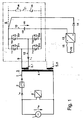
- a single-phase AC voltage network 1 shows a converter arrangement connected to a single-phase AC voltage network, as is usually used in electric rail vehicles (single-phase rail applications).
- a single-phase AC voltage network 1 can be seen, which is connected to a primary winding 4 of a transformer 3 via a power switch 2.
- the transformer 3 has a plurality of secondary windings, of which a first secondary winding 5.1 and an nth secondary winding 5.n are designated. Other existing secondary windings are not shown for reasons of clarity.
- a primary-side voltage converter 6 detects the mains voltage U N.
- a current transformer 7 arranged between the circuit breaker 2 and the primary winding 4 detects the mains current i N.
- the alternating connections of a self-commutated pulse converter 8 are connected to the secondary winding 5.1 of the transformer 3, a switch 9 for switching the pulse converter 8 on / off preferably being interposed.
- the pulse converter 8 can carry out an energy exchange in all four quadrants and, in a generally known manner, has four branches arranged in a bridge circuit, each with an ignitable and erasable main valve T11 or T21 or T12 or T22, with each main valve having a reverse power diode D11 or D21 or D12 or D22 is antiparallel.
- the DC connections of the bridge circuit are also connected in a generally known manner to an intermediate circuit 10 with an intermediate circuit capacitor CD and, if appropriate, to an overvoltage limiting branch 11 with a resistor R UB and a series controllable valve T UB.
- an overvoltage limiting branch 11 with a resistor R UB and a series controllable valve T UB.
- a voltage varistor can also be provided.
- the intermediate circuit voltage is designated U D.
- An inverter (not shown) (see number 39 in FIG. 2) is usually connected to the intermediate circuit 10 and serves to supply at least one drive motor of a rail vehicle.
- a current converter 12 is used to detect the pulse converter input current i 1 flowing between the secondary winding 5.1 and the alternating connections of the pulse converter 8.
- a precharging device 13 - in 1 a DC / DC converter - provided, which on the output side via a decoupling diode 14 (protection against feedback) with the intermediate circuit 10 and on the input side via a switch 15 with a DC voltage source 16, preferably one Battery, is connected.
- a DC voltage source 16 preferably one Battery
- FIG Matching transformer with downstream diode precharging device 43 be used. This precharging device 43 is on the input side via a switch 44 an AC voltage source 45 can be supplied.
- the two voltage converters 28, 29 are used to detect the voltages of interest.
- the currents flowing in the phases are detected by three current transformers 30, 31, 32.
- Three current transformers 40, 41, 42 are used to detect the pulse converter input currents i 1 , i 2 , i 3 .
- the pulse converter 33 can carry out an energy exchange in all four quadrants.
- the intermediate circuit of the pulse converter 33 with the intermediate circuit capacitor CD is denoted by number 37 and the overvoltage limiting branch with the structural components R UB and T UB explained under FIG. 1 is denoted by number 38. It is indicated that the DC connections of the pulse converter 33 are connected to an inverter 39.
- the transformer 3 can be switched on to the AC voltage network 1 using three different methods according to the invention.
- rush compensation is completely avoided in terms of control technology.
- second and third methods there is a switch-on rush, however, the same leather occurring in the mains current i N is rapidly reduced in a defined manner by targeted influence on the secondary side with the aid of the pulse converter.
- control flow according to the first method is carried out according to the following steps performed:
- the intermediate circuit 10 is precharged in a first step.
- the precharging device 13 or 43 is switched on for this at the latest after the circuit breaker 2 has been switched on.
- the precharging device 13 or 43 charges the intermediate circuit 10 to an intermediate circuit voltage U D which is above the peak value of the mains voltage U N.
- Pulse-width-modulated intermediate circuit voltage blocks are connected to the secondary winding 5.1 by the periodically clocking pulse converter 8.
- the pulse width modulation is carried out as a function of the line voltage U N (line synchronous, line voltage-guided) according to a generally known comparison method.
- the magnetization current curve, ie the curve of the pulse converter input current i 1 is measured via the current transformer 12 and the width of the intermediate circuit voltage blocks during the positive and negative mains voltage half-wave is influenced in a targeted manner by current control in such a way that occurring direct links (direct current components) are corrected.
- the pulse converter 8 is preferably enabled at 90 ° before or after the zero crossing of the mains voltage U N. In the case of transformers with high remanence, the pulse converter 8 is expediently enabled immediately after the mains voltage U N has passed zero, in order to achieve a defined induction within a half cycle of the mains voltage U N.
- the beginning saturation state is either recognized by the exceeding of a current threshold (pulse converter input current i 1 ) or alternatively by the progressive change in the steepness of the magnetization current curve (di 1 / dt).
- a current threshold pulse converter input current i 1
- the current value pulse converter input current i 1
- the pulsed voltage applied to the secondary winding 5.1 is modulated analogously to the profile of the mains voltage U N.
- the steady state is reached and in a third step the circuit breaker 2 can be enabled, which means that the circuit breaker 2 connects the transformer 3 to the AC network 1 after its own time.
- the pulse converter is expedient after the network connection has been established locked until it is released for its main task, so as not to cause unnecessary losses produce.
- control flow according to the second method is carried out according to the following steps performed:
- the intermediate circuit 10 is precharged in a first step way explained for the first method.
- the pulse converter 8 After the intermediate circuit 10 has been precharged, the pulse converter 8 initially remains blocked. The switch 9 is inserted and in a second font the circuit breaker 2 is enabled to be switched on. After the switch contacts of the circuit breaker 2 are closed, a different compensation process occurs depending on the instant of switching. Immediately after the circuit breaker 2 has been switched on, the pulse converter 8 is released.
- the switching on of the circuit breaker 2 can be detected, for example, by feedback from the circuit breaker 2 itself or, alternatively, can be detected by the occurrence of a mains atom i N with the aid of the current transformer 7.
- the mains atom i N measured by the current transformer 7 As a converter controlled variable, it is possible to reduce the direct links (DC components) occurring in the mains current i N from the pulse converter 8 in a few half-waves of the mains voltage U N as a result of the switch-on rush. This is done by impressing different voltage time areas for the respective half-wave of the mains voltage U N.
- the intermediate circuit capacitor CD serves to temporarily store the magnetic energy.
- the third method uses the DC link 10 is not charged before the circuit breaker 2 is switched on. As a result the precharging device 13 or 43 is unnecessary. The charging of the DC link 10 rather takes place from the primary side of the transformer 3, as from the following Explanation is evident.
- the control flow according to the third method is after following steps:
- the circuit breaker 2 is closed in a first step. With the insertion of the circuit breaker 2, the charging of the secondary side connected to the intermediate circuit starts immediately 10. The load vibration to the intermediate circuit capacitor CD via the transformer Great inductors, the switch 9 and the reverse power diodes of the pulse current converter 8. The overshoot of the line voltage U N is present in the circuit (and unavoidable) ohmic resistances and in many cases sufficiently attenuated by the filter effect of transformer leakage reactance, additional inductance (if available) and DC link capacitor CD.
- the overvoltage limitation branch 11 takes over the excess energy and thus limits the overshooting intermediate circuit voltage U D to permissible values. Due to the load on the secondary side when the transformer is switched on, the common elements that occur are lower than when the secondary winding is not loaded, that is to say when the switch 9 is open.
- the third step is analogous to the third step of the second method explained above.
Landscapes
- Engineering & Computer Science (AREA)
- Power Engineering (AREA)
- Rectifiers (AREA)
- Ac-Ac Conversion (AREA)
- Emergency Protection Circuit Devices (AREA)
- Protection Of Transformers (AREA)
Applications Claiming Priority (2)
| Application Number | Priority Date | Filing Date | Title |
|---|---|---|---|
| DE19903131 | 1999-01-27 | ||
| DE19903131A DE19903131A1 (de) | 1999-01-27 | 1999-01-27 | Verfahren zum Zuschalten eines Transformators an ein Wechselspannungsnetz und Schaltungsanordnung zur Durchführung des Verfahrens |
Publications (3)
| Publication Number | Publication Date |
|---|---|
| EP1024574A2 true EP1024574A2 (fr) | 2000-08-02 |
| EP1024574A3 EP1024574A3 (fr) | 2002-03-13 |
| EP1024574B1 EP1024574B1 (fr) | 2006-03-22 |
Family
ID=7895508
Family Applications (1)
| Application Number | Title | Priority Date | Filing Date |
|---|---|---|---|
| EP00100965A Expired - Lifetime EP1024574B1 (fr) | 1999-01-27 | 2000-01-19 | Procédé pour connecter un transformateur au réseau de tension alternative ainsi qu'un circuit pour la mise en oeuvre de ce procédé |
Country Status (3)
| Country | Link |
|---|---|
| EP (1) | EP1024574B1 (fr) |
| AT (1) | ATE321370T1 (fr) |
| DE (2) | DE19903131A1 (fr) |
Cited By (4)
| Publication number | Priority date | Publication date | Assignee | Title |
|---|---|---|---|---|
| FR2901431A1 (fr) * | 2006-05-18 | 2007-11-23 | Converteam Sas Soc Par Actions | Circuit de conversion de courant. |
| FR2926259A1 (fr) * | 2008-01-15 | 2009-07-17 | Alstom Transport Sa | Procede et dispositif de connexion d'un transformateur de vehicule ferroviaire a une catenaire. |
| EP3010104A1 (fr) | 2014-10-17 | 2016-04-20 | ABB Technology AG | Prémagnétisation d'un transformateur MMC connecté |
| US11876446B2 (en) | 2021-05-28 | 2024-01-16 | Thermo King Llc | Power converter |
Families Citing this family (4)
| Publication number | Priority date | Publication date | Assignee | Title |
|---|---|---|---|---|
| DE102005011554A1 (de) * | 2005-03-14 | 2006-09-21 | Siemens Ag | Verfahren und Vorrichtung zur Kompensation eines Gleichspannungsanteils an einer Primärwicklung eines Transformators |
| DE102007042528B4 (de) * | 2007-09-07 | 2018-06-14 | Sew-Eurodrive Gmbh & Co Kg | System und Verfahren zur Vorladung eines Zwischenkreiskondensators |
| DE102009019341A1 (de) | 2009-04-30 | 2010-11-18 | Bombardier Transportation Gmbh | Verfahren und Vorrichtung zum Schalten einer Transformatoreinrichtung eines Schienenfahrzeugs an eine Wechselspannung liefernde Energieversorgungseinrichtung |
| DE102010030693A1 (de) | 2010-06-30 | 2012-01-05 | Bayerische Motoren Werke Aktiengesellschaft | Schaltungsanordnung für ein Kraftfahrzeug und Verfahren zum Betreiben der Schaltungsanordnung |
Family Cites Families (5)
| Publication number | Priority date | Publication date | Assignee | Title |
|---|---|---|---|---|
| DE2424716C3 (de) * | 1974-05-21 | 1980-12-04 | Transformatoren Union Ag, 7000 Stuttgart | Anordnung zur völligen oder teilweisen Unterdrückung des Einschaltstromstoßes von Lokomotivtransformatoren |
| US4175276A (en) * | 1977-10-25 | 1979-11-20 | General Electric Company | Transformer inrush current detector |
| DE4108106A1 (de) * | 1991-03-13 | 1992-09-17 | Fraunhofer Ges Forschung | Verfahren und vorrichtung zur reduzierung des einschaltstromstosses beim betreiben einer induktivitaetsbehafteten last |
| DE4309484C1 (de) * | 1993-03-24 | 1994-02-24 | Fraunhofer Ges Forschung | Verfahren zum Unterdrücken eines Einschaltstromstoßes beim Anschalten eines Leistungstransformators |
| DE19734272C1 (de) * | 1997-08-07 | 1999-01-07 | Siemens Ag | Verfahren und Vorrichtung zur Ausregelung von Verzerrungen im Magnetisierungsstrom eines Transformators, der mit einem selbstgeführten Stromrichter mit abschaltbarem Leistungshalbleiterschalter verknüpft ist |
-
1999
- 1999-01-27 DE DE19903131A patent/DE19903131A1/de not_active Withdrawn
-
2000
- 2000-01-19 AT AT00100965T patent/ATE321370T1/de not_active IP Right Cessation
- 2000-01-19 EP EP00100965A patent/EP1024574B1/fr not_active Expired - Lifetime
- 2000-01-19 DE DE50012419T patent/DE50012419D1/de not_active Expired - Lifetime
Cited By (6)
| Publication number | Priority date | Publication date | Assignee | Title |
|---|---|---|---|---|
| FR2901431A1 (fr) * | 2006-05-18 | 2007-11-23 | Converteam Sas Soc Par Actions | Circuit de conversion de courant. |
| FR2926259A1 (fr) * | 2008-01-15 | 2009-07-17 | Alstom Transport Sa | Procede et dispositif de connexion d'un transformateur de vehicule ferroviaire a une catenaire. |
| EP3010104A1 (fr) | 2014-10-17 | 2016-04-20 | ABB Technology AG | Prémagnétisation d'un transformateur MMC connecté |
| WO2016058794A1 (fr) | 2014-10-17 | 2016-04-21 | Abb Technology Ag | Pré-aimantation de transformateur connecté mmc |
| US10305274B2 (en) | 2014-10-17 | 2019-05-28 | Abb Schweiz Ag | Pre-magnetizing a transformer connected to a modular multilevel power converter |
| US11876446B2 (en) | 2021-05-28 | 2024-01-16 | Thermo King Llc | Power converter |
Also Published As
| Publication number | Publication date |
|---|---|
| DE50012419D1 (de) | 2006-05-11 |
| ATE321370T1 (de) | 2006-04-15 |
| EP1024574A3 (fr) | 2002-03-13 |
| DE19903131A1 (de) | 2000-08-03 |
| EP1024574B1 (fr) | 2006-03-22 |
Similar Documents
| Publication | Publication Date | Title |
|---|---|---|
| EP2282399B1 (fr) | Convertisseur statique et procédé de démarrage du convertisseur | |
| EP1311058B1 (fr) | Convertisseur de frequence | |
| WO2017125204A1 (fr) | Convertisseur continu/continu bidirectionnel et procédé de charge du condensateur de circuit intermédiaire d'un convertisseur continu/continu de la batterie basse tension | |
| EP2458725A1 (fr) | Système convertisseur d'énergie électrique et procédé de son fonctionnement | |
| DE102012223591A1 (de) | Vorrichtung und Verfahren zum Laden eines elektrischen Energiespeichers aus einer dreiphasigen Wechselspannungsquelle | |
| DE2165959A1 (de) | Verfahren zur steuerung eines stromrichters mit steuerbaren stromrichterventilen und ihnen zugeordneten loescheinrichtungen | |
| DE102014209653A1 (de) | Ansteuervorrichtung, Elektromaschine und Verfahren | |
| EP3290254A1 (fr) | Convertisseur de reseau de bord bidirectionnel et son procede de fonctionnement | |
| EP1024574B1 (fr) | Procédé pour connecter un transformateur au réseau de tension alternative ainsi qu'un circuit pour la mise en oeuvre de ce procédé | |
| EP1245074A1 (fr) | Systeme redresseur triphase a impulsions, a circuit intermediaire et a faible reaction sur le reseau, dote d'une large plage de reglage de la tension de sortie | |
| WO2016034233A1 (fr) | Procédé de contrôle d'un élément semi-conducteur haute puissance | |
| EP3462586A1 (fr) | Prècharge d'un convertisseur statique à circuit intermédiaire à tension continue au moyen d'une alimentation en énergie auxiliaire | |
| EP2733837A1 (fr) | Convertisseur | |
| EP3602762B1 (fr) | Onduleur | |
| DE3035305C2 (de) | Wechselrichterschaltung für einen Dreiphasen-Synchronmotor | |
| DE102019105310B4 (de) | Elektrischer Antrieb | |
| EP0300392A2 (fr) | Circuit de redressement pour alimenter un circuit de circulation intermédiaire en courant continu | |
| DE102020106349A1 (de) | Elektrische Schaltungsanordnung und Kraftfahrzeug | |
| WO2005112244A1 (fr) | Procede de commande et ensemble circuit pour un redresseur | |
| EP3167297B1 (fr) | Circuit de contrôle d'un élément semi-conducteur haute puissance | |
| DE112018007147T5 (de) | Gleichrichter-Schaltungsvorrichtung | |
| DE4325275A1 (de) | Stromrichterschaltung zur Speisung eines Gleichspannungszwischenkreises | |
| DE102009008048A1 (de) | Verfahren zur Regelung eines selbstgeführten Netzstromrichters eines Spannungszwischenkreis-Umrichters | |
| DE691729C (de) | Verfahren und Einrichtung zum Betrieb einer Gleichstromfernleitung | |
| WO2020058445A1 (fr) | Dispositif de commande conçu pour un onduleur, onduleur conçu pour un véhicule, véhicule et procédé pour faire fonctionner un onduleur |
Legal Events
| Date | Code | Title | Description |
|---|---|---|---|
| PUAI | Public reference made under article 153(3) epc to a published international application that has entered the european phase |
Free format text: ORIGINAL CODE: 0009012 |
|
| AK | Designated contracting states |
Kind code of ref document: A2 Designated state(s): AT BE CH CY DE DK ES FI FR GB GR IE IT LI LU MC NL PT SE |
|
| AX | Request for extension of the european patent |
Free format text: AL;LT;LV;MK;RO;SI |
|
| PUAL | Search report despatched |
Free format text: ORIGINAL CODE: 0009013 |
|
| AK | Designated contracting states |
Kind code of ref document: A3 Designated state(s): AT BE CH CY DE DK ES FI FR GB GR IE IT LI LU MC NL PT SE |
|
| AX | Request for extension of the european patent |
Free format text: AL;LT;LV;MK;RO;SI |
|
| 17P | Request for examination filed |
Effective date: 20020425 |
|
| AKX | Designation fees paid |
Free format text: AT BE CH CY DE DK ES FI FR GB GR IE IT LI LU MC NL PT SE |
|
| GRAP | Despatch of communication of intention to grant a patent |
Free format text: ORIGINAL CODE: EPIDOSNIGR1 |
|
| GRAS | Grant fee paid |
Free format text: ORIGINAL CODE: EPIDOSNIGR3 |
|
| GRAA | (expected) grant |
Free format text: ORIGINAL CODE: 0009210 |
|
| AK | Designated contracting states |
Kind code of ref document: B1 Designated state(s): AT BE CH CY DE DK ES FI FR GB GR IE IT LI LU MC NL PT SE |
|
| PG25 | Lapsed in a contracting state [announced via postgrant information from national office to epo] |
Ref country code: IT Free format text: LAPSE BECAUSE OF FAILURE TO SUBMIT A TRANSLATION OF THE DESCRIPTION OR TO PAY THE FEE WITHIN THE PRESCRIBED TIME-LIMIT;WARNING: LAPSES OF ITALIAN PATENTS WITH EFFECTIVE DATE BEFORE 2007 MAY HAVE OCCURRED AT ANY TIME BEFORE 2007. THE CORRECT EFFECTIVE DATE MAY BE DIFFERENT FROM THE ONE RECORDED. Effective date: 20060322 Ref country code: NL Free format text: LAPSE BECAUSE OF FAILURE TO SUBMIT A TRANSLATION OF THE DESCRIPTION OR TO PAY THE FEE WITHIN THE PRESCRIBED TIME-LIMIT Effective date: 20060322 Ref country code: IE Free format text: LAPSE BECAUSE OF FAILURE TO SUBMIT A TRANSLATION OF THE DESCRIPTION OR TO PAY THE FEE WITHIN THE PRESCRIBED TIME-LIMIT Effective date: 20060322 Ref country code: GB Free format text: LAPSE BECAUSE OF FAILURE TO SUBMIT A TRANSLATION OF THE DESCRIPTION OR TO PAY THE FEE WITHIN THE PRESCRIBED TIME-LIMIT Effective date: 20060322 |
|
| REG | Reference to a national code |
Ref country code: GB Ref legal event code: FG4D Free format text: NOT ENGLISH |
|
| REG | Reference to a national code |
Ref country code: CH Ref legal event code: EP |
|
| REG | Reference to a national code |
Ref country code: IE Ref legal event code: FG4D Free format text: LANGUAGE OF EP DOCUMENT: GERMAN |
|
| REF | Corresponds to: |
Ref document number: 50012419 Country of ref document: DE Date of ref document: 20060511 Kind code of ref document: P |
|
| PG25 | Lapsed in a contracting state [announced via postgrant information from national office to epo] |
Ref country code: DK Free format text: LAPSE BECAUSE OF FAILURE TO SUBMIT A TRANSLATION OF THE DESCRIPTION OR TO PAY THE FEE WITHIN THE PRESCRIBED TIME-LIMIT Effective date: 20060622 Ref country code: SE Free format text: LAPSE BECAUSE OF FAILURE TO SUBMIT A TRANSLATION OF THE DESCRIPTION OR TO PAY THE FEE WITHIN THE PRESCRIBED TIME-LIMIT Effective date: 20060622 |
|
| PG25 | Lapsed in a contracting state [announced via postgrant information from national office to epo] |
Ref country code: ES Free format text: LAPSE BECAUSE OF FAILURE TO SUBMIT A TRANSLATION OF THE DESCRIPTION OR TO PAY THE FEE WITHIN THE PRESCRIBED TIME-LIMIT Effective date: 20060703 |
|
| PG25 | Lapsed in a contracting state [announced via postgrant information from national office to epo] |
Ref country code: PT Free format text: LAPSE BECAUSE OF FAILURE TO SUBMIT A TRANSLATION OF THE DESCRIPTION OR TO PAY THE FEE WITHIN THE PRESCRIBED TIME-LIMIT Effective date: 20060822 |
|
| NLV1 | Nl: lapsed or annulled due to failure to fulfill the requirements of art. 29p and 29m of the patents act | ||
| GBV | Gb: ep patent (uk) treated as always having been void in accordance with gb section 77(7)/1977 [no translation filed] |
Effective date: 20060322 |
|
| REG | Reference to a national code |
Ref country code: IE Ref legal event code: FD4D |
|
| PLBE | No opposition filed within time limit |
Free format text: ORIGINAL CODE: 0009261 |
|
| STAA | Information on the status of an ep patent application or granted ep patent |
Free format text: STATUS: NO OPPOSITION FILED WITHIN TIME LIMIT |
|
| PG25 | Lapsed in a contracting state [announced via postgrant information from national office to epo] |
Ref country code: CH Free format text: LAPSE BECAUSE OF NON-PAYMENT OF DUE FEES Effective date: 20070131 Ref country code: LI Free format text: LAPSE BECAUSE OF NON-PAYMENT OF DUE FEES Effective date: 20070131 Ref country code: MC Free format text: LAPSE BECAUSE OF NON-PAYMENT OF DUE FEES Effective date: 20070131 |
|
| 26N | No opposition filed |
Effective date: 20061227 |
|
| EN | Fr: translation not filed | ||
| REG | Reference to a national code |
Ref country code: CH Ref legal event code: PL |
|
| BERE | Be: lapsed |
Owner name: DAIMLERCHRYSLER A.G. Effective date: 20070131 |
|
| PG25 | Lapsed in a contracting state [announced via postgrant information from national office to epo] |
Ref country code: BE Free format text: LAPSE BECAUSE OF NON-PAYMENT OF DUE FEES Effective date: 20070131 |
|
| PG25 | Lapsed in a contracting state [announced via postgrant information from national office to epo] |
Ref country code: GR Free format text: LAPSE BECAUSE OF FAILURE TO SUBMIT A TRANSLATION OF THE DESCRIPTION OR TO PAY THE FEE WITHIN THE PRESCRIBED TIME-LIMIT Effective date: 20060623 Ref country code: FR Free format text: LAPSE BECAUSE OF FAILURE TO SUBMIT A TRANSLATION OF THE DESCRIPTION OR TO PAY THE FEE WITHIN THE PRESCRIBED TIME-LIMIT Effective date: 20070309 |
|
| PG25 | Lapsed in a contracting state [announced via postgrant information from national office to epo] |
Ref country code: FI Free format text: LAPSE BECAUSE OF FAILURE TO SUBMIT A TRANSLATION OF THE DESCRIPTION OR TO PAY THE FEE WITHIN THE PRESCRIBED TIME-LIMIT Effective date: 20060322 Ref country code: AT Free format text: LAPSE BECAUSE OF NON-PAYMENT OF DUE FEES Effective date: 20070119 |
|
| PG25 | Lapsed in a contracting state [announced via postgrant information from national office to epo] |
Ref country code: FR Free format text: LAPSE BECAUSE OF FAILURE TO SUBMIT A TRANSLATION OF THE DESCRIPTION OR TO PAY THE FEE WITHIN THE PRESCRIBED TIME-LIMIT Effective date: 20060322 |
|
| PG25 | Lapsed in a contracting state [announced via postgrant information from national office to epo] |
Ref country code: LU Free format text: LAPSE BECAUSE OF NON-PAYMENT OF DUE FEES Effective date: 20070119 Ref country code: CY Free format text: LAPSE BECAUSE OF FAILURE TO SUBMIT A TRANSLATION OF THE DESCRIPTION OR TO PAY THE FEE WITHIN THE PRESCRIBED TIME-LIMIT Effective date: 20060322 |
|
| PGFP | Annual fee paid to national office [announced via postgrant information from national office to epo] |
Ref country code: DE Payment date: 20140122 Year of fee payment: 15 |
|
| REG | Reference to a national code |
Ref country code: DE Ref legal event code: R119 Ref document number: 50012419 Country of ref document: DE |
|
| PG25 | Lapsed in a contracting state [announced via postgrant information from national office to epo] |
Ref country code: DE Free format text: LAPSE BECAUSE OF NON-PAYMENT OF DUE FEES Effective date: 20150801 |