EP1024764B1 - Prothesenimplantat zum verschliessen von körperkanälen sowie mit diesem implantat ausgestattete verschlusseinheit - Google Patents
Prothesenimplantat zum verschliessen von körperkanälen sowie mit diesem implantat ausgestattete verschlusseinheit Download PDFInfo
- Publication number
- EP1024764B1 EP1024764B1 EP98947707A EP98947707A EP1024764B1 EP 1024764 B1 EP1024764 B1 EP 1024764B1 EP 98947707 A EP98947707 A EP 98947707A EP 98947707 A EP98947707 A EP 98947707A EP 1024764 B1 EP1024764 B1 EP 1024764B1
- Authority
- EP
- European Patent Office
- Prior art keywords
- implant
- panels
- implant according
- textile element
- radial elements
- Prior art date
- Legal status (The legal status is an assumption and is not a legal conclusion. Google has not performed a legal analysis and makes no representation as to the accuracy of the status listed.)
- Expired - Lifetime
Links
- 239000007943 implant Substances 0.000 title claims abstract description 108
- 239000004753 textile Substances 0.000 claims abstract description 58
- 239000004744 fabric Substances 0.000 claims abstract description 10
- 230000002093 peripheral effect Effects 0.000 claims abstract description 6
- 210000000494 inguinal canal Anatomy 0.000 description 6
- 230000000295 complement effect Effects 0.000 description 5
- 230000000472 traumatic effect Effects 0.000 description 5
- 210000001519 tissue Anatomy 0.000 description 4
- 206010019909 Hernia Diseases 0.000 description 3
- 238000009434 installation Methods 0.000 description 3
- 210000003815 abdominal wall Anatomy 0.000 description 2
- 210000003484 anatomy Anatomy 0.000 description 2
- 238000009940 knitting Methods 0.000 description 2
- 230000005012 migration Effects 0.000 description 2
- 238000013508 migration Methods 0.000 description 2
- 210000000056 organ Anatomy 0.000 description 2
- 230000003014 reinforcing effect Effects 0.000 description 2
- 238000009958 sewing Methods 0.000 description 2
- 125000006850 spacer group Chemical group 0.000 description 2
- 210000004267 spermatic cord Anatomy 0.000 description 2
- 241000283690 Bos taurus Species 0.000 description 1
- 102000008186 Collagen Human genes 0.000 description 1
- 108010035532 Collagen Proteins 0.000 description 1
- 241001644893 Entandrophragma utile Species 0.000 description 1
- 208000029836 Inguinal Hernia Diseases 0.000 description 1
- 206010067268 Post procedural infection Diseases 0.000 description 1
- 241001080024 Telles Species 0.000 description 1
- 230000002457 bidirectional effect Effects 0.000 description 1
- 229920000249 biocompatible polymer Polymers 0.000 description 1
- 230000015572 biosynthetic process Effects 0.000 description 1
- 229920001436 collagen Polymers 0.000 description 1
- 230000007423 decrease Effects 0.000 description 1
- 210000004013 groin Anatomy 0.000 description 1
- 208000015181 infectious disease Diseases 0.000 description 1
- 208000014674 injury Diseases 0.000 description 1
- 210000005036 nerve Anatomy 0.000 description 1
- 229920000728 polyester Polymers 0.000 description 1
- 239000011148 porous material Substances 0.000 description 1
- 230000002787 reinforcement Effects 0.000 description 1
- 238000001356 surgical procedure Methods 0.000 description 1
- 238000003856 thermoforming Methods 0.000 description 1
- 230000008733 trauma Effects 0.000 description 1
- 210000001177 vas deferen Anatomy 0.000 description 1
Images

Classifications
-
- A—HUMAN NECESSITIES
- A61—MEDICAL OR VETERINARY SCIENCE; HYGIENE
- A61F—FILTERS IMPLANTABLE INTO BLOOD VESSELS; PROSTHESES; DEVICES PROVIDING PATENCY TO, OR PREVENTING COLLAPSING OF, TUBULAR STRUCTURES OF THE BODY, e.g. STENTS; ORTHOPAEDIC, NURSING OR CONTRACEPTIVE DEVICES; FOMENTATION; TREATMENT OR PROTECTION OF EYES OR EARS; BANDAGES, DRESSINGS OR ABSORBENT PADS; FIRST-AID KITS
- A61F2/00—Filters implantable into blood vessels; Prostheses, i.e. artificial substitutes or replacements for parts of the body; Appliances for connecting them with the body; Devices providing patency to, or preventing collapsing of, tubular structures of the body, e.g. stents
- A61F2/0063—Implantable repair or support meshes, e.g. hernia meshes
- A61F2002/0068—Implantable repair or support meshes, e.g. hernia meshes having a special mesh pattern
-
- A—HUMAN NECESSITIES
- A61—MEDICAL OR VETERINARY SCIENCE; HYGIENE
- A61F—FILTERS IMPLANTABLE INTO BLOOD VESSELS; PROSTHESES; DEVICES PROVIDING PATENCY TO, OR PREVENTING COLLAPSING OF, TUBULAR STRUCTURES OF THE BODY, e.g. STENTS; ORTHOPAEDIC, NURSING OR CONTRACEPTIVE DEVICES; FOMENTATION; TREATMENT OR PROTECTION OF EYES OR EARS; BANDAGES, DRESSINGS OR ABSORBENT PADS; FIRST-AID KITS
- A61F2/00—Filters implantable into blood vessels; Prostheses, i.e. artificial substitutes or replacements for parts of the body; Appliances for connecting them with the body; Devices providing patency to, or preventing collapsing of, tubular structures of the body, e.g. stents
- A61F2/0063—Implantable repair or support meshes, e.g. hernia meshes
- A61F2002/0072—Delivery tools therefor
Definitions
- the present invention relates to an implant prosthetic obturator of channel, cavity or orifice anatomical, and will be more particularly described under example for use in processing groin hernias.
- an implant has been described prosthetic obturator of channel, cavity, or orifice anatomical, comprising a porous textile element, in a single plate, obtained from a prosthetic tissue.
- this porous element in the form of a textile piece with an edge or continuous outer rim. It has several reinforcing radiator elements, intertwined in the room textile, spreading and distributed around an area central free of any said element. These elements of reinforcement determine, by local push in said zone central, while centripetally constraining the remaining periphery of the textile element, a conformation picked up in volume.
- the present invention relates to an implant prosthetic as defined above, having practically no privileged or residual form, therefore maintaining good conformability, while providing nevertheless a certain rigidity during its handling, on the one hand to be introduced in collected form in the anatomical opening to be closed, and secondly for lean in this form against the edge or wall said orifice, all of it in a way that is not or little traumatic.
- the two radiating elements determine at least two opposite hollow lobes, open or closed, formed by the two plates between said elements radiators. This lobed conformation helps consistency of the textile element in its collected conformation.
- Another object of the present invention is a obturation assembly comprising a prosthetic implant as previously described and an installation aid.
- a prosthetic implant according to the invention had the advantage that the non preforming the implant into a cylinder or cone shape favored its congruence with the complex geometry of a orifice, canal or anatomical cavity, for example hernial.
- the radiating elements extend radially each from the outer edge of the element textile to an intermediate point between a center geometric of said textile element and the outer edge of said textile element.
- the radiating elements each extend radially to the central area.
- the elements radials each extend radially over a length limited, from and near the outer edge.
- the two plates are connected to each other by a discontinuous overcasting along the outer edges of the plates, so as to determine lobes open in the collected conformation of the implant.
- the two plates are connected to each other by the radiating elements, bracing said plates.
- the element textile comprises at least three plates linked together, of identical or different nature, one of the plates having possibly a three-dimensional structure.
- the textile element is likely to be obtained by cutting a part circular gathering an outer plate, a plate intermediate, and an inner plate, by folding said part according to a diameter in two sides in opposite, the radiating elements connecting the three plates between them, and at least two elements connecting the two sides facing the inner plate.
- the elements heaters connect two plates to each other, the third plate being connected to the other two by the overcasting of its outer edge.
- the implant has an additional cover plate, linked to the textile element, having a shape different from that last and fitted with a suitable slit to surround all anatomical duct.
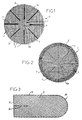
- Figure 1 shows a prosthetic implant shutter 1 according to the present invention, seen in plan of above.
- the prosthetic implant is generally shaped circular, and for example has a diameter of about 8 cm. This shape can of course vary, and we can use for example prosthetic implants of shape elliptical, for example having a diameter included between about 6.5 cm (small diameter), and 8.5 cm (large diameter).
- the obturator prosthetic implant 1 in its conformation not picked up flat, includes one element porous textile, shaped like a piece with an edge outside or around 5 continuous, and is constituted by a plate 2 (upper according to Fig. 1) and a second plate 3 (lower according to Fig. 1), superimposed and each composed of knitted warp and weft threads, relatively flexible prosthetic fabric, for example non-absorbable biocompatible polymer, and preferably base of multi-strand polyester thread 50 dtex.
- a fabric prosthetic is manufactured and marketed by the applicant under the reference PAC, and consists of a knitted fabric with woven chain, square days, made with three layers of chain son. The fabric has good stability bidirectional and cannot be cut when cut.
- the two plates can of course be of the same type or different but usually each have a two-dimensional grid structure, for example with pores of about 1.5 mm x 1.5 mm. As we can see it in figure 1, in relation to the grid of the two-dimensional structure, the two plates can be angularly offset from each other, and the plate 3 is preferably oriented at 45 ° by compared to plate 2.
- radiator elements and plication guide, extending and distributed around a central area 6 free from any said radiant element.
- the elements radials 4 determine, when applying a thrust local, for example with your finger, in the area central 6, and while constraining in a centripetal way the remaining periphery of the textile element 1a, a conformation picked up in volume comprising at least two opposite hollow lobes 32, formed by the two plates 2 and 3 between the radiator elements 4.
- these radiating elements 4 are integrated into the textile element, bracing the two plates, and binding them to each other.
- the plates are elliptical in shape
- the seams radials 4 have unequal lengths, and they converge towards the geometric center 6a of the ellipse, stopping by example about 1 cm from it. So the elements radiators 4 do not extend to the center geometric 6a of the textile element la, but up to the central zone 6, which avoids the risk of perforation or trauma to sensitive organs in or around the orifice or channel to be closed when the implant is in its conformation picked up.
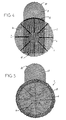
- the obturator prosthetic implant according to FIG. 2 differs from that shown in accordance with Figure 1, in that the textile element comprises it in addition a third plate 7, preferably with structure three-dimensional porous rehabitable, and presenting by example a thickness of about 1.5 to 2 mm.
- a third plate 7 preferably with structure three-dimensional porous rehabitable, and presenting by example a thickness of about 1.5 to 2 mm.
- This plate is marketed by the applicant, under the PAT name.
- This plate is a chain knit three-dimensional spacer, having two faces hexagonal days linked by a thread spacer of chain, and which gives it elasticity three-way.
- the third plate is the one that will rely on the various organs during the repair a direct inguinal hernia for example, and will protect these from possibly traumatic contact with the plates 2 and 3.
- the plates 2 and 3 are secured to the third plate 7 by discontinuous overcasting 8 along of the common circular edge 5 of said plates.
- the thread of overcasting is preferably identical to that used for the radiator elements 4.
- the assembly obtained in accordance with FIG. 2 can be optionally coated with collagen, for example bovine type 1.
- FIG. 3 illustrates a cover plate complementary for the prosthetic implant according to the invention.
- This plate 9 can have a width about 4.5 cm and a length of about 11 cm, and is generally rectangular in shape. It includes a slot 10, adapted to receive an anatomical conduit, by example the sperm vessels in case of repair hernial, and extending from a straight edge inside 11, or short side of plate 9, preferably perpendicular to the transverse edge 12, or long side of plate 9; the slot 10 extends in the middle of the plate, over a length of about 3 cm. Opposite the edge rounded exterior 11 of cover plate 9 complementary, the latter has another edge exterior 30.
- the additional cover plate 9 is fixed on the textile element 1a, for example by sutures 13, so that the longitudinal axis of symmetry of said plate coincides with a diameter of the textile element circular la, with the inner edge 11 included in the circle defined by said textile element, and the edge outside 30 outside said circle.
- the fixation is advantageously carried out along the circular edge of the textile element la.
- the function of this plate additional overlap is to protect areas peripherals of the hernial opening, potentially fragile, risk of recurrence.
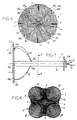
- the invention relates also a shutter assembly comprising an implant prosthetic obturator 1 as described above and a laying aid 14.
- This part of the invention is illustrated by Figures 6 to 9, in which the only difference compared to the prosthetic implant of the figures previous is that the 4 radiator and guide elements of plication, consist of only four seams distributed radially around the center geometrical 6a of the obturator implant, and extending over a shorter distance to the central area 6.
- a fitting aid 14 may consist of a rigid tubular element 15, for example a rigid cannula, in which a thread 16 has passed tensile, the wire 16 being freely interlaced in the plate 2 of the textile element 1, so that the ends of the wire 16, as well as a loop 17 formed of the wire 16 protrude from the open proximal end 15b of the tubular element 15.
- the wire 16 comes out of the element tubular 15 by openings 23a, 23b at a distance from the open distal end 15a of the tubular element 15, this distance corresponding for example at least to the distance between the geometric center 6a of the element textile from its outer edge 5, for example to at minus 4 cm (radius of the circle of the prosthetic implant shutter).
- the wire 16 passes from an opening 23a towards the outer edge 5 according to reference 16a, and around a warp or weft thread at a location 20a on the plate 2, to return according to reference 16b towards a diametrically opposite place 20b to that previously described, either by going back to the openings 23a and 23b, either directly according to reference 16c to return then towards the openings 23a, 23b according to the reference 16d.
- This operation is repeated with the same wire 16 according to references 16e, 16f, 16g and 16h, aux places 21a, 21b, so as to form a cross pattern; cf. figure 6.
- the prosthetic implant shutter 1 has a rosette shape, ready to introduction into the anatomical canal, orifice or cavity, by the surgeon.
- the installation instrument therefore allows with a single wire, for example looped, to pick up the obturator prosthetic implant 1 around the axis of the tubular element 15 by simple traction.
- the withdrawal of wire 16 is made by pulling the loop 17 and thus releases the implant in its site.
- This ancillary decreases the contact of the surgeon's fingers with the body, as well as with the implant, and allows to reach sites not accessible by finger alone.
- each hollow lobe 32 is delimited between a quarter-circle section of the first plate 2, of external convex shape, and a opposite section in quarter of the second plate 3, of concave interior shape, these sections being joined by two radiating elements 4, each common to two adjacent lobes 32.
- the four lobes 32 determine between them an internal cross shape.
- FIGs 10 and 11 show another mode preferred execution of the obturator prosthetic implant according to the invention. This other mode will be described only compared to the differences with the modes of execution of Figures 1 to 5.
- the obturator implant 24 has a shape semi-circular, in its shape not collected flat, and the textile element 1a is obtained by cutting a piece circular gathering three plates, interior 2, intermediate 3, and external 7 respectively. This piece is folded in two opposite sides according to a diameter d of the textile element la, so as to form a Semi circle.
- the three plates are connected by radiating elements 4, and the intermediate plates 3 and outer 7 connected to each other by overcasting.
- the inner plate 2 however, has at least two elements, for example seams 25,26 connecting its two opposite sides (see Figure 11).
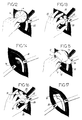
- the prosthetic implant shutter 1 When in use, the prosthetic implant shutter 1 is presented next to the channel or the orifice, for example inguinal, as shown schematically in Figures 12 to 17.
- the reference 35 indicates the spermatic cord.
- the implant is introduced into the orifice or channel by pressing on the area central 6 or the geometric center 6a of plate 2 of the textile element la using a finger, pliers or of the installation instrument.
- the implant passes, through the bias of a centripetal constraint on the remaining periphery of the textile element, which can be exercised for example through the walls of the inguinal opening, from the conformation to flat towards a conformation picked up in volume, such as illustrated by Figures 13, 14 and 16 in particular.
- a prosthetic implant according to the invention "molds" onto anatomical structures in relationship with the orifice or channel to be closed, and forms at minus two opposite hollow lobes 32, the elements radials 4 guiding plication and formation of lobes, and also giving the obturator implant a some radial resistance for better hold mechanical once implanted.
- Figures 15 to 17 show the application of the implant according to FIGS. 3 to 5, which does not differ from this which precedes that in that the complementary plate of cover 9 is positioned above the element textile there, so as to cover an anatomical area around the inguinal opening, to prevent possible recurrences, the slot 10 surrounding the vessels spermatic 35, as can be seen in FIG. 17.
Landscapes
- Health & Medical Sciences (AREA)
- Cardiology (AREA)
- Oral & Maxillofacial Surgery (AREA)
- Transplantation (AREA)
- Engineering & Computer Science (AREA)
- Biomedical Technology (AREA)
- Heart & Thoracic Surgery (AREA)
- Vascular Medicine (AREA)
- Life Sciences & Earth Sciences (AREA)
- Animal Behavior & Ethology (AREA)
- General Health & Medical Sciences (AREA)
- Public Health (AREA)
- Veterinary Medicine (AREA)
- Prostheses (AREA)
- Materials For Medical Uses (AREA)
Claims (12)
- Prothetisches Verschlußimplantat (1) zum Verschließen eines anatomischen Kanals, Hohlraums oder einer anatomischen Öffnung, mit einem porösen textilen Element (1a), das aus einem Prothesengewebe gefertigt ist, das in einem nicht gerafften flach ausgebreiteten Zustand die Form eines Stücks mit einem durchgehenden äußeren Rand oder Umfang (5) aufweist, wobei das Element zumindest zwei strahlenförmige Elemente (4) aufweist, die sich um einen mittigen Bereich (6), der von den strahlenförmigen Elementen frei ist, erstrecken und verteilt sind, und wobei die strahlenförmigen Elemente bei lokalem Druck in dem mittigen Bereich (6), wodurch der übrige Umfang des textilen Elements (1a) zentripetal eingezwängt wird, einen im Volumen gerafften Zustand bestimmen, dadurch gekennzeichnet, daß, in Kombination, einerseits das textile Element (1a), in den sich in Kontinuität sowohl der mittige Bereich als auch ein umliegender Bereich, der die strahlenförmigen Elemente aufweist, einbeschreibt, zumindest zwei übereinander angeordnete Lagen (2, 3) aus Prothesengewebe aufweist, und daß andererseits die beiden strahlenförmigen Elemente (4) die Form von zwei textilen Schnüren aufweisen, die jeweils durch eine Vielzahl von Stellen gebildet sind, die die beiden Lagen (2, 3) mit zumindest einem Faden verbinden.
- Implantat nach Anspruch 1, dadurch gekennzeichnet, daß im gerafften Zustand die beiden strahlenförmigen Elemente (4) zumindest zwei gegenüberliegende, offene oder geschlossene, hohle Lappen (32) bestimmen, die durch die beiden Lagen (2, 3) zwischen den strahlenförmigen Elementen (4) gebildet sind.
- Implantat nach Anspruch 1, dadurch gekennzeichnet, daß die strahlenförmigen Elemente (4) sich jeweils radial von dem äußeren Rand (5) des textilen Elements bis zu einer Zwischenstelle zwischen einem geometrischen Mittelpunkt (6a) des textilen Elements und dem äußeren Rand (5) des textilen Elements erstrecken.
- Implantat nach Anspruch 1, dadurch gekennzeichnet, daß die strahlenförmigen Elemente (4) sich jeweils radial bis zu dem mittigen Bereich (6) erstrecken.
- Implantat nach Anspruch 3, dadurch gekennzeichnet, daß die strahlenförmigen Elemente (4) sich jeweils von dem äußeren Rand (5) oder von diesem benachbart radial über eine begrenzte Länge erstrecken.
- Implantat nach Anspruch 1, dadurch gekennzeichnet, daß die beiden Lagen (2, 3) miteinander durch einen diskontinuierlichen Überkantstich (8) entlang der äußeren Ränder (5) der Lagen verbunden sind.
- Implantat nach Anspruch 1, dadurch gekennzeichnet, daß die strahlenförmigen Elemente (4) die Lagen (2, 3) durchdringen.
- Implantat nach Anspruch 1, dadurch gekennzeichnet, daß das textile Element (1a) zumindest drei untereinander verbundene Lagen (2, 3, 7) von identischer oder unterschiedlicher Beschaffenheit aufweist, wobei eine der Lagen gegebenenfalls eine dreidimensionale Struktur aufweist.
- Implantat nach Anspruch 8, dadurch gekennzeichnet, daß das textile Element (1a) in der Lage ist, durch Zuschnitt eines kreisförmigen Stücks erhalten zu werden, das durch Falten des Stückes um einen Durchmesser (d) zu zwei gegenüberliegenden Seiten eine äußere Lage (7), eine mittlere Lage (3) und eine innere Lage (2) zusammenfügt, wobei die strahlenförmigen Elemente (4) die drei Lagen untereinander verbinden, und zumindest zwei Elemente (25, 26) die beiden gegenüberliegenden Seiten der inneren Lage (2) verbinden.
- Implantat nach Anspruch 8, dadurch gekennzeichnet, daß die strahlenförmigen Elemente (4) zwei Lagen miteinander verbinden, wobei die dritte Lage (7) mit den beiden anderen (2, 3) durch den Überkantstich ihres äußeren Randes (5) verbunden ist.
- Implantat nach Anspruch 1, dadurch gekennzeichnet, daß es eine komplementäre Decklage (9) aufweist, die mit dem textilen Element (1a) verbunden ist, und die eine von letzterem unterschiedliche Form aufweist und mit einem geeigneten Schlitz zum Umgeben eines anatomischen Leiters versehen ist.
- Verschlußanordnung zum Verschließen eines anatomischen Kanals, Hohlraumes oder einer anatomischen Öffnung, mit einem Verschlußimplantat gemäß einem der Ansprüche 1 bis 11, und mit einer Anbringhilfe (14).
Applications Claiming Priority (3)
| Application Number | Priority Date | Filing Date | Title |
|---|---|---|---|
| FR9713464A FR2769825B1 (fr) | 1997-10-22 | 1997-10-22 | Implant prothetique obturateur de canal anatomique, et ensemble d'obturation le comportant |
| FR9713464 | 1997-10-22 | ||
| PCT/IB1998/001675 WO1999020204A1 (fr) | 1997-10-22 | 1998-10-21 | Implant prothetique obturateur de canal anatomique, et ensemble d'obturation le comportant |
Publications (2)
| Publication Number | Publication Date |
|---|---|
| EP1024764A1 EP1024764A1 (de) | 2000-08-09 |
| EP1024764B1 true EP1024764B1 (de) | 2001-08-22 |
Family
ID=9512705
Family Applications (1)
| Application Number | Title | Priority Date | Filing Date |
|---|---|---|---|
| EP98947707A Expired - Lifetime EP1024764B1 (de) | 1997-10-22 | 1998-10-21 | Prothesenimplantat zum verschliessen von körperkanälen sowie mit diesem implantat ausgestattete verschlusseinheit |
Country Status (9)
| Country | Link |
|---|---|
| US (1) | US6391060B1 (de) |
| EP (1) | EP1024764B1 (de) |
| JP (1) | JP4221149B2 (de) |
| AT (1) | ATE204445T1 (de) |
| AU (1) | AU9453998A (de) |
| DE (1) | DE69801447T2 (de) |
| ES (1) | ES2163297T3 (de) |
| FR (1) | FR2769825B1 (de) |
| WO (1) | WO1999020204A1 (de) |
Families Citing this family (113)
| Publication number | Priority date | Publication date | Assignee | Title |
|---|---|---|---|---|
| DE19942611C1 (de) * | 1999-08-31 | 2001-07-05 | Ethicon Gmbh | Verstärktes flächiges Implantat |
| US7052516B2 (en) | 1999-10-20 | 2006-05-30 | Anulex Technologies, Inc. | Spinal disc annulus reconstruction method and deformable spinal disc annulus stent |
| US8128698B2 (en) | 1999-10-20 | 2012-03-06 | Anulex Technologies, Inc. | Method and apparatus for the treatment of the intervertebral disc annulus |
| US8632590B2 (en) | 1999-10-20 | 2014-01-21 | Anulex Technologies, Inc. | Apparatus and methods for the treatment of the intervertebral disc |
| US7935147B2 (en) | 1999-10-20 | 2011-05-03 | Anulex Technologies, Inc. | Method and apparatus for enhanced delivery of treatment device to the intervertebral disc annulus |
| US6592625B2 (en) | 1999-10-20 | 2003-07-15 | Anulex Technologies, Inc. | Spinal disc annulus reconstruction method and spinal disc annulus stent |
| US7951201B2 (en) | 1999-10-20 | 2011-05-31 | Anulex Technologies, Inc. | Method and apparatus for the treatment of the intervertebral disc annulus |
| US7615076B2 (en) | 1999-10-20 | 2009-11-10 | Anulex Technologies, Inc. | Method and apparatus for the treatment of the intervertebral disc annulus |
| US7004970B2 (en) | 1999-10-20 | 2006-02-28 | Anulex Technologies, Inc. | Methods and devices for spinal disc annulus reconstruction and repair |
| US6425924B1 (en) * | 2000-03-31 | 2002-07-30 | Ethicon, Inc. | Hernia repair prosthesis |
| US6805695B2 (en) | 2000-04-04 | 2004-10-19 | Spinalabs, Llc | Devices and methods for annular repair of intervertebral discs |
| DE10019604C2 (de) * | 2000-04-20 | 2002-06-27 | Ethicon Gmbh | Implantat |
| FR2810536B1 (fr) | 2000-06-23 | 2002-09-27 | Cousin Biotech | Implant textile de reparation |
| US6610006B1 (en) * | 2000-07-25 | 2003-08-26 | C. R. Bard, Inc. | Implantable prosthesis |
| DE10041347A1 (de) * | 2000-08-23 | 2002-03-07 | Ethicon Gmbh | Flächiges Implantat |
| FR2818532B1 (fr) * | 2000-12-22 | 2003-05-30 | Cousin Biotech | Implant prothetique pour orifice anatomique ou chirurgical |
| CA2342641C (en) * | 2000-12-29 | 2009-03-03 | Ethicon, Inc. | Hernia repair prosthesis and method |
| US6653525B2 (en) | 2001-01-18 | 2003-11-25 | The Brigham And Women's Hospital, Inc. | Prosthetic device for respiratory patients |
| US6827743B2 (en) * | 2001-02-28 | 2004-12-07 | Sdgi Holdings, Inc. | Woven orthopedic implants |
| AU2002254157B2 (en) | 2001-03-09 | 2006-07-27 | Boston Scientific Limited | Medical slings |
| US8033983B2 (en) | 2001-03-09 | 2011-10-11 | Boston Scientific Scimed, Inc. | Medical implant |
| EP1365688B1 (de) | 2001-03-09 | 2011-02-16 | Boston Scientific Limited | System zum einsetzen einer schlinge |
| US6755868B2 (en) * | 2002-03-22 | 2004-06-29 | Ethicon, Inc. | Hernia repair device |
| AU2003259834A1 (en) | 2002-12-17 | 2004-07-29 | Boston Scientific Limited | Spacer for sling delivery system |
| GB0300784D0 (en) * | 2003-01-14 | 2003-02-12 | Barker Stephen G E | Inguinal hernia repair prosthesis |
| GB0300786D0 (en) * | 2003-01-14 | 2003-02-12 | Barker Stephen G E | Laparoscopic port hernia device |
| US8926637B2 (en) | 2003-06-13 | 2015-01-06 | Covidien Lp | Multiple member interconnect for surgical instrument and absorbable screw fastener |
| EP2298184A1 (de) | 2003-06-13 | 2011-03-23 | Tyco Healthcare Group LP | Verbindung aus mehreren Elementen für ein Operationsinstrument und resorbierbarer Schraubenbefestiger |
| US7361138B2 (en) | 2003-07-31 | 2008-04-22 | Scimed Life Systems, Inc. | Bioabsorbable casing for surgical sling assembly |
| FR2859624B1 (fr) * | 2003-09-16 | 2005-12-02 | Sofradim Production | Tricot prothetique a proprietes variables |
| CA2563347C (en) | 2004-04-20 | 2014-01-14 | Genzyme Corporation | Surgical mesh-like implant |
| US8298290B2 (en) | 2004-09-20 | 2012-10-30 | Davol, Inc. | Implantable prosthesis for soft tissue repair |
| KR100675379B1 (ko) * | 2005-01-25 | 2007-01-29 | 삼성전자주식회사 | 프린팅 시스템 및 프린팅 방법 |
| DE102005009356A1 (de) * | 2005-03-01 | 2006-09-07 | Ethicon Gmbh | Chirurgisches Implantat |
| US20060253203A1 (en) * | 2005-05-03 | 2006-11-09 | Alfredo Alvarado | Hernial prosthesis for intraprosthetic fixation |
| US7799079B2 (en) | 2006-01-18 | 2010-09-21 | Zimmer Spine, Inc. | Vertebral fusion device and method |
| EP3025653B1 (de) * | 2006-06-21 | 2021-06-16 | Cook Biotech Incorporated | Pfropfen zur behandlung gastrointestinaler fisteln |
| US7614258B2 (en) | 2006-10-19 | 2009-11-10 | C.R. Bard, Inc. | Prosthetic repair fabric |
| US20130190783A1 (en) * | 2007-03-15 | 2013-07-25 | Insighlra Medical, Inc. | Fibrotic band interrupter and implant introducing device |
| US20090024147A1 (en) * | 2007-07-18 | 2009-01-22 | Ralph James D | Implantable mesh for musculoskeletal trauma, orthopedic reconstruction and soft tissue repair |
| US20090187197A1 (en) * | 2007-08-03 | 2009-07-23 | Roeber Peter J | Knit PTFE Articles and Mesh |
| US20090036996A1 (en) * | 2007-08-03 | 2009-02-05 | Roeber Peter J | Knit PTFE Articles and Mesh |
| US8317808B2 (en) | 2008-02-18 | 2012-11-27 | Covidien Lp | Device and method for rolling and inserting a prosthetic patch into a body cavity |
| US9034002B2 (en) | 2008-02-18 | 2015-05-19 | Covidien Lp | Lock bar spring and clip for implant deployment device |
| US9398944B2 (en) | 2008-02-18 | 2016-07-26 | Covidien Lp | Lock bar spring and clip for implant deployment device |
| US9301826B2 (en) | 2008-02-18 | 2016-04-05 | Covidien Lp | Lock bar spring and clip for implant deployment device |
| US9833240B2 (en) | 2008-02-18 | 2017-12-05 | Covidien Lp | Lock bar spring and clip for implant deployment device |
| US8758373B2 (en) | 2008-02-18 | 2014-06-24 | Covidien Lp | Means and method for reversibly connecting a patch to a patch deployment device |
| US9393002B2 (en) | 2008-02-18 | 2016-07-19 | Covidien Lp | Clip for implant deployment device |
| US8808314B2 (en) | 2008-02-18 | 2014-08-19 | Covidien Lp | Device and method for deploying and attaching an implant to a biological tissue |
| US9393093B2 (en) | 2008-02-18 | 2016-07-19 | Covidien Lp | Clip for implant deployment device |
| WO2009104182A2 (en) | 2008-02-18 | 2009-08-27 | Polytouch Medical Ltd | A device and method for deploying and attaching a patch to a biological tissue |
| US9044235B2 (en) | 2008-02-18 | 2015-06-02 | Covidien Lp | Magnetic clip for implant deployment device |
| US9271706B2 (en) | 2008-08-12 | 2016-03-01 | Covidien Lp | Medical device for wound closure and method of use |
| US20100104608A1 (en) * | 2008-09-26 | 2010-04-29 | Tyco Healthcare Group Lp | Reactive surgical implant |
| US8241654B2 (en) * | 2008-09-26 | 2012-08-14 | Tyco Healthcare Group Lp | Reactive surgical implant |
| US8163022B2 (en) | 2008-10-14 | 2012-04-24 | Anulex Technologies, Inc. | Method and apparatus for the treatment of the intervertebral disc annulus |
| AU2009305958B9 (en) | 2008-10-20 | 2013-07-11 | Covidien Lp | A device for attaching a patch to a biological tissue |
| US20100111919A1 (en) | 2008-10-31 | 2010-05-06 | Tyco Healthcare Group Lp | Delayed gelation compositions and methods of use |
| DE102008044005A1 (de) * | 2008-11-24 | 2010-05-27 | Leibniz-Institut Für Polymerforschung Dresden E.V. | Flächiges Implantat und Verfahren zu seiner Herstellung |
| FR2945931B1 (fr) * | 2009-06-02 | 2012-07-27 | Jean Claude Sgro | Prothese destinee aux pathologies du type hernie ou eventration |
| US8460350B2 (en) * | 2009-06-19 | 2013-06-11 | Arthrex, Inc. | Graft protection mesh and fixation technique |
| US8906045B2 (en) | 2009-08-17 | 2014-12-09 | Covidien Lp | Articulating patch deployment device and method of use |
| US9999424B2 (en) | 2009-08-17 | 2018-06-19 | Covidien Lp | Means and method for reversibly connecting an implant to a deployment device |
| EP2475309A4 (de) | 2009-09-08 | 2015-07-29 | Atrium Medical Corp | Herniapflaster |
| US20110087274A1 (en) * | 2009-10-08 | 2011-04-14 | Tyco Healtcare Group LP, New Haven, Ct | Wound Closure Device |
| US9833225B2 (en) * | 2009-10-08 | 2017-12-05 | Covidien Lp | Wound closure device |
| US20110087273A1 (en) | 2009-10-08 | 2011-04-14 | Tyco Healthcare Group Lp | Wound Closure Device |
| US8617206B2 (en) * | 2009-10-08 | 2013-12-31 | Covidien Lp | Wound closure device |
| FR2951069B1 (fr) | 2009-10-09 | 2011-11-18 | Sofradim Production | Element de renfort d'un treillis |
| US8858592B2 (en) | 2009-11-24 | 2014-10-14 | Covidien Lp | Wound plugs |
| US8460319B2 (en) | 2010-01-11 | 2013-06-11 | Anulex Technologies, Inc. | Intervertebral disc annulus repair system and method |
| CA2802482C (en) | 2010-06-17 | 2017-06-06 | Washington University | Biomedical patches with aligned fibers |
| FR2968537B1 (fr) * | 2010-12-09 | 2013-04-19 | Sofradim Production | Prothese avec couture en zig-zag |
| FR2972626B1 (fr) | 2011-03-16 | 2014-04-11 | Sofradim Production | Prothese comprenant un tricot tridimensionnel et ajoure |
| US8968760B2 (en) | 2011-04-27 | 2015-03-03 | Covidien Lp | Attachment of a biomaterial to tissue |
| US9750839B2 (en) | 2011-06-30 | 2017-09-05 | Covidien Lp | Drug eluting medical devices |
| FR2977790B1 (fr) | 2011-07-13 | 2013-07-19 | Sofradim Production | Prothese pour hernie ombilicale |
| FR2977789B1 (fr) | 2011-07-13 | 2013-07-19 | Sofradim Production | Prothese pour hernie ombilicale |
| CA2849052C (en) | 2011-09-30 | 2019-11-05 | Sofradim Production | Reversible stiffening of light weight mesh |
| US20130156935A1 (en) | 2011-12-14 | 2013-06-20 | Rachit Ohri | Methods for Coating Medical Devices |
| FR2985170B1 (fr) | 2011-12-29 | 2014-01-24 | Sofradim Production | Prothese pour hernie inguinale |
| US9820837B2 (en) | 2012-04-10 | 2017-11-21 | Ethicon, Inc. | Single plane tissue repair patch |
| US9820839B2 (en) | 2012-04-10 | 2017-11-21 | Ethicon, Inc. | Single plane tissue repair patch having a locating structure |
| US9820838B2 (en) | 2012-04-10 | 2017-11-21 | Ethicon, Inc. | Single plane tissue repair patch |
| FR2992547B1 (fr) | 2012-06-29 | 2015-04-24 | Sofradim Production | Prothese pour hernie |
| FR2994185B1 (fr) | 2012-08-02 | 2015-07-31 | Sofradim Production | Procede de preparation d’une couche poreuse a base de chitosane |
| IN2015DN02299A (de) | 2012-09-21 | 2015-08-21 | Univ Washington | |
| FR2995788B1 (fr) | 2012-09-25 | 2014-09-26 | Sofradim Production | Patch hemostatique et procede de preparation |
| FR2995779B1 (fr) | 2012-09-25 | 2015-09-25 | Sofradim Production | Prothese comprenant un treillis et un moyen de consolidation |
| EP2943131B1 (de) * | 2013-01-09 | 2019-07-17 | Cook Medical Technologies LLC | Abdominalretraktor |
| AU2014209124A1 (en) | 2013-01-28 | 2015-09-17 | Cartiva, Inc. | Systems and methods for orthopedic repair |
| US9737294B2 (en) | 2013-01-28 | 2017-08-22 | Cartiva, Inc. | Method and system for orthopedic repair |
| US9572559B2 (en) | 2013-03-15 | 2017-02-21 | Covidien Lp | Port site closure |
| FR3004333B1 (fr) * | 2013-04-11 | 2019-08-23 | Biom'up | Prothese implantable de renfort, en particulier pour le renfort de la paroi abdominale |
| US9364311B2 (en) | 2013-12-13 | 2016-06-14 | Covidien Lp | Endoscopic system for winding and inserting a mesh |
| CA2940476C (en) | 2014-03-06 | 2019-05-07 | C.R. Bard, Inc. | Hernia repair patch |
| US10172700B2 (en) | 2014-12-01 | 2019-01-08 | C.R. Bard, Inc. | Prosthesis for repairing a hernia defect |
| EP3059255B1 (de) | 2015-02-17 | 2020-05-13 | Sofradim Production | Verfahren zur Herstellung einer Matrix auf Chitosanbasis mit faseroptischem Verstärkungselement |
| EP3085337B1 (de) | 2015-04-24 | 2022-09-14 | Sofradim Production | Prothese zur unterstützung einer bruststruktur |
| EP3106185B1 (de) | 2015-06-19 | 2018-04-25 | Sofradim Production | Synthetische prothese mit einem gewirk und einem nichtporösen film und verfahren zur formung davon |
| US10182899B2 (en) | 2015-12-28 | 2019-01-22 | C.R. Bard, Inc. | Prosthesis for repairing a hernia defect |
| EP3195830B1 (de) | 2016-01-25 | 2020-11-18 | Sofradim Production | Prothese zur hernienreparatur |
| US10632228B2 (en) | 2016-05-12 | 2020-04-28 | Acera Surgical, Inc. | Tissue substitute materials and methods for tissue repair |
| EP3312325B1 (de) | 2016-10-21 | 2021-09-22 | Sofradim Production | Verfahren zur herstellung eines netzes mit einem daran befestigten nahtmaterial mit widerhaken und dadurch erhaltenes netz |
| EP3398554B1 (de) | 2017-05-02 | 2025-06-25 | Sofradim Production | Prothese zur leistenbruch reparatur |
| US10624729B2 (en) | 2017-10-12 | 2020-04-21 | C.R. Bard, Inc. | Repair prosthetic curl mitigation |
| CN111012543A (zh) * | 2019-12-19 | 2020-04-17 | 江南大学 | 一种3d疝修补网及其制备方法 |
| US12064330B2 (en) | 2020-04-28 | 2024-08-20 | Covidien Lp | Implantable prothesis for minimally invasive hernia repair |
| CA3227437A1 (en) | 2021-07-29 | 2023-02-02 | Acera Surgical, Inc. | Particle-form hybrid-scale fiber matrix |
| US12201749B2 (en) | 2021-07-29 | 2025-01-21 | Acera Surgical, Inc. | Combined macro and micro-porous hybrid-scale fiber matrix |
| WO2023039381A1 (en) | 2021-09-07 | 2023-03-16 | Acera Surgical, Inc. | Materials and methods for nerve repair and regeneration |
| US12427008B2 (en) * | 2023-02-24 | 2025-09-30 | Michael Grant Svestka | Full coverage abdominal anatomic hernia mesh |
Family Cites Families (14)
| Publication number | Priority date | Publication date | Assignee | Title |
|---|---|---|---|---|
| US5141515A (en) * | 1990-10-11 | 1992-08-25 | Eberbach Mark A | Apparatus and methods for repairing hernias |
| US5361752A (en) * | 1991-05-29 | 1994-11-08 | Origin Medsystems, Inc. | Retraction apparatus and methods for endoscopic surgery |
| CA2082090C (en) * | 1991-11-05 | 2004-04-27 | Jack Fagan | Improved occluder for repair of cardiac and vascular defects |
| DK168419B1 (da) * | 1991-11-25 | 1994-03-28 | Cook Inc A Cook Group Company | Støtteindretning for bugvæg og apparat til indføring heraf |
| DE69201633T2 (de) * | 1991-11-25 | 1995-07-06 | Cook Inc | Vorrichtung zum Wiederherstellen einer Gewebeöffnung. |
| US5356432B1 (en) * | 1993-02-05 | 1997-02-04 | Bard Inc C R | Implantable mesh prosthesis and method for repairing muscle or tissue wall defects |
| US5368602A (en) * | 1993-02-11 | 1994-11-29 | De La Torre; Roger A. | Surgical mesh with semi-rigid border members |
| FR2720266B1 (fr) * | 1994-05-27 | 1996-12-20 | Cogent Sarl | Tissu prothétique. |
| US5916225A (en) * | 1994-09-29 | 1999-06-29 | Surgical Sense, Inc. | Hernia mesh patch |
| US5716409A (en) * | 1996-10-16 | 1998-02-10 | Debbas; Elie | Reinforcement sheet for use in surgical repair |
| US5922026A (en) * | 1997-05-01 | 1999-07-13 | Origin Medsystems, Inc. | Surgical method and prosthetic strip therefor |
| US5824082A (en) * | 1997-07-14 | 1998-10-20 | Brown; Roderick B. | Patch for endoscopic repair of hernias |
| US6066776A (en) * | 1997-07-16 | 2000-05-23 | Atrium Medical Corporation | Self-forming prosthesis for repair of soft tissue defects |
| US6241768B1 (en) * | 1997-08-27 | 2001-06-05 | Ethicon, Inc. | Prosthetic device for the repair of a hernia |
-
1997
- 1997-10-22 FR FR9713464A patent/FR2769825B1/fr not_active Expired - Fee Related
-
1998
- 1998-10-21 WO PCT/IB1998/001675 patent/WO1999020204A1/fr not_active Ceased
- 1998-10-21 ES ES98947707T patent/ES2163297T3/es not_active Expired - Lifetime
- 1998-10-21 DE DE69801447T patent/DE69801447T2/de not_active Expired - Lifetime
- 1998-10-21 AT AT98947707T patent/ATE204445T1/de not_active IP Right Cessation
- 1998-10-21 EP EP98947707A patent/EP1024764B1/de not_active Expired - Lifetime
- 1998-10-21 JP JP2000516615A patent/JP4221149B2/ja not_active Expired - Fee Related
- 1998-10-21 US US09/529,353 patent/US6391060B1/en not_active Expired - Lifetime
- 1998-10-21 AU AU94539/98A patent/AU9453998A/en not_active Abandoned
Also Published As
| Publication number | Publication date |
|---|---|
| EP1024764A1 (de) | 2000-08-09 |
| DE69801447D1 (de) | 2001-09-27 |
| FR2769825A1 (fr) | 1999-04-23 |
| DE69801447T2 (de) | 2001-12-06 |
| JP4221149B2 (ja) | 2009-02-12 |
| WO1999020204A1 (fr) | 1999-04-29 |
| ES2163297T3 (es) | 2002-01-16 |
| AU9453998A (en) | 1999-05-10 |
| JP2001520076A (ja) | 2001-10-30 |
| US6391060B1 (en) | 2002-05-21 |
| ATE204445T1 (de) | 2001-09-15 |
| FR2769825B1 (fr) | 1999-12-03 |
Similar Documents
| Publication | Publication Date | Title |
|---|---|---|
| EP1024764B1 (de) | Prothesenimplantat zum verschliessen von körperkanälen sowie mit diesem implantat ausgestattete verschlusseinheit | |
| EP1100401B1 (de) | Prothese zur chirurgischen behandlung der hernia | |
| EP1083842B1 (de) | Weichprothese, insbesondere zur heilung von hernia mittels laparoskopie | |
| FR2767671A1 (fr) | Dispositif obturateur prothetique pour l'obturation de canaux herniaires | |
| FR2829922A1 (fr) | Implant complet et universel pour la reparation des hernies par voie anterieure | |
| EP2334256B1 (de) | Operationsinstrument zur ablage einer prothese | |
| WO1996041588A1 (fr) | Prothese interne sous forme d'un support textile ou autre et son appareil d'insertion par voie coelioscopique | |
| FR2977789A1 (fr) | Prothese pour hernie ombilicale | |
| FR2767672A1 (fr) | Protheses pour l'obturation de canaux herniaires | |
| WO1999027869A1 (fr) | Dispositif pour la mise en place d'une prothese dans le traitement des hernies de l'aine par voie coelioscopique | |
| FR2951069A1 (fr) | Element de renfort d'un treillis | |
| FR2929835A1 (fr) | Attache chirurgicale pour la fixation d'une prothese herniaire | |
| FR2977790A1 (fr) | Prothese pour hernie ombilicale | |
| CA2909246A1 (fr) | Prothese implantable de renfort, en particulier pour le renfort de la paroi abdominale | |
| FR2778554A1 (fr) | Prothese textile implantable | |
| WO2004012572A2 (fr) | Dispositif d'occlusion d'une ouverture existant dans une paroi corporelle, implantable par voie mini-invasive, et ensemble de mise en place de ce dispositif | |
| EP1885279B1 (de) | System zur chirurgischen behandlung eines prolapsus und ein zur behandlung geeignetes implantat | |
| WO2001097713A1 (fr) | Implant textile de reparation | |
| EP1625831A1 (de) | Prothesenimplantat zum verschliessen. | |
| EP2379005B1 (de) | Implantierbare vorrichtung und prothesenimplantat mit mindestens einer solchen vorrichtung | |
| CA2667796A1 (fr) | Ecarteur laparoscopique | |
| EP2127614B1 (de) | Vorrichtung zur Verankerung und Leitung, Verfahren zur Herstellung einer derartigen Vorrichtung und Implantat mit einer derartigen Vorrichtung | |
| FR3121036A1 (fr) | Dispositif pour faciliter l’implantation d’un treillis chirurgical | |
| FR2948011A1 (fr) | Dispositif destine au traitement des hernies et en particulier des hernies ombilicales et eventrations sur trous de trocarts | |
| FR2929836A1 (fr) | Dispositif pour le positionnement, le maintien et la fixation peripherique d'une prothese |
Legal Events
| Date | Code | Title | Description |
|---|---|---|---|
| PUAI | Public reference made under article 153(3) epc to a published international application that has entered the european phase |
Free format text: ORIGINAL CODE: 0009012 |
|
| 17P | Request for examination filed |
Effective date: 20000411 |
|
| AK | Designated contracting states |
Kind code of ref document: A1 Designated state(s): AT BE CH CY DE DK ES FI FR GB GR IE IT LI LU MC NL PT SE |
|
| GRAG | Despatch of communication of intention to grant |
Free format text: ORIGINAL CODE: EPIDOS AGRA |
|
| 17Q | First examination report despatched |
Effective date: 20001208 |
|
| GRAG | Despatch of communication of intention to grant |
Free format text: ORIGINAL CODE: EPIDOS AGRA |
|
| GRAH | Despatch of communication of intention to grant a patent |
Free format text: ORIGINAL CODE: EPIDOS IGRA |
|
| GRAH | Despatch of communication of intention to grant a patent |
Free format text: ORIGINAL CODE: EPIDOS IGRA |
|
| GRAA | (expected) grant |
Free format text: ORIGINAL CODE: 0009210 |
|
| AK | Designated contracting states |
Kind code of ref document: B1 Designated state(s): AT BE CH CY DE DK ES FI FR GB GR IE IT LI LU MC NL PT SE |
|
| PG25 | Lapsed in a contracting state [announced via postgrant information from national office to epo] |
Ref country code: NL Free format text: LAPSE BECAUSE OF FAILURE TO SUBMIT A TRANSLATION OF THE DESCRIPTION OR TO PAY THE FEE WITHIN THE PRESCRIBED TIME-LIMIT Effective date: 20010822 Ref country code: FI Free format text: LAPSE BECAUSE OF FAILURE TO SUBMIT A TRANSLATION OF THE DESCRIPTION OR TO PAY THE FEE WITHIN THE PRESCRIBED TIME-LIMIT Effective date: 20010822 Ref country code: CY Free format text: LAPSE BECAUSE OF NON-PAYMENT OF DUE FEES Effective date: 20010822 Ref country code: AT Free format text: LAPSE BECAUSE OF FAILURE TO SUBMIT A TRANSLATION OF THE DESCRIPTION OR TO PAY THE FEE WITHIN THE PRESCRIBED TIME-LIMIT Effective date: 20010822 |
|
| REF | Corresponds to: |
Ref document number: 204445 Country of ref document: AT Date of ref document: 20010915 Kind code of ref document: T |
|
| REG | Reference to a national code |
Ref country code: CH Ref legal event code: EP |
|
| REF | Corresponds to: |
Ref document number: 69801447 Country of ref document: DE Date of ref document: 20010927 |
|
| REG | Reference to a national code |
Ref country code: IE Ref legal event code: FG4D Free format text: FRENCH |
|
| PG25 | Lapsed in a contracting state [announced via postgrant information from national office to epo] |
Ref country code: MC Free format text: LAPSE BECAUSE OF NON-PAYMENT OF DUE FEES Effective date: 20011021 Ref country code: LU Free format text: LAPSE BECAUSE OF NON-PAYMENT OF DUE FEES Effective date: 20011021 |
|
| PG25 | Lapsed in a contracting state [announced via postgrant information from national office to epo] |
Ref country code: SE Free format text: LAPSE BECAUSE OF FAILURE TO SUBMIT A TRANSLATION OF THE DESCRIPTION OR TO PAY THE FEE WITHIN THE PRESCRIBED TIME-LIMIT Effective date: 20011122 Ref country code: PT Free format text: LAPSE BECAUSE OF FAILURE TO SUBMIT A TRANSLATION OF THE DESCRIPTION OR TO PAY THE FEE WITHIN THE PRESCRIBED TIME-LIMIT Effective date: 20011122 Ref country code: DK Free format text: LAPSE BECAUSE OF FAILURE TO SUBMIT A TRANSLATION OF THE DESCRIPTION OR TO PAY THE FEE WITHIN THE PRESCRIBED TIME-LIMIT Effective date: 20011122 |
|
| REG | Reference to a national code |
Ref country code: CH Ref legal event code: NV Representative=s name: KIRKER & CIE SA |
|
| GBT | Gb: translation of ep patent filed (gb section 77(6)(a)/1977) |
Effective date: 20011117 |
|
| REG | Reference to a national code |
Ref country code: GB Ref legal event code: IF02 |
|
| REG | Reference to a national code |
Ref country code: ES Ref legal event code: FG2A Ref document number: 2163297 Country of ref document: ES Kind code of ref document: T3 |
|
| NLV1 | Nl: lapsed or annulled due to failure to fulfill the requirements of art. 29p and 29m of the patents act | ||
| REG | Reference to a national code |
Ref country code: GR Ref legal event code: EP Ref document number: 20010402199 Country of ref document: GR |
|
| PLBE | No opposition filed within time limit |
Free format text: ORIGINAL CODE: 0009261 |
|
| STAA | Information on the status of an ep patent application or granted ep patent |
Free format text: STATUS: NO OPPOSITION FILED WITHIN TIME LIMIT |
|
| 26N | No opposition filed | ||
| PGFP | Annual fee paid to national office [announced via postgrant information from national office to epo] |
Ref country code: IE Payment date: 20031007 Year of fee payment: 6 |
|
| PGFP | Annual fee paid to national office [announced via postgrant information from national office to epo] |
Ref country code: CH Payment date: 20040109 Year of fee payment: 6 |
|
| PG25 | Lapsed in a contracting state [announced via postgrant information from national office to epo] |
Ref country code: IE Free format text: LAPSE BECAUSE OF NON-PAYMENT OF DUE FEES Effective date: 20041021 |
|
| PG25 | Lapsed in a contracting state [announced via postgrant information from national office to epo] |
Ref country code: LI Free format text: LAPSE BECAUSE OF NON-PAYMENT OF DUE FEES Effective date: 20041031 Ref country code: CH Free format text: LAPSE BECAUSE OF NON-PAYMENT OF DUE FEES Effective date: 20041031 |
|
| REG | Reference to a national code |
Ref country code: CH Ref legal event code: PL |
|
| REG | Reference to a national code |
Ref country code: IE Ref legal event code: MM4A |
|
| PGFP | Annual fee paid to national office [announced via postgrant information from national office to epo] |
Ref country code: BE Payment date: 20071105 Year of fee payment: 10 |
|
| PGFP | Annual fee paid to national office [announced via postgrant information from national office to epo] |
Ref country code: GR Payment date: 20070928 Year of fee payment: 10 |
|
| BERE | Be: lapsed |
Owner name: *SOFRADIM PRODUCTION Effective date: 20081031 |
|
| PG25 | Lapsed in a contracting state [announced via postgrant information from national office to epo] |
Ref country code: BE Free format text: LAPSE BECAUSE OF NON-PAYMENT OF DUE FEES Effective date: 20081031 |
|
| PG25 | Lapsed in a contracting state [announced via postgrant information from national office to epo] |
Ref country code: GR Free format text: LAPSE BECAUSE OF NON-PAYMENT OF DUE FEES Effective date: 20090505 |
|
| REG | Reference to a national code |
Ref country code: FR Ref legal event code: PLFP Year of fee payment: 19 |
|
| PGFP | Annual fee paid to national office [announced via postgrant information from national office to epo] |
Ref country code: GB Payment date: 20160928 Year of fee payment: 19 |
|
| PGFP | Annual fee paid to national office [announced via postgrant information from national office to epo] |
Ref country code: FR Payment date: 20160921 Year of fee payment: 19 |
|
| PGFP | Annual fee paid to national office [announced via postgrant information from national office to epo] |
Ref country code: ES Payment date: 20160922 Year of fee payment: 19 |
|
| PGFP | Annual fee paid to national office [announced via postgrant information from national office to epo] |
Ref country code: DE Payment date: 20160922 Year of fee payment: 19 |
|
| PGFP | Annual fee paid to national office [announced via postgrant information from national office to epo] |
Ref country code: IT Payment date: 20160923 Year of fee payment: 19 |
|
| REG | Reference to a national code |
Ref country code: DE Ref legal event code: R119 Ref document number: 69801447 Country of ref document: DE |
|
| GBPC | Gb: european patent ceased through non-payment of renewal fee |
Effective date: 20171021 |
|
| REG | Reference to a national code |
Ref country code: FR Ref legal event code: ST Effective date: 20180629 |
|
| PG25 | Lapsed in a contracting state [announced via postgrant information from national office to epo] |
Ref country code: DE Free format text: LAPSE BECAUSE OF NON-PAYMENT OF DUE FEES Effective date: 20180501 Ref country code: GB Free format text: LAPSE BECAUSE OF NON-PAYMENT OF DUE FEES Effective date: 20171021 |
|
| PG25 | Lapsed in a contracting state [announced via postgrant information from national office to epo] |
Ref country code: FR Free format text: LAPSE BECAUSE OF NON-PAYMENT OF DUE FEES Effective date: 20171031 |
|
| PG25 | Lapsed in a contracting state [announced via postgrant information from national office to epo] |
Ref country code: IT Free format text: LAPSE BECAUSE OF NON-PAYMENT OF DUE FEES Effective date: 20171021 |
|
| REG | Reference to a national code |
Ref country code: ES Ref legal event code: FD2A Effective date: 20181221 |
|
| PG25 | Lapsed in a contracting state [announced via postgrant information from national office to epo] |
Ref country code: ES Free format text: LAPSE BECAUSE OF NON-PAYMENT OF DUE FEES Effective date: 20171022 |