EP1026108A2 - Verfahren zur Bildung von Kastenstapeln für Schnittgut - Google Patents
Verfahren zur Bildung von Kastenstapeln für Schnittgut Download PDFInfo
- Publication number
- EP1026108A2 EP1026108A2 EP00890025A EP00890025A EP1026108A2 EP 1026108 A2 EP1026108 A2 EP 1026108A2 EP 00890025 A EP00890025 A EP 00890025A EP 00890025 A EP00890025 A EP 00890025A EP 1026108 A2 EP1026108 A2 EP 1026108A2
- Authority
- EP
- European Patent Office
- Prior art keywords
- conveyor
- clippings
- conveying
- cross
- conveying direction
- Prior art date
- Legal status (The legal status is an assumption and is not a legal conclusion. Google has not performed a legal analysis and makes no representation as to the accuracy of the status listed.)
- Granted
Links
Images



Classifications
-
- B—PERFORMING OPERATIONS; TRANSPORTING
- B65—CONVEYING; PACKING; STORING; HANDLING THIN OR FILAMENTARY MATERIAL
- B65G—TRANSPORT OR STORAGE DEVICES, e.g. CONVEYORS FOR LOADING OR TIPPING, SHOP CONVEYOR SYSTEMS OR PNEUMATIC TUBE CONVEYORS
- B65G57/00—Stacking of articles
- B65G57/02—Stacking of articles by adding to the top of the stack
- B65G57/16—Stacking of articles of particular shape
- B65G57/18—Stacking of articles of particular shape elongated, e.g. sticks, rods, bars
-
- B—PERFORMING OPERATIONS; TRANSPORTING
- B65—CONVEYING; PACKING; STORING; HANDLING THIN OR FILAMENTARY MATERIAL
- B65G—TRANSPORT OR STORAGE DEVICES, e.g. CONVEYORS FOR LOADING OR TIPPING, SHOP CONVEYOR SYSTEMS OR PNEUMATIC TUBE CONVEYORS
- B65G47/00—Article or material-handling devices associated with conveyors; Methods employing such devices
- B65G47/22—Devices influencing the relative position or the attitude of articles during transit by conveyors
-
- B—PERFORMING OPERATIONS; TRANSPORTING
- B65—CONVEYING; PACKING; STORING; HANDLING THIN OR FILAMENTARY MATERIAL
- B65G—TRANSPORT OR STORAGE DEVICES, e.g. CONVEYORS FOR LOADING OR TIPPING, SHOP CONVEYOR SYSTEMS OR PNEUMATIC TUBE CONVEYORS
- B65G2201/00—Indexing codes relating to handling devices, e.g. conveyors, characterised by the type of product or load being conveyed or handled
- B65G2201/02—Articles
- B65G2201/0282—Wooden articles, e.g. logs, trunks or planks
Definitions
- the invention relates to a method for forming box stacks for Cuttings, preferably angular wooden boards, of different lengths, the Cuttings are collected by layers of accumulation and the front ends of the clippings alternately after a first and after a second stacking edge be aligned, whereby zigzag-like layers are formed, which by a Transfer device on a stacking table, preferably with the interposition of Spacer slats to be stacked.
- the individual layers are provided with the same dimensions by the boards are alternately aligned to the left and right stacking edges.
- At the delivery of the boards are initially based on an alignment edge, e.g. to the left, oriented. Every second board is left in this position, while the ones in between Boards are moved over a roller table until the right edge stops reached, which is spaced from the left edge in stack length.
- This type of stacking is mainly used in Scandinavia but also in Central Europe applied.
- planks are turned into an allocator a subsequent board conveyor with driver individually assigned, before each Carrier comes to lie a board.
- the drivers are included as short roles vertical axes.
- the chain of this cross conveyor is designed so that the Chain pieces between the drivers are of different heights, so that high and alternate low drivers and the height difference between a low and a high driver is for example 25 mm.
- the cross conveyor runs through an alignment roller conveyor with a length of about 2m Rollers, the roller drivers and the boards over the transverse roller conveyor be pushed. Due to the different height chain pieces of the cross conveyor leave every other board on the original alignment edge while the boards in between are aligned up to the stop by the roller table, which results in a so-called zigzag layer formation.
- the driver cross conveyor transfers the boards aligned in this way individually a subsequent layer formation cross conveyor. This runs every time the board is handed over a short step, which can be adjusted depending on the board width, and it forms one finished board layer.
- Transfer device also called transfer tongue
- Transfer tongue transfers the position to the stacking lifting table.
- the invention has for its object the performance of a Stacking system and thus to increase the number of stacks that can be produced per unit of time.
- this is achieved in that the clippings each due to the accumulation of cross-cut material piles immediately after the Congestion conveyor and collected during their conveying movement in finished layers and are transported, and that the zigzag-like alignment of the clippings during their further transport to the transfer device.
- the manipulation of the clippings can be done without a cross conveyor with a driver with smaller board distances, which results in a higher throughput Can achieve clippings.
- the transverse displacement movement taking place during the conveying movement with smaller board distances increases the performance of the invention Procedure.
- the transverse displacement takes place during the Conveying movement instead, but the boards have larger thanks to the cross conveyor with driver Distances.
- the invention relates to a system for forming box stacks a first and a second stacking edge for clippings, preferably wooden boards, with a jam cross conveyor, a stop device, an adjoining this Intermediate cross conveyor, a transfer device and a stacking table, in particular for Implementation of the method according to the invention.
- the object of the invention is the performance and thus the number of stack layers that can be generated per unit of time compared to known systems.
- the intermediate cross conveyor has a higher conveying speed than the accumulation cross conveyor that on one side of the Intermediate cross conveyor a device for transverse displacement every second Cut piece by a predetermined transverse displacement length is provided that - in Seen conveying direction - after the transverse displacement device a device for Prevention of a lateral displacement of the intermediate one along the first one Stacked-edge clippings are provided, which with a Alignment device for alignment of the shifted by the transverse displacement length Cuttings along the second stacking edge are in operative connection.
- a layer-forming device is which lowerable, adjustable stops in the conveying direction and one at a distance Layer width arranged clamping device.
- the intermediate cross conveyor is formed from a roof chain conveyor, and that to the side of the roof chain conveyor, a guide device, preferably an oblique one Angle to the direction of conveyance is arranged, the one Alignment of the piece goods along the first stacking edge, so that during the Conveying movement a very precise alignment can be achieved along the first stack edge can.
- the transverse displacement device from a parallel to Direction of conveyance of the system along a section slidable with transverse to Direction of conveyance aligned and displaceable sliding fingers is formed, which Carriage in the conveying direction with a conveying speed of the intermediate cross conveyor appropriate speed and against the conveying direction with a higher Rapid traverse speed is movable.
- the transverse displacement device can be made from a parallel to the Conveying direction rotatable drum with a screw-shaped one attached to it Insert cam be formed, the every second clippings transverse to the conveying direction moves and the circumference of the insertion cam with one of the Conveyor speed of the intermediate cross conveyor corresponding speed moves.
- the cam is dimensioned so that it extends over a circumferential angle extends from 180 °.
- the drum makes one revolution during the Intermediate conveyor (roof chain conveyor) covers the path of two board widths and shifts a board by approximately 100 mm during this rotation. Due to the shape of the snail the insertion cam remains the point of contact between the cam and the board during the Insertion process is the same, that is, the circumference of the screw and the intermediate conveyor run synchronously in the conveying direction. Due to the different board widths of the individual Box stack must pause after one revolution of the insertion drum until the beginning the next revolution can be of different sizes. Switching to another Working cycle takes place after passing the last boards of a stack before the start of the new one Assortment (distance 5.0 m).
- this device is to insert every other board by one predeterminable transverse displacement length, e.g. 100mm.
- the actual alignment process of the such shifted boards that can be aligned with the second stacking edge then be carried out particularly precisely if in a further embodiment of the invention it is provided that the alignment device from an angle to the conveying direction running alignment roller conveyor and a laterally, preferably obliquely, arranged stop conveyor belt is formed, the already shifted Cuttings are moved towards the second stacking edge, which by the Stop conveyor belt is defined.
- the transfer device has a, preferably multi-arm, layer transfer cross conveyor, one, preferably multi-armed, transfer tongue and a slide for Alignment of the longitudinal edge of the stack comprises, wherein the layer transfer cross conveyor is movable at the speed of the accumulation cross conveyor.
- the system according to the invention can be adjusted to a Shorter stack lengths can be achieved in that according to a further embodiment Invention is provided that the Einweis basicband, the transverse displacement device and the device for preventing the transverse displacement and the stop conveyor belt Parts of the alignment device each attached to a common sliding frame are.
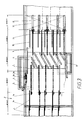
- Fig. 1 is a system for forming box stacks for clippings shown, whose main area of application is the stacking of angular sawn timber or Wooden boards of different lengths to form stacks of a uniform length.
- a stack length of 5.5 m with single board lengths of 2.4 m to 5.4 m be desired to stack these in drying chambers with given dimensions as efficient as possible and the applied dry heat as possible to take full advantage of.
- the system according to the invention can be used for everyone another type of cut or general cargo for the construction of stacks of the same length be used.
- the lumber on one Lumber sorting system according to the same thickness and the same width range sorted in different lengths.
- Every finished stack has - seen transversely to the longitudinal direction of the clippings - A first and a second stack edge.
- the clippings are fed via a accumulation conveyor 1 in the provided for a stack layer 30 number collected and the front ends of the Cuttings are alternately aligned with the first and second stacking edges, whereby zigzag-like layers are formed, which are transferred by a transfer device 9, 10, 11 can be stacked on a stacking table 12 with spacers placed between them.
- the system has, among other things, a layer-forming device 2 consisting of lowerable, adjustable in the conveying direction stops 2a and one in Distance of a layer width arranged clamping device 2b, one to this subsequent intermediate cross conveyor 3 and after the transfer device 10 one Stacking table 12, the function of which is described below.
- a layer-forming device 2 consisting of lowerable, adjustable in the conveying direction stops 2a and one in Distance of a layer width arranged clamping device 2b, one to this subsequent intermediate cross conveyor 3 and after the transfer device 10 one Stacking table 12, the function of which is described below.
- the intermediate cross conveyor 3 a higher conveying speed than the accumulation cross conveyor 1 and on one side of the Intermediate cross conveyor 3 a device for transverse displacement 5 every second, conveyed clippings by a predetermined transverse displacement length is provided. Furthermore - seen in the conveying direction - after the transverse displacement device 5 Device for preventing a transverse displacement 7 along the intermediate one of the first stack edge aligned clippings 25 provided with a Alignment device 6, 8 for aligning the shifted by the transverse displacement length Cuttings along the second stacking edge are in operative connection.
- the method according to the invention can be carried out on the system shown in FIG which are divided into a total of five sections for better understanding is. It differs from the known methods in that the Cross conveyor 1 accumulated clippings not broken down into individual pieces, then zigzag-like aligned and then combined again into layers, but it the clippings 25 each of the clippings stack layer pent up by the accumulation cross conveyor 30 immediately after the congestion cross promotion and during its conveying movement in Layer spacing arranged and the zigzag-like orientation of the Cuttings 25 take place during their further transport to the transfer device 9, 10, 11, from where the clippings 30 are transferred to a lifting table 12.
- the arrangement of the piece goods 25 in finished layers with small Spacing between the boards arises from the speed difference between the intermediate cross conveyor 3 and the accumulation cross conveyor 1, whereby the arrangement of the Cut pieces 25 is loosened accordingly.
- the transverse displacement device can also be by means of a other construction are carried out as a rotating drum 5a with a mounted on it screw-shaped insertion cam 5b, which over a Circumferential angle of 180 ° extends. With this device every second clippings 25 a passing layer 30 by at least 100 mm transverse to the conveying direction postponed.
- a Layer forming device 2 is provided, which in addition to, preferably lowerable, stops 2a has a clamping device 2b.
- the Clamping device activated, the stops 2a lowered and the finished layer on the Subsequent intermediate conveyor 3 in the part of the system designated as "2nd section" transferred, the intermediate cross conveyor preferably from a roof chain conveyor 3rd is formed.
- the clippings 25 are cut through a guide device, preferably from an oblique angle to the conveying direction employed injecting conveyor belt 4 is formed, exactly on the first board alignment edge instructed, which corresponds to the first stack edge, which is located in Fig.1, 2 above.
- the carriage 5 of Transverse sliding device begins with its displacement process.
- the width of the Cuttings are 4, 3 or 2 pieces of clippings at the same time with the help of the sliding fingers 21 by the predeterminable transverse displacement length, e.g. around 100mm, measured from the Board alignment edge or the first stack edge, shifted. But only every second one Cuttings 25 affected by the shift, while those in between Cut pieces 25 remain aligned along the first stacking edge.
- the Displacement process runs the carriage 5 of the transverse displacement device with the same Conveying speed as that of the intermediate cross conveyor 3 with and after completion of Pushing it in is quickly returned to the starting position.
- the distances between the displacement fingers 21 depend on the Clippings width and can be automatically correct every time the range is changed can be set.
- the displacement of the clippings 25 takes place in the embodiment 3 and 4 by means of an insertion cam 5b mounted on a drum 5a.
- the Alignment device from an alignment roller conveyor 6 that runs obliquely to the conveying direction and a stop conveyor belt 8 arranged laterally to this, preferably at an angle formed, the already shifted clippings 25 towards the second Stack edge are moved, which is defined by the stop conveyor 8.
- the respective cut layer 30 with the already 100mm each transversely displaced clippings 25 is from the roof chain conveyor 3 to the Transfer aligning roller conveyor 6, with both conveyors 3, 6 having the same conveying speed to have.
- Cuttings 25 are by a chain cross conveyor 7 during the Passed clamped and remain aligned along the first stack edge.
- the rest of the clippings that have already been moved forward are removed using the Aligning roller table 6 in the direction of the second stack edge until it is shifted come into contact with the stop conveyor belt 8 so that the desired zigzag-like Alignment exists without interruption of funding.
- the zigzag-like clippings 25 get into the "4th section" in which the transfer device is located, the one, preferably multi-arm, layer transfer cross conveyor 9, one, preferably multi-arm, Transfer tongue 10 and a slider 11 for aligning the longitudinal stack edge comprises, the layer transfer cross conveyor 9 at the speed of Jam conveyor 1 is movable, so that the clippings connect again.
- the multi-arm transfer tongue 10 starts and transfers this position to the stack lifting table 12.
- the transfer tongue 10 has a longitudinal axis swivel arms on the swung up edge with a non-slip Gearing are provided, and the respective clippings 30 above the level lift and only then a longitudinal extension movement towards the stacking lifting table 12 To run. In their extended end position, the arms swing back down and remain in this position for a moment, in which the slide 11 Cuttings layer 25 on your - seen in the conveying direction - back on a defined edge aligns. This process aligns the long edge of the stack.
- the "5th section” finally consists of the stacking lifting table 12 and one automatic batten laying device 13.
- the Transfer tongue 10 passes the slat laying device 13 with a distance slats Predeterminable distribution on the top of the cut material concerned.
- a multi-armed rake not shown, descends from above, its rake tines partly put on top of the clippings layer and partly in the gaps between drive the clippings and so hold this stack position.
- the Transfer tongue 10 back to its initial position, whereby the clippings layer together with the Spacer slats is placed on the lifting table 12 or on a stack that has already started.
- the stack lifting table 12 then lowers by the sum of the clippings thickness and Slat thickness off and a new transfer cycle can be carried out.
- the length of the stack or the clippings can be increased by a certain amount, e.g. 900 or shortened by 1000 mm.
- a certain amount e.g. 900 or shortened by 1000 mm.
- the stack length is 5500 mm maximum cut length of 5400 mm can with this change
- Stack length of 4600 mm with a maximum cut length of 4500 mm can be set. Such a change can be due to different Drying chamber dimensions may be required.
- the guide conveyor belt 4 are the Transverse displacement device 5 and the device for preventing Transverse displacement 7 attached to the sliding frame.
- the Transverse displacement device 5 Displacement of the aforementioned devices e.g. by 450 mm or 500 mm in the direction Be made in the middle of the plant.
- the stop conveyor 8 On the other side of the system is the stop conveyor 8 with parts of the Aligning roller conveyor 6 also built on a common sliding frame and this can also be shifted towards the center of the system by the aforementioned amount.
Landscapes
- Engineering & Computer Science (AREA)
- Mechanical Engineering (AREA)
- Attitude Control For Articles On Conveyors (AREA)
- Control And Other Processes For Unpacking Of Materials (AREA)
- Making Paper Articles (AREA)
- Debarking, Splitting, And Disintegration Of Timber (AREA)
- Stacking Of Articles And Auxiliary Devices (AREA)
- Cartons (AREA)
Abstract
Description
Claims (10)
- Verfahren zur Bildung von Kastenstapeln für Schnittgut, vorzugsweise kantige Holzbretter, mit unterschiedlicher Länge, wobei das Schnittgut durch Stauquerförderung zu Lagen gesammelt wird und die stirnseitigen Enden des Schnittguts abwechselnd nach einer ersten und nach einer zweiten Stapelkante ausgerichtet werden, wodurch zick-zack-artige Lagen gebildet werden, welche durch eine Übergabevorrichtung auf einem Stapeltisch, vorzugsweise unter Zwischenlage von Distanzlatten, gestapelt werden, dadurch gekennzeichnet, daß die Schnittgutstücke (25) jeder durch die Stauquerförderung aufgestauten Schnittgut-Stapellage (30) unmittelbar nach der Stauquerförderung und während ihrer Förderbewegung in fertigen Lagen gesammelt und transportiert werden, und daß die zick-zack-artige Ausrichtung der Schnittgutstücke (25) während ihres Weitertransportes zur Übergabevorrichtung erfolgt.
- Verfahren nach Anspruch 1, dadurch gekennzeichnet, daß zur zick-zack-artigen Ausrichtung der Schnittgutstücke (25) während eines Förderabschnitts jedes zweite Schnittgutstück (25) einer Lage (30) um eine vorbestimmte Querverschiebungslänge quer zur Förderrichtung verschoben wird, daß in einem darauffolgenden Förderabschnitt die dazwischenliegenden, nicht verschobenen Schnittgutstücke (25) gegen ein seitliches Verschieben gesichert werden, welche dadurch entlang der ersten Stapelkante ausgerichtet bleiben, daß die zuvor um eine vorbestimmbare Distanz verschobenen Schnittgutstücke (25) durch eine Ausrichtvorrichtung (6, 8) entlang der zweiten Stapelkante ausgerichtet werden, und daß die so ausgerichteten Stapellagen (30) der Übergabevorrichtung (9, 10, 11) zugeführt werden.
- Anlage zur Bildung von Kastenstapeln mit einer ersten und einer zweiten Stapelkante für Schnittgut, vorzugsweise, Holzbretter, mit einem Stauquerförderer, einer Anschlagvorrichtung, einem an diese anschließenden Zwischenquerförderer, einer Übergabevorrichtung und einem Stapeltisch, insbesondere nach einem der Ansprüche 1 oder 2, dadurch gekennzeichnet, daß der Zwischenquerförderer (3) eine höhere Fördergeschwindigkeit als der Stauquerförderer (1) aufweist, daß auf einer Seite des Zwischenquerförderers (3) eine Vorrichtung zur Querverschiebung (5) jedes zweiten Schnittgutstücks um eine vorbestimmte Querverschiebungslänge vorgesehen ist, daß - in Förderrichtung gesehen - nach der Querverschiebungsvorrichtung (5) eine Vorrichtung zur Verhinderung einer Querverschiebung (7) der dazwischenliegenden, entlang der ersten Stapelkante ausgerichteten Schnittgutteile (25) vorgesehen ist, welche mit einer Ausrichtvorrichtung (6, 8) zur Ausrichtung der um die Querverschiebungslänge verschobenen Schnittgutstücke entlang der zweiten Stapelkante in Wirkzusammenhang steht.
- Anlage nach Anspruch 3, dadurch gekennzeichnet, daß vor der Übergangsstelle zwischen dem, vorzugsweise mehrarmigen, Stauquerförderer (1) und dem Zwischenquerförderer (3) eine Lagenbildungsvorrichtung (2) vorgesehen ist, welche senkbare, in Förderrichtung verstellbare Anschläge und eine im Abstand einer Lagenbreite angeordnete Klemmvorrichtung aufweist.
- Anlage nach Anspruch 3 oder 4, dadurch gekennzeichnet, daß der Zwischenquerförderer aus einem Dachkettenförderer (3) gebildet ist, und daß seitlich des Dachkettenförderers (3) eine Einweisvorrichtung, vorzugsweise ein in schrägem Winkel zur Förderrichtung angestelltes Einweisförderband (4), angeordnet ist, die eine Ausrichtung der Stückgutteile (25) entlang der ersten Stapelkante vornimmt.
- Anlage nach einem der Ansprüche 3, 4 oder 5, dadurch gekennzeichnet, daß die Querverschiebungsvorrichtung aus einem parallel zur Förderrichtung der Anlage entlang eines Abschnitts verschiebbaren Schlitten (5) mit quer zur Förderrichtung ausgerichteten und verschiebbaren Verschiebefingern (21) gebildet ist, welcher Schlitten (5) in Förderrichtung mit einer der Fördergeschwindigkeit des Zwischenquerförderers (3) entsprechenden Geschwindigkeit und gegen die Förderrichtung mit einer höheren Eilganggeschwindigkeit bewegbar ist.
- Anlage nach einem der Ansprüche 3, 4 oder 5, dadurch gekennzeichnet, daß die Querverschiebevorrichtung aus einer parallel zur Förderrichtung rotierbaren Trommel (5a) mit einer darauf angebrachten, schneckenförmigen Einschiebenocke (5b) gebildet ist, die jedes zweite Schnittgutstück quer zur Förderrichtung verschiebt und wobei der Umfang der Einschiebnocke sich mit einer der Fördergeschwindigkeit des Zwischenquerförderers (3) entsprechenden Geschwindigkeit bewegt.
- Anlage nach einem der Ansprüche 3 bis 7, dadurch gekennzeichnet, daß die Ausrichtvorrichtung aus einem schräg zur Förderrichtung verlaufenden Ausrichtrollengang (6) und einem seitlich zu diesem, vorzugsweise schräg, angeordneten Anschlagförderband (8) gebildet ist, wobei die bereits verschobenen Schnittgutstücke (25) in Richtung zur zweiten Stapelkante verschoben werden, welche durch das Anschlagförderband (8) definiert ist.
- Anlage nach einem der Ansprüche 3 bis 8, dadurch gekennzeichnet, daß die Übergabevorrichtung einen, vorzugsweise mehrarmigen, Lagenübergabe-Querförderer (9), eine, vorzugsweise mehrarmige, Übergabezunge (10) und einen Schieber (11) zur Ausrichtung der längsseitigen Stapelkante umfaßt, wobei der Lagenübergabe-Querförderer (9) mit der Geschwindigkeit des Stauquerförderers (1) bewegbar ist.
- Anlage nach einem der vorhergehenden Ansprüche 3 bis 9, dadurch gekennzeichnet, daß das Einweisförderband (4), die Querverschiebungsvorrichtung (5) und die Vorrichtung zur Verhinderung der Querverschiebung (7) sowie das Anschlagförderband (8) mit Teilen der Ausrichtvorrichtung (6) jeweils auf einem gemeinsamen Verschieberahmen befestigt sind.
Priority Applications (2)
| Application Number | Priority Date | Filing Date | Title |
|---|---|---|---|
| DK00890025T DK1026108T3 (da) | 1999-02-02 | 2000-01-27 | Fremgangsmåde og anlæg til dannelse af kasseformede stabler til skæregods |
| AT00890025T ATE269831T1 (de) | 1999-02-02 | 2000-01-27 | Verfahren und anlage zur bildung von kastenstapeln für schnittgut |
Applications Claiming Priority (2)
| Application Number | Priority Date | Filing Date | Title |
|---|---|---|---|
| AT1300599 | 1999-02-02 | ||
| AT0013599A AT406766B (de) | 1999-02-02 | 1999-02-02 | Verfahren zur bildung von kastenstapeln für schnittgut |
Publications (3)
| Publication Number | Publication Date |
|---|---|
| EP1026108A2 true EP1026108A2 (de) | 2000-08-09 |
| EP1026108A3 EP1026108A3 (de) | 2001-05-30 |
| EP1026108B1 EP1026108B1 (de) | 2004-06-23 |
Family
ID=3482463
Family Applications (1)
| Application Number | Title | Priority Date | Filing Date |
|---|---|---|---|
| EP00890025A Expired - Lifetime EP1026108B1 (de) | 1999-02-02 | 2000-01-27 | Verfahren und Anlage zur Bildung von Kastenstapeln für Schnittgut |
Country Status (5)
| Country | Link |
|---|---|
| EP (1) | EP1026108B1 (de) |
| AT (2) | AT406766B (de) |
| DE (1) | DE50006859D1 (de) |
| DK (1) | DK1026108T3 (de) |
| ES (1) | ES2223445T3 (de) |
Cited By (4)
| Publication number | Priority date | Publication date | Assignee | Title |
|---|---|---|---|---|
| WO2013074019A1 (en) * | 2011-11-15 | 2013-05-23 | Renholmen Ab | Method and arrangement for forming stacks of timber |
| CN107310019A (zh) * | 2017-07-28 | 2017-11-03 | 淄博雅安建材有限公司 | 一种保温板齐边装置及齐边工艺 |
| CN116214640A (zh) * | 2023-03-10 | 2023-06-06 | 利洁士医疗器械(重庆)有限公司 | 一种具有定位结构的棉签机 |
| WO2024032861A1 (en) | 2022-08-11 | 2024-02-15 | System Tm A/S | A shaping plant and a method for shaping ends of elongated wood elements |
Family Cites Families (4)
| Publication number | Priority date | Publication date | Assignee | Title |
|---|---|---|---|---|
| DE1057974B (de) * | 1957-04-04 | 1959-05-21 | Kaukas Ab Oy | Vorrichtung zur schichtweisen Stapelung von gesaegtem Holz zum Zwecke der Trocknung |
| CH560151A5 (de) * | 1972-02-01 | 1975-03-27 | Balz Rudolf | |
| AU533055B2 (en) * | 1978-02-09 | 1983-10-27 | Commonwealth Scientific And Industrial Research Organisation | Vertical continuous feed timer kiln |
| US4663860A (en) * | 1984-02-21 | 1987-05-12 | Weyerhaeuser Company | Vertical progressive lumber dryer |
-
1999
- 1999-02-02 AT AT0013599A patent/AT406766B/de not_active IP Right Cessation
-
2000
- 2000-01-27 ES ES00890025T patent/ES2223445T3/es not_active Expired - Lifetime
- 2000-01-27 EP EP00890025A patent/EP1026108B1/de not_active Expired - Lifetime
- 2000-01-27 AT AT00890025T patent/ATE269831T1/de active
- 2000-01-27 DK DK00890025T patent/DK1026108T3/da active
- 2000-01-27 DE DE50006859T patent/DE50006859D1/de not_active Expired - Lifetime
Cited By (6)
| Publication number | Priority date | Publication date | Assignee | Title |
|---|---|---|---|---|
| WO2013074019A1 (en) * | 2011-11-15 | 2013-05-23 | Renholmen Ab | Method and arrangement for forming stacks of timber |
| EP2780265A4 (de) * | 2011-11-15 | 2015-07-29 | Renholmen Ab | Verfahren und anordnung zur bildung von holzstapeln |
| CN107310019A (zh) * | 2017-07-28 | 2017-11-03 | 淄博雅安建材有限公司 | 一种保温板齐边装置及齐边工艺 |
| CN107310019B (zh) * | 2017-07-28 | 2024-01-30 | 淄博雅安建材有限公司 | 一种保温板齐边装置及齐边工艺 |
| WO2024032861A1 (en) | 2022-08-11 | 2024-02-15 | System Tm A/S | A shaping plant and a method for shaping ends of elongated wood elements |
| CN116214640A (zh) * | 2023-03-10 | 2023-06-06 | 利洁士医疗器械(重庆)有限公司 | 一种具有定位结构的棉签机 |
Also Published As
| Publication number | Publication date |
|---|---|
| DE50006859D1 (de) | 2004-07-29 |
| EP1026108A3 (de) | 2001-05-30 |
| ATE269831T1 (de) | 2004-07-15 |
| DK1026108T3 (da) | 2004-11-01 |
| ES2223445T3 (es) | 2005-03-01 |
| AT406766B (de) | 2000-08-25 |
| ATA13599A (de) | 2000-01-15 |
| EP1026108B1 (de) | 2004-06-23 |
Similar Documents
| Publication | Publication Date | Title |
|---|---|---|
| EP0247408B1 (de) | Plattenaufteil- und -sortieranlage | |
| DE3110860C2 (de) | ||
| DE4404017C2 (de) | Verfahren und Vorrichtung zum Palettieren von Stückgütern | |
| DE2342445A1 (de) | Palettiervorrichtung | |
| DE3006229C2 (de) | Anlage zum Sortieren und Ablegen von Blätterstapeln | |
| DE3038058A1 (de) | Einrichtung zum aufstapeln von flachen gegenstaenden,insbesondere von faltschachtel-zuschnitten | |
| EP0472909B1 (de) | Vorrichtung zum Bilden von Reihen und Lagen von Flaschen | |
| EP1879817A1 (de) | Vorrichtung zum fördern und paketieren von holzquadern | |
| DE2928665A1 (de) | Verfahren und vorrichtung zum automatischen gruppieren von setzlagen eines stapelgutes | |
| EP0540505B1 (de) | Einrichtung zum Abstapeln von aus aufgeteilten, plattenförmigen Einzelwerkstücken oder Plattenpaketen hergestellten Einzelformaten | |
| DE69610636T2 (de) | Vorrichtung zum verpacken von mit dornen versehenen platten oder dergleichen | |
| EP1026108B1 (de) | Verfahren und Anlage zur Bildung von Kastenstapeln für Schnittgut | |
| DE4418359C2 (de) | Verfahren und Vorrichtung zum Ausrichten von Stückgut | |
| DE4209952C2 (de) | Einrichtung bei Buntaufteilanlagen | |
| DE2501012A1 (de) | Verfahren und vorrichtung zum aufeinandersetzen von stapeln | |
| EP4086012A1 (de) | Verfahren und anlage zum sortieren von lamellen | |
| DE3431819C2 (de) | ||
| DE2424223C3 (de) | Einrichtung zum Bereitstellen von | |
| DE3914320C2 (de) | Ablängvorrichtung | |
| DE1932692A1 (de) | Vorrichtung zum lagenweisen UEbereinanderstapeln von Walzprofilen | |
| DE3417097C2 (de) | ||
| DE10006482C2 (de) | Stapelgerät | |
| DE19712698C2 (de) | Anlage zum ausgerichteten Zuführen von Füllstreifen aus Dämmaterial im Zuge der Fertigung von Sandwichelementen | |
| DE3616921C2 (de) | ||
| CH555282A (de) | Einrichtung zum bilden von bretterlagen, die dazu bestimmt sind, zu einem stapel aufeinandergeschichtet zu werden. |
Legal Events
| Date | Code | Title | Description |
|---|---|---|---|
| PUAI | Public reference made under article 153(3) epc to a published international application that has entered the european phase |
Free format text: ORIGINAL CODE: 0009012 |
|
| AK | Designated contracting states |
Kind code of ref document: A2 Designated state(s): AT BE CH CY DE DK ES FI FR GB GR IE IT LI LU MC NL PT SE |
|
| AX | Request for extension of the european patent |
Free format text: AL;LT;LV;MK;RO;SI |
|
| PUAL | Search report despatched |
Free format text: ORIGINAL CODE: 0009013 |
|
| AK | Designated contracting states |
Kind code of ref document: A3 Designated state(s): AT BE CH CY DE DK ES FI FR GB GR IE IT LI LU MC NL PT SE |
|
| AX | Request for extension of the european patent |
Free format text: AL;LT;LV;MK;RO;SI |
|
| 17P | Request for examination filed |
Effective date: 20011120 |
|
| AKX | Designation fees paid |
Free format text: AT BE CH CY DE DK ES FI FR GB GR IE IT LI LU MC NL PT SE |
|
| AXX | Extension fees paid |
Free format text: LT PAYMENT 20011120;LV PAYMENT 20011120;SI PAYMENT 20011120 |
|
| 17Q | First examination report despatched |
Effective date: 20030116 |
|
| RTI1 | Title (correction) |
Free format text: METHOD AND MACHINE FOR STACKING WORKPIECES TO BE CUT |
|
| GRAP | Despatch of communication of intention to grant a patent |
Free format text: ORIGINAL CODE: EPIDOSNIGR1 |
|
| GRAS | Grant fee paid |
Free format text: ORIGINAL CODE: EPIDOSNIGR3 |
|
| RAP1 | Party data changed (applicant data changed or rights of an application transferred) |
Owner name: SPRINGER MASCHINENFABRIK AG |
|
| GRAA | (expected) grant |
Free format text: ORIGINAL CODE: 0009210 |
|
| AK | Designated contracting states |
Kind code of ref document: B1 Designated state(s): AT BE CH CY DE DK ES FI FR GB GR IE IT LI LU MC NL PT SE |
|
| AX | Request for extension of the european patent |
Extension state: LT LV SI |
|
| PG25 | Lapsed in a contracting state [announced via postgrant information from national office to epo] |
Ref country code: IE Free format text: LAPSE BECAUSE OF FAILURE TO SUBMIT A TRANSLATION OF THE DESCRIPTION OR TO PAY THE FEE WITHIN THE PRESCRIBED TIME-LIMIT Effective date: 20040623 Ref country code: NL Free format text: LAPSE BECAUSE OF FAILURE TO SUBMIT A TRANSLATION OF THE DESCRIPTION OR TO PAY THE FEE WITHIN THE PRESCRIBED TIME-LIMIT Effective date: 20040623 |
|
| REG | Reference to a national code |
Ref country code: GB Ref legal event code: FG4D Free format text: NOT ENGLISH |
|
| REG | Reference to a national code |
Ref country code: CH Ref legal event code: EP |
|
| REG | Reference to a national code |
Ref country code: IE Ref legal event code: FG4D Free format text: GERMAN |
|
| REF | Corresponds to: |
Ref document number: 50006859 Country of ref document: DE Date of ref document: 20040729 Kind code of ref document: P |
|
| REG | Reference to a national code |
Ref country code: SE Ref legal event code: TRGR |
|
| PG25 | Lapsed in a contracting state [announced via postgrant information from national office to epo] |
Ref country code: GR Free format text: LAPSE BECAUSE OF FAILURE TO SUBMIT A TRANSLATION OF THE DESCRIPTION OR TO PAY THE FEE WITHIN THE PRESCRIBED TIME-LIMIT Effective date: 20040923 |
|
| REG | Reference to a national code |
Ref country code: CH Ref legal event code: NV Representative=s name: TROESCH SCHEIDEGGER WERNER AG |
|
| REG | Reference to a national code |
Ref country code: DK Ref legal event code: T3 |
|
| NLV1 | Nl: lapsed or annulled due to failure to fulfill the requirements of art. 29p and 29m of the patents act | ||
| PG25 | Lapsed in a contracting state [announced via postgrant information from national office to epo] |
Ref country code: CY Free format text: LAPSE BECAUSE OF FAILURE TO SUBMIT A TRANSLATION OF THE DESCRIPTION OR TO PAY THE FEE WITHIN THE PRESCRIBED TIME-LIMIT Effective date: 20050127 Ref country code: LU Free format text: LAPSE BECAUSE OF NON-PAYMENT OF DUE FEES Effective date: 20050127 |
|
| PG25 | Lapsed in a contracting state [announced via postgrant information from national office to epo] |
Ref country code: MC Free format text: LAPSE BECAUSE OF NON-PAYMENT OF DUE FEES Effective date: 20050131 |
|
| REG | Reference to a national code |
Ref country code: ES Ref legal event code: FG2A Ref document number: 2223445 Country of ref document: ES Kind code of ref document: T3 |
|
| ET | Fr: translation filed | ||
| REG | Reference to a national code |
Ref country code: IE Ref legal event code: FD4D |
|
| PLBE | No opposition filed within time limit |
Free format text: ORIGINAL CODE: 0009261 |
|
| STAA | Information on the status of an ep patent application or granted ep patent |
Free format text: STATUS: NO OPPOSITION FILED WITHIN TIME LIMIT |
|
| 26N | No opposition filed |
Effective date: 20050324 |
|
| PG25 | Lapsed in a contracting state [announced via postgrant information from national office to epo] |
Ref country code: PT Free format text: LAPSE BECAUSE OF NON-PAYMENT OF DUE FEES Effective date: 20041123 |
|
| PGFP | Annual fee paid to national office [announced via postgrant information from national office to epo] |
Ref country code: CH Payment date: 20080124 Year of fee payment: 9 Ref country code: DK Payment date: 20080124 Year of fee payment: 9 Ref country code: ES Payment date: 20080125 Year of fee payment: 9 |
|
| PGFP | Annual fee paid to national office [announced via postgrant information from national office to epo] |
Ref country code: IT Payment date: 20080126 Year of fee payment: 9 |
|
| REG | Reference to a national code |
Ref country code: CH Ref legal event code: PL |
|
| REG | Reference to a national code |
Ref country code: DK Ref legal event code: EBP |
|
| PG25 | Lapsed in a contracting state [announced via postgrant information from national office to epo] |
Ref country code: LI Free format text: LAPSE BECAUSE OF NON-PAYMENT OF DUE FEES Effective date: 20090131 Ref country code: CH Free format text: LAPSE BECAUSE OF NON-PAYMENT OF DUE FEES Effective date: 20090131 |
|
| REG | Reference to a national code |
Ref country code: ES Ref legal event code: FD2A Effective date: 20090128 |
|
| PG25 | Lapsed in a contracting state [announced via postgrant information from national office to epo] |
Ref country code: ES Free format text: LAPSE BECAUSE OF NON-PAYMENT OF DUE FEES Effective date: 20090128 |
|
| PG25 | Lapsed in a contracting state [announced via postgrant information from national office to epo] |
Ref country code: DK Free format text: LAPSE BECAUSE OF NON-PAYMENT OF DUE FEES Effective date: 20090731 |
|
| PG25 | Lapsed in a contracting state [announced via postgrant information from national office to epo] |
Ref country code: IT Free format text: LAPSE BECAUSE OF NON-PAYMENT OF DUE FEES Effective date: 20090127 |
|
| REG | Reference to a national code |
Ref country code: FR Ref legal event code: PLFP Year of fee payment: 16 |
|
| REG | Reference to a national code |
Ref country code: FR Ref legal event code: PLFP Year of fee payment: 17 |
|
| REG | Reference to a national code |
Ref country code: FR Ref legal event code: PLFP Year of fee payment: 18 |
|
| REG | Reference to a national code |
Ref country code: AT Ref legal event code: HC Ref document number: 269831 Country of ref document: AT Kind code of ref document: T Owner name: SPRINGER MASCHINENFABRIK GMBH, AT Effective date: 20170508 |
|
| REG | Reference to a national code |
Ref country code: FR Ref legal event code: PLFP Year of fee payment: 19 |
|
| PGFP | Annual fee paid to national office [announced via postgrant information from national office to epo] |
Ref country code: GB Payment date: 20180125 Year of fee payment: 19 |
|
| PGFP | Annual fee paid to national office [announced via postgrant information from national office to epo] |
Ref country code: FR Payment date: 20180124 Year of fee payment: 19 Ref country code: BE Payment date: 20180124 Year of fee payment: 19 |
|
| PGFP | Annual fee paid to national office [announced via postgrant information from national office to epo] |
Ref country code: FI Payment date: 20190118 Year of fee payment: 20 Ref country code: DE Payment date: 20190124 Year of fee payment: 20 |
|
| PGFP | Annual fee paid to national office [announced via postgrant information from national office to epo] |
Ref country code: SE Payment date: 20190124 Year of fee payment: 20 Ref country code: AT Payment date: 20190110 Year of fee payment: 20 |
|
| REG | Reference to a national code |
Ref country code: LT Ref legal event code: MM9D Effective date: 20190127 |
|
| GBPC | Gb: european patent ceased through non-payment of renewal fee |
Effective date: 20190127 |
|
| REG | Reference to a national code |
Ref country code: BE Ref legal event code: MM Effective date: 20190131 |
|
| PG25 | Lapsed in a contracting state [announced via postgrant information from national office to epo] |
Ref country code: FR Free format text: LAPSE BECAUSE OF NON-PAYMENT OF DUE FEES Effective date: 20190131 |
|
| PG25 | Lapsed in a contracting state [announced via postgrant information from national office to epo] |
Ref country code: BE Free format text: LAPSE BECAUSE OF NON-PAYMENT OF DUE FEES Effective date: 20190131 |
|
| PG25 | Lapsed in a contracting state [announced via postgrant information from national office to epo] |
Ref country code: GB Free format text: LAPSE BECAUSE OF NON-PAYMENT OF DUE FEES Effective date: 20190127 |
|
| REG | Reference to a national code |
Ref country code: DE Ref legal event code: R071 Ref document number: 50006859 Country of ref document: DE |
|
| REG | Reference to a national code |
Ref country code: FI Ref legal event code: MAE |
|
| REG | Reference to a national code |
Ref country code: SE Ref legal event code: EUG |
|
| REG | Reference to a national code |
Ref country code: AT Ref legal event code: MK07 Ref document number: 269831 Country of ref document: AT Kind code of ref document: T Effective date: 20200127 |