EP1026336A2 - Interconnexion de fermes de toit - Google Patents
Interconnexion de fermes de toit Download PDFInfo
- Publication number
- EP1026336A2 EP1026336A2 EP00102016A EP00102016A EP1026336A2 EP 1026336 A2 EP1026336 A2 EP 1026336A2 EP 00102016 A EP00102016 A EP 00102016A EP 00102016 A EP00102016 A EP 00102016A EP 1026336 A2 EP1026336 A2 EP 1026336A2
- Authority
- EP
- European Patent Office
- Prior art keywords
- truss
- slot
- aperture
- pin
- relative movement
- Prior art date
- Legal status (The legal status is an assumption and is not a legal conclusion. Google has not performed a legal analysis and makes no representation as to the accuracy of the status listed.)
- Granted
Links
Images



Classifications
-
- E—FIXED CONSTRUCTIONS
- E04—BUILDING
- E04C—STRUCTURAL ELEMENTS; BUILDING MATERIALS
- E04C3/00—Structural elongated elements designed for load-supporting
- E04C3/02—Joists; Girders, trusses, or trusslike structures, e.g. prefabricated; Lintels; Transoms; Braces
- E04C3/04—Joists; Girders, trusses, or trusslike structures, e.g. prefabricated; Lintels; Transoms; Braces of metal
- E04C3/11—Joists; Girders, trusses, or trusslike structures, e.g. prefabricated; Lintels; Transoms; Braces of metal with non-parallel upper and lower edges, e.g. roof trusses
-
- E—FIXED CONSTRUCTIONS
- E04—BUILDING
- E04B—GENERAL BUILDING CONSTRUCTIONS; WALLS, e.g. PARTITIONS; ROOFS; FLOORS; CEILINGS; INSULATION OR OTHER PROTECTION OF BUILDINGS
- E04B7/00—Roofs; Roof construction with regard to insulation
- E04B7/02—Roofs; Roof construction with regard to insulation with plane sloping surfaces, e.g. saddle roofs
- E04B7/06—Constructions of roof intersections or hipped ends
-
- E—FIXED CONSTRUCTIONS
- E04—BUILDING
- E04B—GENERAL BUILDING CONSTRUCTIONS; WALLS, e.g. PARTITIONS; ROOFS; FLOORS; CEILINGS; INSULATION OR OTHER PROTECTION OF BUILDINGS
- E04B7/00—Roofs; Roof construction with regard to insulation
- E04B7/02—Roofs; Roof construction with regard to insulation with plane sloping surfaces, e.g. saddle roofs
- E04B7/06—Constructions of roof intersections or hipped ends
- E04B7/063—Hipped ends
-
- E—FIXED CONSTRUCTIONS
- E04—BUILDING
- E04C—STRUCTURAL ELEMENTS; BUILDING MATERIALS
- E04C3/00—Structural elongated elements designed for load-supporting
- E04C3/02—Joists; Girders, trusses, or trusslike structures, e.g. prefabricated; Lintels; Transoms; Braces
- E04C3/12—Joists; Girders, trusses, or trusslike structures, e.g. prefabricated; Lintels; Transoms; Braces of wood, e.g. with reinforcements, with tensioning members
- E04C3/17—Joists; Girders, trusses, or trusslike structures, e.g. prefabricated; Lintels; Transoms; Braces of wood, e.g. with reinforcements, with tensioning members with non-parallel upper and lower edges, e.g. roof trusses
-
- F—MECHANICAL ENGINEERING; LIGHTING; HEATING; WEAPONS; BLASTING
- F16—ENGINEERING ELEMENTS AND UNITS; GENERAL MEASURES FOR PRODUCING AND MAINTAINING EFFECTIVE FUNCTIONING OF MACHINES OR INSTALLATIONS; THERMAL INSULATION IN GENERAL
- F16B—DEVICES FOR FASTENING OR SECURING CONSTRUCTIONAL ELEMENTS OR MACHINE PARTS TOGETHER, e.g. NAILS, BOLTS, CIRCLIPS, CLAMPS, CLIPS OR WEDGES; JOINTS OR JOINTING
- F16B7/00—Connections of rods or tubes, e.g. of non-circular section, mutually, including resilient connections
- F16B7/04—Clamping or clipping connections
- F16B7/0433—Clamping or clipping connections for rods or tubes being in parallel relationship
-
- F—MECHANICAL ENGINEERING; LIGHTING; HEATING; WEAPONS; BLASTING
- F16—ENGINEERING ELEMENTS AND UNITS; GENERAL MEASURES FOR PRODUCING AND MAINTAINING EFFECTIVE FUNCTIONING OF MACHINES OR INSTALLATIONS; THERMAL INSULATION IN GENERAL
- F16B—DEVICES FOR FASTENING OR SECURING CONSTRUCTIONAL ELEMENTS OR MACHINE PARTS TOGETHER, e.g. NAILS, BOLTS, CIRCLIPS, CLAMPS, CLIPS OR WEDGES; JOINTS OR JOINTING
- F16B7/00—Connections of rods or tubes, e.g. of non-circular section, mutually, including resilient connections
- F16B7/22—Connections of rods or tubes, e.g. of non-circular section, mutually, including resilient connections using hooks or like elements
-
- E—FIXED CONSTRUCTIONS
- E04—BUILDING
- E04B—GENERAL BUILDING CONSTRUCTIONS; WALLS, e.g. PARTITIONS; ROOFS; FLOORS; CEILINGS; INSULATION OR OTHER PROTECTION OF BUILDINGS
- E04B1/00—Constructions in general; Structures which are not restricted either to walls, e.g. partitions, or floors or ceilings or roofs
- E04B1/18—Structures comprising elongated load-supporting parts, e.g. columns, girders, skeletons
- E04B1/24—Structures comprising elongated load-supporting parts, e.g. columns, girders, skeletons the supporting parts consisting of metal
- E04B1/2403—Connection details of the elongated load-supporting parts
- E04B2001/2409—Hooks, dovetails or other interlocking connections
- E04B2001/2412—Keyhole connections
-
- E—FIXED CONSTRUCTIONS
- E04—BUILDING
- E04C—STRUCTURAL ELEMENTS; BUILDING MATERIALS
- E04C3/00—Structural elongated elements designed for load-supporting
- E04C3/02—Joists; Girders, trusses, or trusslike structures, e.g. prefabricated; Lintels; Transoms; Braces
- E04C3/04—Joists; Girders, trusses, or trusslike structures, e.g. prefabricated; Lintels; Transoms; Braces of metal
- E04C2003/0486—Truss like structures composed of separate truss elements
-
- E—FIXED CONSTRUCTIONS
- E04—BUILDING
- E04C—STRUCTURAL ELEMENTS; BUILDING MATERIALS
- E04C3/00—Structural elongated elements designed for load-supporting
- E04C3/02—Joists; Girders, trusses, or trusslike structures, e.g. prefabricated; Lintels; Transoms; Braces
- E04C3/04—Joists; Girders, trusses, or trusslike structures, e.g. prefabricated; Lintels; Transoms; Braces of metal
- E04C2003/0486—Truss like structures composed of separate truss elements
- E04C2003/0491—Truss like structures composed of separate truss elements the truss elements being located in one single surface or in several parallel surfaces
-
- F—MECHANICAL ENGINEERING; LIGHTING; HEATING; WEAPONS; BLASTING
- F16—ENGINEERING ELEMENTS AND UNITS; GENERAL MEASURES FOR PRODUCING AND MAINTAINING EFFECTIVE FUNCTIONING OF MACHINES OR INSTALLATIONS; THERMAL INSULATION IN GENERAL
- F16B—DEVICES FOR FASTENING OR SECURING CONSTRUCTIONAL ELEMENTS OR MACHINE PARTS TOGETHER, e.g. NAILS, BOLTS, CIRCLIPS, CLAMPS, CLIPS OR WEDGES; JOINTS OR JOINTING
- F16B2200/00—Constructional details of connections not covered for in other groups of this subclass
- F16B2200/20—Connections with hook-like parts gripping behind a blind side of an element to be connected
-
- F—MECHANICAL ENGINEERING; LIGHTING; HEATING; WEAPONS; BLASTING
- F16—ENGINEERING ELEMENTS AND UNITS; GENERAL MEASURES FOR PRODUCING AND MAINTAINING EFFECTIVE FUNCTIONING OF MACHINES OR INSTALLATIONS; THERMAL INSULATION IN GENERAL
- F16B—DEVICES FOR FASTENING OR SECURING CONSTRUCTIONAL ELEMENTS OR MACHINE PARTS TOGETHER, e.g. NAILS, BOLTS, CIRCLIPS, CLAMPS, CLIPS OR WEDGES; JOINTS OR JOINTING
- F16B2200/00—Constructional details of connections not covered for in other groups of this subclass
- F16B2200/67—Rigid angle couplings
-
- Y—GENERAL TAGGING OF NEW TECHNOLOGICAL DEVELOPMENTS; GENERAL TAGGING OF CROSS-SECTIONAL TECHNOLOGIES SPANNING OVER SEVERAL SECTIONS OF THE IPC; TECHNICAL SUBJECTS COVERED BY FORMER USPC CROSS-REFERENCE ART COLLECTIONS [XRACs] AND DIGESTS
- Y10—TECHNICAL SUBJECTS COVERED BY FORMER USPC
- Y10T—TECHNICAL SUBJECTS COVERED BY FORMER US CLASSIFICATION
- Y10T403/00—Joints and connections
- Y10T403/32—Articulated members
- Y10T403/32114—Articulated members including static joint
- Y10T403/32131—One member is plate or side
- Y10T403/32155—Bearing component clamped to plate or side, e.g., bolted, etc.
-
- Y—GENERAL TAGGING OF NEW TECHNOLOGICAL DEVELOPMENTS; GENERAL TAGGING OF CROSS-SECTIONAL TECHNOLOGIES SPANNING OVER SEVERAL SECTIONS OF THE IPC; TECHNICAL SUBJECTS COVERED BY FORMER USPC CROSS-REFERENCE ART COLLECTIONS [XRACs] AND DIGESTS
- Y10—TECHNICAL SUBJECTS COVERED BY FORMER USPC
- Y10T—TECHNICAL SUBJECTS COVERED BY FORMER US CLASSIFICATION
- Y10T403/00—Joints and connections
- Y10T403/34—Branched
- Y10T403/341—Three or more radiating members
- Y10T403/344—Plural pairs of axially aligned members
-
- Y—GENERAL TAGGING OF NEW TECHNOLOGICAL DEVELOPMENTS; GENERAL TAGGING OF CROSS-SECTIONAL TECHNOLOGIES SPANNING OVER SEVERAL SECTIONS OF THE IPC; TECHNICAL SUBJECTS COVERED BY FORMER USPC CROSS-REFERENCE ART COLLECTIONS [XRACs] AND DIGESTS
- Y10—TECHNICAL SUBJECTS COVERED BY FORMER USPC
- Y10T—TECHNICAL SUBJECTS COVERED BY FORMER US CLASSIFICATION
- Y10T403/00—Joints and connections
- Y10T403/46—Rod end to transverse side of member
- Y10T403/4602—Corner joint
-
- Y—GENERAL TAGGING OF NEW TECHNOLOGICAL DEVELOPMENTS; GENERAL TAGGING OF CROSS-SECTIONAL TECHNOLOGIES SPANNING OVER SEVERAL SECTIONS OF THE IPC; TECHNICAL SUBJECTS COVERED BY FORMER USPC CROSS-REFERENCE ART COLLECTIONS [XRACs] AND DIGESTS
- Y10—TECHNICAL SUBJECTS COVERED BY FORMER USPC
- Y10T—TECHNICAL SUBJECTS COVERED BY FORMER US CLASSIFICATION
- Y10T403/00—Joints and connections
- Y10T403/57—Distinct end coupler
Definitions
- This invention relates to the inter-connection of roof trusses.
- Steel or timber roof trusses are typically fabricated in the factory, stacked flat for transport, and assembled together on site. Assembly usually involves bracing the first roof truss in position and thereafter adding further roof trusses until the roof framing is completed and self-supporting.
- a gable roof Whilst a gable roof, for example, generally does not involve any direct inter-connection of adjacent roof trusses, most styles of roof (eg. hipped roofs) involve direct inter-connection of adjacent roof trusses. This inter-connection of roof trusses is currently achieved utilising conventional fixing systems such as bolts, screws, nails or rivets.
- the present invention aims to provide a roof truss inter-connection system which requires less time, skill and attention on-site.
- a truss assembly including:-
- the present invention resides in a method of assembling roof trusses, the method including:-
- FIG 1 there is shown a perspective view of a typical hipped-end roof frame comprised of a number of different types of trusses.
- the roof frame is comprised of full trusses 2 (also known as girder" trusses or gable” trusses), an end truss 4, hip trusses 6 and jack trusses 8.
- Each full truss 2 is comprised of a pair of upper chords and a lower chord, with web members extending between the upper and lower chords in a bracing pattern as shown.
- a central upright web member 10 (sometimes known as a ,,king" web member) which extends from the apex of the upper chords downwardly to the mid point of the lower chord.
- Each half truss ie. end truss, hip truss or jack truss
- the inner end of each half truss is defined by an upright end web member 11 (best seen in FIGS 2 and 3) similar to the central upright web member 10 of the full truss.
- end truss 4 and two hip trusses 6 are joined to the mid point of the full truss 2.
- the connection occurs at this location between the central upright web member 10 of the full truss 2 and the upright end web members 11 of the end truss 4 and hip trusses 6, respectively.
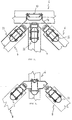
- FIG 2 there is shown an overhead view of the connection of the two hip trusses 6 and end truss 4 with the full truss 2. Also visible are the bottom chords of the four trusses. Perspective views of the same arrangement are shown in FIG 4.
- FIG 6 is an exploded perspective view of a connection assembly.
- a female three-way bracket 14 is connected to the central web member 10 of the full truss 2 via screws 18.
- the female bracket 14 includes three generally key-hole shaped apertures, each aperture comprised of an enlarged portion 26 which is generally circular in shape together with a slot portion 28 which extends downwardly away from the enlarged portion 26.
- a male bracket 12 is fixed to the end web member 11 of the end truss 4 via screws 16.
- the male bracket 12 includes a pin aperture 20 which is adapted to receive a pin 22. When the pin 22 is correctly seated within the pin aperture 20, a portion of the pin protrudes from the male bracket 12 as best shown in FIG 4B.
- the pin includes an enlarged head portion 32 and a neck portion 30 of lesser diameter than the head portion 32.
- the neck portion 30 extends from a shoulder portion 34 (see FIG 8 for more detail).
- the upperside of the head portion 32 of the pin 22 is chamfered to facilitate insertion into the enlarged portion 26 of the key-hole aperture in the female bracket 14 as will be appreciated from the following description of assembly.
- the underside of the head portion 32 of the pin 22 is chamfered to facilitate the entry of the neck portion 30 of the pin 22 into the slot portion 28 and to facilitate a close abutment of the female bracket 14 and male bracket 12.
- the male bracket 12 also includes a resilient locking tab 24.
- the resilient locking tab 24 has been formed such that the free distal end of the tab 24 normally stands proud of the surrounding planar surface of the male bracket 12.
- the free end of the tab 24 can be resiliently deflected so that it is substantially co-planar with the surrounding planar surface of the male bracket 12 but will resiliently return to its default position wherein it stands proud of the surrounding planar surface of the male bracket 12.
- connection assembly The operation of the connection assembly will now be described with reference to FIG 5.
- male bracket 12 is moved downwardly (in the slot direction) with respect to the female bracket 14 such that neck portion 30 of the pin is received within slot portion 28 of the key-hole aperture of the female bracket 14.
- the downward movement also causes the resilient locking tab 24 to initially become depressed and, as further downward movement occurs, the resilient locking tab 24 become aligned with enlarged portion 26 of the key-hole aperture of the female bracket 14 and the resilient nature of resilient locking tab 24 causes the resilient locking tab 24 to extend into and engage the enlarged portion 26 of the key-hole aperture of the female bracket 14 thereby preventing any reverse movement.
- connection assembly is provided at two vertically locations on each truss.
- the end truss or hip truss is connected to the full truss at the upper and lower ends of the central upright web member 10.
- male brackets 12 are fixed to the upper and lower ends of the upright web member 10 of the full truss.
- female brackets 14 are fixed to the upper and lower ends of the end or hip truss.
- each truss is connected to the adjacent truss at a pair of vertically spaced locations.
- the diameter of the neck portion 30 of the pin 22 is selected so as to be closely received in slot portion 28 of the key-hole aperture in the female bracket 14.
- the length of neck portion 30 of the pin 22 which is defined between shoulder portion 34 and head portion 28 is selected to correspond closely to the thickness of material forming the female bracket 14 (ie. the depth of the keyhole aperture) such that the planar material of the female bracket 14 surrounding the key-hole aperture is closely sandwiched between the planar male bracket 12 and head portion 32 of the pin 22.
- the chamfer on the underside of the head portion 32 of the pin 22 facilitates the reception of the planar material of the female bracket 14 between the head portion 32 and the planar male bracket 12.
- the length of slot portion 28 of the key-hole aperture is such that the resilient locking tab 24 extends and engages the enlarged portion 26 of the key-hole aperture concurrently with the neck portion 30 engaging the lower-most extent of the slot portion 28.
- the resilient locking tab 24 is complementary in shape to the enlarged portion 26.
- the free-end of resilient locking tab 24 is arcuate or semi-circular in shape such that it closely engages the upper half of the enlarged portion 26 of the key-hole aperture.
- each truss is connected to its neighbour at two vertically spaced locations.
- a three-way connection is which the end truss 4 and one hip truss 6 have already been connected to the full truss 2 and the remaining hip truss 6 is aligned and ready for connection.
- the remaining hip truss 6 will be converged with the full truss 2 such that the head 32 of the pin 22 is received through the enlarged portion 26 of the key-hole aperture in the female bracket 14.
- the remaining hip truss 6 will be displaced downwardly relative to the full truss 2 such that the neck portion 30 of the pin 22 traverses the length of the slot portion 28 of the key-hole aperture in the female bracket 14.
- the resilient locking tab 24 aligns with the enlarged portion 26 of the key-hole aperture and the free-end of the resilient locking tab 24 expands or extends into the enlarged portion of the key-hole aperture. It will be appreciated that reverse translation of the remaining hip truss 6 is thereafter prevented by the abutment of the free-end of the resilient locking tab 24 with the enlarged portion 26 of the key-hole aperture.
- FIG 3 there is shown the interconnection of the hip truss with a pair of jack trusses.
- the connection operation is identical to that previously described except that in this case the female bracket has two key-hole shaped apertures for a two-way connection of the hip truss 6 with the two jack trusses 8.
- the female bracket has two key-hole shaped apertures for a two-way connection of the hip truss 6 with the two jack trusses 8.
- other variants having less or more connection may be utilised.
- the present invention provides a connection system in which no tools are required and which is simple, quick and secure. As such it provides substantial on-site construction benefits when compared to alternative connection systems.
Landscapes
- Engineering & Computer Science (AREA)
- Architecture (AREA)
- Structural Engineering (AREA)
- General Engineering & Computer Science (AREA)
- Civil Engineering (AREA)
- Physics & Mathematics (AREA)
- Electromagnetism (AREA)
- Mechanical Engineering (AREA)
- Life Sciences & Earth Sciences (AREA)
- Wood Science & Technology (AREA)
- Joining Of Building Structures In Genera (AREA)
- Connector Housings Or Holding Contact Members (AREA)
- Connections Effected By Soldering, Adhesion, Or Permanent Deformation (AREA)
- Coupling Device And Connection With Printed Circuit (AREA)
Applications Claiming Priority (2)
| Application Number | Priority Date | Filing Date | Title |
|---|---|---|---|
| AUPP850499 | 1999-02-04 | ||
| AUPP8504A AUPP850499A0 (en) | 1999-02-04 | 1999-02-04 | Connection assembly |
Publications (3)
| Publication Number | Publication Date |
|---|---|
| EP1026336A2 true EP1026336A2 (fr) | 2000-08-09 |
| EP1026336A3 EP1026336A3 (fr) | 2001-05-09 |
| EP1026336B1 EP1026336B1 (fr) | 2005-04-20 |
Family
ID=3812704
Family Applications (1)
| Application Number | Title | Priority Date | Filing Date |
|---|---|---|---|
| EP00102016A Expired - Lifetime EP1026336B1 (fr) | 1999-02-04 | 2000-02-02 | Interconnexion de fermes de toit |
Country Status (5)
| Country | Link |
|---|---|
| US (1) | US6374566B1 (fr) |
| EP (1) | EP1026336B1 (fr) |
| AT (1) | ATE293727T1 (fr) |
| AU (1) | AUPP850499A0 (fr) |
| DE (1) | DE60019476D1 (fr) |
Cited By (4)
| Publication number | Priority date | Publication date | Assignee | Title |
|---|---|---|---|---|
| EP1398209A1 (fr) * | 2002-09-12 | 2004-03-17 | Valeo Vision | Agencement pour la fixation d'un dispositif d'éclairage ou de signalisation sur un support aménagé sur un véhicule automobile |
| WO2004079124A1 (fr) * | 2003-03-01 | 2004-09-16 | Ultraframe (Uk) Limited | Ameliorations apportees et relatives a des raccords d'empannon |
| DE102005036722B4 (de) * | 2005-07-28 | 2014-11-06 | Staiger Gmbh & Co. Kg | Haus |
| GB2543869B (en) * | 2015-10-28 | 2019-06-26 | Aanco Uk Ltd | Roof assembly and components thereof |
Families Citing this family (4)
| Publication number | Priority date | Publication date | Assignee | Title |
|---|---|---|---|---|
| US6772570B2 (en) * | 2000-10-18 | 2004-08-10 | Edward Horne | Variable pitch connector brackets for use in attaching supporting members to bearing members in roofs |
| US6758014B2 (en) * | 2002-10-15 | 2004-07-06 | Tai-Shan Chen | Trellis structure |
| US8365479B2 (en) * | 2011-06-17 | 2013-02-05 | Phat Energy Corporation | Solar power structure |
| EP4199698A4 (fr) * | 2019-12-30 | 2024-07-31 | Dövenci Çelik Konstürüksiyon Seracilik Demir Tarim Ürünleri Insaat Taahhüt Metal Ticaret ve Sanayi Limited Sirketi | Innovation apportée à la construction de serre |
Family Cites Families (10)
| Publication number | Priority date | Publication date | Assignee | Title |
|---|---|---|---|---|
| SE379087B (fr) * | 1973-07-27 | 1975-09-22 | A G Offenbroich | |
| US3849012A (en) * | 1973-10-24 | 1974-11-19 | T Krouse | Building structure fastener |
| FR2359302A1 (fr) * | 1976-07-21 | 1978-02-17 | Murphy Thomas | Elements structuraux d'interconnexion |
| DE2704398C3 (de) * | 1977-02-03 | 1980-08-21 | Plettac Gmbh, 5970 Plettenberg | Aus Ständern und Riegeln zusammensetzbares Gerüst |
| YU43416B (en) * | 1985-09-06 | 1989-06-30 | Vinko Martincic | Furniture angle clasp |
| US5114203A (en) | 1990-12-24 | 1992-05-19 | Chrysler Corporation | Retainer device and keyhole attaching arrangement |
| US5289665A (en) * | 1991-09-26 | 1994-03-01 | Higgins Gregory J | Orthogonal framework for modular building systems |
| JP2879392B2 (ja) * | 1992-04-17 | 1999-04-05 | カトウ産業株式会社 | 木造建築用軸組構造及び軸組具 |
| US5592789A (en) * | 1995-06-13 | 1997-01-14 | American Containment Systems, Inc. | Modular supporting structure |
| US5806265A (en) * | 1996-01-25 | 1998-09-15 | Sluiter; Scott E. | Metal truss joining gusset |
-
1999
- 1999-02-04 AU AUPP8504A patent/AUPP850499A0/en not_active Abandoned
-
2000
- 2000-02-02 AT AT00102016T patent/ATE293727T1/de not_active IP Right Cessation
- 2000-02-02 EP EP00102016A patent/EP1026336B1/fr not_active Expired - Lifetime
- 2000-02-02 DE DE60019476T patent/DE60019476D1/de not_active Expired - Lifetime
- 2000-02-04 US US09/497,882 patent/US6374566B1/en not_active Expired - Lifetime
Cited By (6)
| Publication number | Priority date | Publication date | Assignee | Title |
|---|---|---|---|---|
| EP1398209A1 (fr) * | 2002-09-12 | 2004-03-17 | Valeo Vision | Agencement pour la fixation d'un dispositif d'éclairage ou de signalisation sur un support aménagé sur un véhicule automobile |
| FR2844500A1 (fr) * | 2002-09-12 | 2004-03-19 | Valeo Vision | Agencement pour la fixation d'un dispositif d'eclairage ou de signalisation sur un support amenage sur un vehicule automobile |
| WO2004079124A1 (fr) * | 2003-03-01 | 2004-09-16 | Ultraframe (Uk) Limited | Ameliorations apportees et relatives a des raccords d'empannon |
| GB2399105B (en) * | 2003-03-01 | 2006-09-20 | Ultraframe Uk Ltd | Improvement in and relating to jack rafter connectors |
| DE102005036722B4 (de) * | 2005-07-28 | 2014-11-06 | Staiger Gmbh & Co. Kg | Haus |
| GB2543869B (en) * | 2015-10-28 | 2019-06-26 | Aanco Uk Ltd | Roof assembly and components thereof |
Also Published As
| Publication number | Publication date |
|---|---|
| US6374566B1 (en) | 2002-04-23 |
| EP1026336A3 (fr) | 2001-05-09 |
| EP1026336B1 (fr) | 2005-04-20 |
| AUPP850499A0 (en) | 1999-02-25 |
| ATE293727T1 (de) | 2005-05-15 |
| DE60019476D1 (de) | 2005-05-25 |
Similar Documents
| Publication | Publication Date | Title |
|---|---|---|
| US5335469A (en) | Rafter to plate connection | |
| US8443569B2 (en) | Four-way radial connector | |
| US4423977A (en) | Single element slope and skew hanger | |
| EP2527547B1 (fr) | Support de selle pour structure | |
| US4291996A (en) | Positive nail angling device for metal connectors | |
| US8931233B2 (en) | Building frame | |
| US6209268B1 (en) | Overhang support system for gable roofs | |
| US6877291B2 (en) | Strap holding device | |
| US20130247499A1 (en) | Compression Blocking Brace Bracket and Method of Use | |
| US4003179A (en) | Truss hanger | |
| US6427416B1 (en) | Connector plate | |
| AU2001245375A1 (en) | Truss brace and truss structure made therewith | |
| WO2001069000A1 (fr) | Contrevent d'entretoises et structure d'entretoises le comprenant | |
| US6374566B1 (en) | Inter-connection of roof trusses | |
| US6219975B1 (en) | Truss with integral hold down strap | |
| US6843028B2 (en) | Truss tie-down method and apparatus | |
| US4562683A (en) | Hinged metal webs for truss structures | |
| US6327823B1 (en) | Jointing device | |
| US4483120A (en) | Hinged metal web for truss structures and method of making | |
| AU765079B2 (en) | Inter-connection of roof trusses | |
| US6513298B2 (en) | Web connector | |
| EP0139599B1 (fr) | Moyen de support d'un pivot sur poutres, sous-poutres etc. | |
| AU773310B2 (en) | A portal frame | |
| JP3698059B2 (ja) | 切妻屋根の小屋組構造 | |
| AU767846B2 (en) | A truss tie-down method and apparatus |
Legal Events
| Date | Code | Title | Description |
|---|---|---|---|
| PUAI | Public reference made under article 153(3) epc to a published international application that has entered the european phase |
Free format text: ORIGINAL CODE: 0009012 |
|
| AK | Designated contracting states |
Kind code of ref document: A2 Designated state(s): AT BE CH CY DE DK ES FI FR GB GR IE IT LI LU MC NL PT SE |
|
| AX | Request for extension of the european patent |
Free format text: AL;LT;LV;MK;RO;SI |
|
| PUAL | Search report despatched |
Free format text: ORIGINAL CODE: 0009013 |
|
| AK | Designated contracting states |
Kind code of ref document: A3 Designated state(s): AT BE CH CY DE DK ES FI FR GB GR IE IT LI LU MC NL PT SE |
|
| AX | Request for extension of the european patent |
Free format text: AL;LT;LV;MK;RO;SI |
|
| 17P | Request for examination filed |
Effective date: 20010707 |
|
| AKX | Designation fees paid |
Free format text: AT BE CH CY DE DK ES FI FR GB GR IE IT LI LU MC NL PT SE |
|
| 17Q | First examination report despatched |
Effective date: 20031205 |
|
| GRAP | Despatch of communication of intention to grant a patent |
Free format text: ORIGINAL CODE: EPIDOSNIGR1 |
|
| GRAS | Grant fee paid |
Free format text: ORIGINAL CODE: EPIDOSNIGR3 |
|
| GRAA | (expected) grant |
Free format text: ORIGINAL CODE: 0009210 |
|
| AK | Designated contracting states |
Kind code of ref document: B1 Designated state(s): AT BE CH CY DE DK ES FI FR GB GR IE IT LI LU MC NL PT SE |
|
| PG25 | Lapsed in a contracting state [announced via postgrant information from national office to epo] |
Ref country code: AT Free format text: LAPSE BECAUSE OF FAILURE TO SUBMIT A TRANSLATION OF THE DESCRIPTION OR TO PAY THE FEE WITHIN THE PRESCRIBED TIME-LIMIT Effective date: 20050420 Ref country code: BE Free format text: LAPSE BECAUSE OF FAILURE TO SUBMIT A TRANSLATION OF THE DESCRIPTION OR TO PAY THE FEE WITHIN THE PRESCRIBED TIME-LIMIT Effective date: 20050420 Ref country code: FI Free format text: LAPSE BECAUSE OF FAILURE TO SUBMIT A TRANSLATION OF THE DESCRIPTION OR TO PAY THE FEE WITHIN THE PRESCRIBED TIME-LIMIT Effective date: 20050420 Ref country code: NL Free format text: LAPSE BECAUSE OF FAILURE TO SUBMIT A TRANSLATION OF THE DESCRIPTION OR TO PAY THE FEE WITHIN THE PRESCRIBED TIME-LIMIT Effective date: 20050420 Ref country code: LI Free format text: LAPSE BECAUSE OF FAILURE TO SUBMIT A TRANSLATION OF THE DESCRIPTION OR TO PAY THE FEE WITHIN THE PRESCRIBED TIME-LIMIT Effective date: 20050420 Ref country code: CH Free format text: LAPSE BECAUSE OF FAILURE TO SUBMIT A TRANSLATION OF THE DESCRIPTION OR TO PAY THE FEE WITHIN THE PRESCRIBED TIME-LIMIT Effective date: 20050420 Ref country code: IT Free format text: LAPSE BECAUSE OF FAILURE TO SUBMIT A TRANSLATION OF THE DESCRIPTION OR TO PAY THE FEE WITHIN THE PRESCRIBED TIME-LIMIT;WARNING: LAPSES OF ITALIAN PATENTS WITH EFFECTIVE DATE BEFORE 2007 MAY HAVE OCCURRED AT ANY TIME BEFORE 2007. THE CORRECT EFFECTIVE DATE MAY BE DIFFERENT FROM THE ONE RECORDED. Effective date: 20050420 |
|
| REG | Reference to a national code |
Ref country code: GB Ref legal event code: FG4D |
|
| REG | Reference to a national code |
Ref country code: CH Ref legal event code: EP |
|
| REG | Reference to a national code |
Ref country code: IE Ref legal event code: FG4D |
|
| REF | Corresponds to: |
Ref document number: 60019476 Country of ref document: DE Date of ref document: 20050525 Kind code of ref document: P |
|
| PG25 | Lapsed in a contracting state [announced via postgrant information from national office to epo] |
Ref country code: GR Free format text: LAPSE BECAUSE OF FAILURE TO SUBMIT A TRANSLATION OF THE DESCRIPTION OR TO PAY THE FEE WITHIN THE PRESCRIBED TIME-LIMIT Effective date: 20050720 Ref country code: DK Free format text: LAPSE BECAUSE OF FAILURE TO SUBMIT A TRANSLATION OF THE DESCRIPTION OR TO PAY THE FEE WITHIN THE PRESCRIBED TIME-LIMIT Effective date: 20050720 Ref country code: SE Free format text: LAPSE BECAUSE OF FAILURE TO SUBMIT A TRANSLATION OF THE DESCRIPTION OR TO PAY THE FEE WITHIN THE PRESCRIBED TIME-LIMIT Effective date: 20050720 |
|
| PG25 | Lapsed in a contracting state [announced via postgrant information from national office to epo] |
Ref country code: DE Free format text: LAPSE BECAUSE OF FAILURE TO SUBMIT A TRANSLATION OF THE DESCRIPTION OR TO PAY THE FEE WITHIN THE PRESCRIBED TIME-LIMIT Effective date: 20050721 |
|
| PG25 | Lapsed in a contracting state [announced via postgrant information from national office to epo] |
Ref country code: ES Free format text: LAPSE BECAUSE OF FAILURE TO SUBMIT A TRANSLATION OF THE DESCRIPTION OR TO PAY THE FEE WITHIN THE PRESCRIBED TIME-LIMIT Effective date: 20050731 |
|
| PG25 | Lapsed in a contracting state [announced via postgrant information from national office to epo] |
Ref country code: PT Free format text: LAPSE BECAUSE OF FAILURE TO SUBMIT A TRANSLATION OF THE DESCRIPTION OR TO PAY THE FEE WITHIN THE PRESCRIBED TIME-LIMIT Effective date: 20050920 |
|
| REG | Reference to a national code |
Ref country code: CH Ref legal event code: PL |
|
| NLV1 | Nl: lapsed or annulled due to failure to fulfill the requirements of art. 29p and 29m of the patents act | ||
| PG25 | Lapsed in a contracting state [announced via postgrant information from national office to epo] |
Ref country code: GB Free format text: LAPSE BECAUSE OF NON-PAYMENT OF DUE FEES Effective date: 20060202 Ref country code: IE Free format text: LAPSE BECAUSE OF NON-PAYMENT OF DUE FEES Effective date: 20060202 |
|
| PLBE | No opposition filed within time limit |
Free format text: ORIGINAL CODE: 0009261 |
|
| STAA | Information on the status of an ep patent application or granted ep patent |
Free format text: STATUS: NO OPPOSITION FILED WITHIN TIME LIMIT |
|
| PG25 | Lapsed in a contracting state [announced via postgrant information from national office to epo] |
Ref country code: LU Free format text: LAPSE BECAUSE OF NON-PAYMENT OF DUE FEES Effective date: 20060228 Ref country code: MC Free format text: LAPSE BECAUSE OF NON-PAYMENT OF DUE FEES Effective date: 20060228 |
|
| 26N | No opposition filed |
Effective date: 20060123 |
|
| EN | Fr: translation not filed | ||
| GBPC | Gb: european patent ceased through non-payment of renewal fee |
Effective date: 20060202 |
|
| REG | Reference to a national code |
Ref country code: IE Ref legal event code: MM4A |
|
| PG25 | Lapsed in a contracting state [announced via postgrant information from national office to epo] |
Ref country code: FR Free format text: LAPSE BECAUSE OF FAILURE TO SUBMIT A TRANSLATION OF THE DESCRIPTION OR TO PAY THE FEE WITHIN THE PRESCRIBED TIME-LIMIT Effective date: 20050420 Ref country code: CY Free format text: LAPSE BECAUSE OF FAILURE TO SUBMIT A TRANSLATION OF THE DESCRIPTION OR TO PAY THE FEE WITHIN THE PRESCRIBED TIME-LIMIT Effective date: 20050420 |