EP1026407A1 - Elément de commande fluidique - Google Patents
Elément de commande fluidique Download PDFInfo
- Publication number
- EP1026407A1 EP1026407A1 EP00101678A EP00101678A EP1026407A1 EP 1026407 A1 EP1026407 A1 EP 1026407A1 EP 00101678 A EP00101678 A EP 00101678A EP 00101678 A EP00101678 A EP 00101678A EP 1026407 A1 EP1026407 A1 EP 1026407A1
- Authority
- EP
- European Patent Office
- Prior art keywords
- housing
- control element
- sealing
- element according
- fluidic control
- Prior art date
- Legal status (The legal status is an assumption and is not a legal conclusion. Google has not performed a legal analysis and makes no representation as to the accuracy of the status listed.)
- Granted
Links
Images
Classifications
-
- F—MECHANICAL ENGINEERING; LIGHTING; HEATING; WEAPONS; BLASTING
- F16—ENGINEERING ELEMENTS AND UNITS; GENERAL MEASURES FOR PRODUCING AND MAINTAINING EFFECTIVE FUNCTIONING OF MACHINES OR INSTALLATIONS; THERMAL INSULATION IN GENERAL
- F16K—VALVES; TAPS; COCKS; ACTUATING-FLOATS; DEVICES FOR VENTING OR AERATING
- F16K11/00—Multiple-way valves, e.g. mixing valves; Pipe fittings incorporating such valves
- F16K11/02—Multiple-way valves, e.g. mixing valves; Pipe fittings incorporating such valves with all movable sealing faces moving as one unit
- F16K11/04—Multiple-way valves, e.g. mixing valves; Pipe fittings incorporating such valves with all movable sealing faces moving as one unit comprising only lift valves
- F16K11/052—Multiple-way valves, e.g. mixing valves; Pipe fittings incorporating such valves with all movable sealing faces moving as one unit comprising only lift valves with pivoted closure members, e.g. butterfly valves
-
- Y—GENERAL TAGGING OF NEW TECHNOLOGICAL DEVELOPMENTS; GENERAL TAGGING OF CROSS-SECTIONAL TECHNOLOGIES SPANNING OVER SEVERAL SECTIONS OF THE IPC; TECHNICAL SUBJECTS COVERED BY FORMER USPC CROSS-REFERENCE ART COLLECTIONS [XRACs] AND DIGESTS
- Y10—TECHNICAL SUBJECTS COVERED BY FORMER USPC
- Y10T—TECHNICAL SUBJECTS COVERED BY FORMER US CLASSIFICATION
- Y10T137/00—Fluid handling
- Y10T137/8593—Systems
- Y10T137/86493—Multi-way valve unit
- Y10T137/86847—Pivoted valve unit
-
- Y—GENERAL TAGGING OF NEW TECHNOLOGICAL DEVELOPMENTS; GENERAL TAGGING OF CROSS-SECTIONAL TECHNOLOGIES SPANNING OVER SEVERAL SECTIONS OF THE IPC; TECHNICAL SUBJECTS COVERED BY FORMER USPC CROSS-REFERENCE ART COLLECTIONS [XRACs] AND DIGESTS
- Y10—TECHNICAL SUBJECTS COVERED BY FORMER USPC
- Y10T—TECHNICAL SUBJECTS COVERED BY FORMER US CLASSIFICATION
- Y10T137/00—Fluid handling
- Y10T137/8593—Systems
- Y10T137/877—With flow control means for branched passages
- Y10T137/87708—With common valve operator
- Y10T137/87748—Pivoted or rotary motion converted to reciprocating valve head motion
Definitions
- the invention relates to a fluidic control element with a Housing and a control chamber formed in the housing in the at least two flow channels open. There is at least one in the control room Sealing seat arranged in which a flow channel enters. Furthermore located there is a sealing / actuating element surrounded by elastic material in the control room, that as a lever with two symmetrical arms is formed, which is pivotally mounted on the housing and in the simplest Case between a closed position, in which it ends with a Lever arm attached seat seal covers a sealing seat, as well as one Open position in which he releases the sealing seat, is movable.
- Fluidic control elements of the type mentioned at the outset are known from DE 295 07 380 U1.
- these known fluidic Control elements are the flow channels and the subsequent ones Valve seats diametrically in two approximately identical housing parts arranged.
- the control element is made up of a two-armed lever, which is stored in the middle of the housing. One of the lever arms will between the two opposite seats, the second Lever arm serves as a movement arm.
- the bearing element serves an elastic sleeve around the actuating element. Because of the diametrical arrangement of the valve seats, the channels in the fluidic control angled out to a simple maintain fluidic interface at all channels in one plane be led out of the fluidic control element. this leads to an undesirable increase in the internal volume and thus the remodeling housing.
- the invention has for its object a fluidic Control of the type mentioned in such a way that the fluidic interface without redirecting the channels horizontally one level is arranged in a housing part.
- the invention provides a fluidic control element provided, in which the sealing seats and the adjoining fluid channels are housed horizontally in one level in a housing part.
- the housing part serves as a cover.
- the two housing parts joined together along a parting plane and can be manufactured easily and inexpensively.
- housing parts is a combined sealing and Actuator clamped with an outer part, a rotatable Lever rests in the middle through a bearing arm on the housing and opens and closes, on its side facing the sealing seats attached seat seals, alternately the sealing seats left and right from this storage.
- the seal / actuator is complete surrounded by an envelope of elastic material, in which the Seat seals are integrated.
- the invention is characterized by the sealing / actuating element in the form of a two-armed lever with a right-angled to its longitudinal axis arranged bearing arm is provided, the outer ends, likewise closely enclosed by the covering, by means of this casing clamped between the two housing parts rotatable is stored.
- the type of storage is characterized by both large Compliance, so that only low driving forces are required as well as a precise definition of the swivel axis that uncontrolled movements of the two-armed lever despite its storage largely avoided in resilient material.
- the two-armed lever is actuated by introducing a Torque in the bearing arm, the ends of which from the fluid housing stick out.
- a Torque in the bearing arm
- Actuating arms that can be controlled in any way, e.g. by an electromagnet, a piezoelectric element, etc.
- the drive and required for the rotary movement of the lever Locking forces are in a further embodiment by a fluidic feedback significantly reduced.
- the fluidic Control is relieved of pressure in its holding positions that the upper part of the housing with the lever forms two pressure chambers through which Lever arms completely closed off from the work area and from each other are.
- the flow channels each assigned to a sealing seat communicate with one of the pressure rooms via feedback channels.
- the surface of the lever arm facing the respective pressure chamber becomes thus pressurized to the seat gasket this lever arm against the side facing away from the pressure chamber press the sealing seat located. Accordingly, the am Actuating arm drive forces to be applied.
- the fluidic control element according to the invention can be used to shut off Forwarding, throttling, switching, mixing or distributing Fluid flows are used.
- the one at the bottom of the case Opening flow channels preferably form a standardized fluidic interface to which other system elements with corresponding interfaces can be coupled.
- the bearing arm or the actuating arms are connected to different drive units coupled, which is also preferably standardized and therefore are interchangeable.
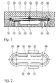
- Fig. 1 shows a preferred embodiment of the fluid Control in 3/2-way function with a generally flat, cuboid housing, which is composed of two housing parts 10, 11 is.
- a control chamber 12 is located between the housing parts 10, 11 educated.
- Two sealing seats 14, 14 ′ protrude into the control chamber 12 are formed in one plane on the housing part 10. From each sealing seat 14, 14 'starts a flow channel 16, 16' that runs straight and the Wall of the housing part 10 pierces.
- Another flow channel 15 leads from the control room 12 through the same wall and opens as the Flow channels 16, 16 'on the underside of the housing 10.
- Das Housing part 11 serves as a cover of the control room 12.
- a seal / actuator 13 In the Control room 12 is a seal / actuator 13, the from a solid core 19 surrounded by elastic material
- lever 23 which is pivotable between the housing parts 10, 11 is stored and is movable between two end positions, which Pivot bearing 22 of the lever 23 by a tightly enclosing it between two parts of the housing 10, 11 clamped sheath 18 elastic material is formed.
- the lever 23 covers one of the molded side of the lever arm 23a opposite the sealing seat 14 Seat seal 17 from the first sealing seat 14 and gives with the Sealing seat 14 'opposite side of the lever arm 23b by means of the molded seat seal 17 'the second sealing seat 14' free. In a second end position, the lever 23 opens the first sealing seat 14 and closes the second sealing seat 14 '.
- a combined sealing / actuating element 13 clamped which is shown separately in Fig. 2 is. It consists of a lever 23, the two control arms 23a, 23b forms a bearing arm 22, at the ends 22a, 22b of which Connect actuating arms 24 and a sealing frame 20 Elastomer material, which with the sheath 18 of the control arms 23a, 23b and of the bearing arm 22 forms a unit.
- This combined seal / actuator 13 is composed of a two-armed lever 23 together, the arms 23a, 23b form the control arms and the between these arms 23a, 23b perpendicular to the longitudinal axis of the two-armed lever 23 arranged bearing arm 22 is rotatably mounted.
- the outer ends of the Bearing arms 22 protrude from the sealing frame 20. To these ends the actuating approaches 21 follow.
- the sealing frame 20 surrounds the casing 18 of the control arms 23a, 23b at a distance and forms in installed condition an external limitation and sealing of the Control room 12.
- the bearing arm 22 is, as can be seen in FIG. 1, on the outer edge its casing 18 clamped between the housing parts 10, 11.
- the Envelope 18 made of elastomer material forms a pivot bearing for the ends of the bearing arm 22a, 22b and thus a pivot bearing for the from Control arms 23a, 23b existing two-armed lever 23.
- the sealing / actuating element 13 with its covering 18 is over the sealing seats 14, 14 'movable and covers with those formed on the casing 18 Seat seals 17, 17 'alternately release them.
- the sealing / actuating element 13 is driven by introduction of a torque in the bearing arm 22, the ends 22a, 22b of which Stick out, for example by moving the to the ends of the Bearing arms 22a, 22b subsequent actuating approaches 21.
Landscapes
- Engineering & Computer Science (AREA)
- General Engineering & Computer Science (AREA)
- Mechanical Engineering (AREA)
- Multiple-Way Valves (AREA)
- Servomotors (AREA)
- Lift Valve (AREA)
- Mechanically-Actuated Valves (AREA)
- Fluid-Driven Valves (AREA)
Applications Claiming Priority (2)
| Application Number | Priority Date | Filing Date | Title |
|---|---|---|---|
| DE29901855U | 1999-02-03 | ||
| DE29901855U DE29901855U1 (de) | 1999-02-03 | 1999-02-03 | Fluidisches Steuerelement |
Publications (2)
| Publication Number | Publication Date |
|---|---|
| EP1026407A1 true EP1026407A1 (fr) | 2000-08-09 |
| EP1026407B1 EP1026407B1 (fr) | 2004-11-17 |
Family
ID=8068872
Family Applications (1)
| Application Number | Title | Priority Date | Filing Date |
|---|---|---|---|
| EP00101678A Expired - Lifetime EP1026407B1 (fr) | 1999-02-03 | 2000-02-02 | Elément de commande fluidique |
Country Status (5)
| Country | Link |
|---|---|
| US (1) | US6394136B1 (fr) |
| EP (1) | EP1026407B1 (fr) |
| JP (1) | JP4585690B2 (fr) |
| DE (2) | DE29901855U1 (fr) |
| WO (1) | WO2000046515A1 (fr) |
Cited By (2)
| Publication number | Priority date | Publication date | Assignee | Title |
|---|---|---|---|---|
| US9115820B2 (en) | 2012-04-20 | 2015-08-25 | Buerkert Werke Gmbh | Fluidic control element with rounded shaft |
| EP2853792B2 (fr) † | 2013-09-26 | 2020-03-04 | Asco Numatics GmbH | Dispositif destiné à la régulation du débit d'un fluide |
Families Citing this family (28)
| Publication number | Priority date | Publication date | Assignee | Title |
|---|---|---|---|---|
| AT407661B (de) * | 1998-08-04 | 2001-05-25 | Hygrama Ag | Druckmittelzylinder, weichenventil und druckmittelbetätigte arbeitseinheit |
| EP1158182B1 (fr) | 2000-05-25 | 2004-12-08 | FESTO AG & Co | Agencement de soupape |
| DE10313484A1 (de) * | 2003-03-26 | 2004-10-07 | Zf Friedrichshafen Ag | Schaltventil mit kurzer Schaltzeit |
| US7070162B2 (en) * | 2003-07-18 | 2006-07-04 | South Bend Controls, Inc. | Valve actuating apparatus |
| US6962323B2 (en) * | 2003-07-22 | 2005-11-08 | Lockheed Martin Corporation | Apparatus comprising a rotary-acting pilot valve |
| US6974117B2 (en) * | 2003-08-27 | 2005-12-13 | South Bend Controls, Inc. | Proportional valve actuating apparatus |
| DE102006031567A1 (de) * | 2006-07-07 | 2008-01-10 | Siemens Ag | Einspritzsystem und Verfahren zum Herstellen eines Einspritzsystems |
| EP2068056B1 (fr) * | 2007-12-08 | 2010-08-04 | Asco Joucomatic GmbH | Dispositif destiné à la régulation du débit d'un milieu liquide ou gazeux |
| US8430378B2 (en) * | 2008-05-30 | 2013-04-30 | South Bend Controls Holdings Llc | High flow proportional valve |
| US20100314568A1 (en) * | 2009-06-15 | 2010-12-16 | South Bend Controls, Inc. | Solenoid coil |
| ITBS20100166A1 (it) * | 2010-10-13 | 2012-04-14 | Camozzi S P A Societa Unipersonal E | Valvola di controllo di un fluido |
| ITBS20100165A1 (it) * | 2010-10-13 | 2012-04-14 | Camozzi S P A Societa Unipersonal E | Valvola di controllo di un fluido |
| DE202011003472U1 (de) * | 2011-03-03 | 2011-05-05 | Bürkert Werke GmbH | Magnetventil |
| GB201115726D0 (en) * | 2011-09-12 | 2011-10-26 | Cambridge Entpr Ltd | Electromagnetic flexure |
| JP6228439B2 (ja) * | 2013-11-26 | 2017-11-08 | 住友ゴム工業株式会社 | 弁装置 |
| JP6228450B2 (ja) * | 2013-12-24 | 2017-11-08 | 住友ゴム工業株式会社 | 弁装置 |
| TWI652426B (zh) | 2014-11-19 | 2019-03-01 | 美商威士塔戴爾泰克有限責任公司 | 閥衝程放大機構總成 |
| DE102015219197B4 (de) * | 2015-10-05 | 2019-07-04 | Conti Temic Microelectronic Gmbh | Pneumatisches Magnetventil |
| US11248708B2 (en) | 2017-06-05 | 2022-02-15 | Illinois Tool Works Inc. | Control plate for a high conductance valve |
| US10364897B2 (en) | 2017-06-05 | 2019-07-30 | Vistadeltek, Llc | Control plate for a high conductance valve |
| US10323754B2 (en) | 2017-06-05 | 2019-06-18 | Vistadeltek, Llc | Control plate for a high conductive valve |
| US10458553B1 (en) | 2017-06-05 | 2019-10-29 | Vistadeltek, Llc | Control plate for a high conductive valve |
| EP3705764A1 (fr) * | 2019-03-05 | 2020-09-09 | Asco Numatics GmbH | Dispositif de régulation de débit d'un fluide |
| CN212455616U (zh) * | 2020-05-27 | 2021-02-02 | 北京科勒有限公司 | 切换阀 |
| CN215257991U (zh) | 2021-05-31 | 2021-12-21 | 南昌科勒有限公司 | 切换阀 |
| EP4098915B1 (fr) | 2021-05-31 | 2024-06-12 | Nanchang Kohler Ltd | Soupape de commutation |
| CN115507213B (zh) * | 2021-06-22 | 2025-05-06 | 科际精密股份有限公司 | 致动装置 |
| US11835144B2 (en) * | 2021-07-20 | 2023-12-05 | Smart Rs Inc. | Valve for bypass conduit |
Citations (4)
| Publication number | Priority date | Publication date | Assignee | Title |
|---|---|---|---|---|
| FR1249404A (fr) * | 1959-11-14 | 1960-12-30 | Rech Etudes Production Sarl | Vérin hydraulique autonome à alimentation électrique et à commande électrique |
| US4765370A (en) * | 1985-11-29 | 1988-08-23 | Fujikura Rubber Ltd. | Directional control valve |
| EP0488262A1 (fr) * | 1990-11-30 | 1992-06-03 | MATRIX S.r.l. | Clapet électromagnétique rapide à trois voies pour fluide sous pression par exemple, circuits pour gaz comprimés |
| DE29507380U1 (de) | 1995-05-03 | 1995-08-24 | Bürkert Werke GmbH & Co., 74653 Ingelfingen | Fluidisches Steuerelement |
Family Cites Families (4)
| Publication number | Priority date | Publication date | Assignee | Title |
|---|---|---|---|---|
| FR2609518B1 (fr) | 1987-01-12 | 1990-12-28 | Abx Sa | Microelectrovanne de commutation a une seule membrane |
| JPS63186078A (ja) * | 1987-01-28 | 1988-08-01 | Fujikura Rubber Ltd | 流路切換弁 |
| IE61313B1 (en) * | 1988-06-30 | 1994-10-19 | Abx Sa | Switching microelectrovalve having a single diaphragm |
| DE3940099A1 (de) | 1989-12-04 | 1991-06-06 | Wolf Woco & Co Franz J | Lamellenventil |
-
1999
- 1999-02-03 DE DE29901855U patent/DE29901855U1/de not_active Expired - Lifetime
-
2000
- 2000-02-02 US US09/623,525 patent/US6394136B1/en not_active Expired - Lifetime
- 2000-02-02 DE DE50008631T patent/DE50008631D1/de not_active Expired - Lifetime
- 2000-02-02 WO PCT/EP2000/000823 patent/WO2000046515A1/fr not_active Ceased
- 2000-02-02 EP EP00101678A patent/EP1026407B1/fr not_active Expired - Lifetime
- 2000-02-02 JP JP2000597561A patent/JP4585690B2/ja not_active Expired - Lifetime
Patent Citations (4)
| Publication number | Priority date | Publication date | Assignee | Title |
|---|---|---|---|---|
| FR1249404A (fr) * | 1959-11-14 | 1960-12-30 | Rech Etudes Production Sarl | Vérin hydraulique autonome à alimentation électrique et à commande électrique |
| US4765370A (en) * | 1985-11-29 | 1988-08-23 | Fujikura Rubber Ltd. | Directional control valve |
| EP0488262A1 (fr) * | 1990-11-30 | 1992-06-03 | MATRIX S.r.l. | Clapet électromagnétique rapide à trois voies pour fluide sous pression par exemple, circuits pour gaz comprimés |
| DE29507380U1 (de) | 1995-05-03 | 1995-08-24 | Bürkert Werke GmbH & Co., 74653 Ingelfingen | Fluidisches Steuerelement |
Cited By (2)
| Publication number | Priority date | Publication date | Assignee | Title |
|---|---|---|---|---|
| US9115820B2 (en) | 2012-04-20 | 2015-08-25 | Buerkert Werke Gmbh | Fluidic control element with rounded shaft |
| EP2853792B2 (fr) † | 2013-09-26 | 2020-03-04 | Asco Numatics GmbH | Dispositif destiné à la régulation du débit d'un fluide |
Also Published As
| Publication number | Publication date |
|---|---|
| WO2000046515A1 (fr) | 2000-08-10 |
| US6394136B1 (en) | 2002-05-28 |
| DE50008631D1 (de) | 2004-12-23 |
| JP4585690B2 (ja) | 2010-11-24 |
| WO2000046515A9 (fr) | 2001-10-11 |
| JP2002536600A (ja) | 2002-10-29 |
| DE29901855U1 (de) | 1999-04-08 |
| EP1026407B1 (fr) | 2004-11-17 |
Similar Documents
| Publication | Publication Date | Title |
|---|---|---|
| EP1026407B1 (fr) | Elément de commande fluidique | |
| EP1158182B1 (fr) | Agencement de soupape | |
| DE60129285T2 (de) | Elektromagnetisches Sitzventil | |
| EP1564464B1 (fr) | Soupape piézo-électrique | |
| EP1207329A1 (fr) | Soupape piezoélectrique | |
| EP0741248A2 (fr) | Elément de commande fluidique | |
| DE3346290A1 (de) | Magnetventil | |
| DE69715555T2 (de) | Druckregelventil montierbar an einem auf einer Grundplatte angebauten Umschaltventil | |
| DE10046141C2 (de) | Pneumatische Wegeventilanordnung | |
| DE2744917A1 (de) | Sitzventil mit geradem durchgang | |
| EP1899634B1 (fr) | Dispositif a soupape | |
| DE69817193T2 (de) | Membranventil und gehäuse eines membranventils | |
| AT393008B (de) | Fluidventil | |
| EP1477715B1 (fr) | Soupape à armature pivotante | |
| EP0145859B1 (fr) | Dispositif de soupape avec organe de commande piézo-électrique ou magnéto-strictif | |
| EP1281001A1 (fr) | Ensemble soupape pourvu d'un conduit d'ecoulement interne ayant un segment de longueur ouvert | |
| DE69811174T2 (de) | Vorgesteuertes Lenkungsregelventil | |
| WO2008141690A2 (fr) | Pompe | |
| DE2443687A1 (de) | Magnetventil | |
| EP0822360B1 (fr) | Soupape de commutation pour utilisation dans un combinaison de soupapes | |
| DE102009010312B3 (de) | Biegewandlerventil | |
| DE3031384C2 (de) | Einhebel-Mischventil | |
| DE7834499U1 (de) | Servobetaetigtes dreiwegeventil | |
| DE202006006862U1 (de) | Ventilvorrichtung | |
| DE4323893C1 (de) | Filterkopf |
Legal Events
| Date | Code | Title | Description |
|---|---|---|---|
| PUAI | Public reference made under article 153(3) epc to a published international application that has entered the european phase |
Free format text: ORIGINAL CODE: 0009012 |
|
| AK | Designated contracting states |
Kind code of ref document: A1 Designated state(s): DE FR GB |
|
| AX | Request for extension of the european patent |
Free format text: AL;LT;LV;MK;RO;SI |
|
| GBC | Gb: translation of claims filed (gb section 78(7)/1977) | ||
| 17P | Request for examination filed |
Effective date: 20000823 |
|
| EL | Fr: translation of claims filed | ||
| AKX | Designation fees paid |
Free format text: DE FR GB |
|
| 17Q | First examination report despatched |
Effective date: 20030310 |
|
| GRAP | Despatch of communication of intention to grant a patent |
Free format text: ORIGINAL CODE: EPIDOSNIGR1 |
|
| GRAA | (expected) grant |
Free format text: ORIGINAL CODE: 0009210 |
|
| GRAS | Grant fee paid |
Free format text: ORIGINAL CODE: EPIDOSNIGR3 |
|
| AK | Designated contracting states |
Kind code of ref document: B1 Designated state(s): DE FR GB |
|
| REG | Reference to a national code |
Ref country code: GB Ref legal event code: FG4D Free format text: NOT ENGLISH |
|
| REF | Corresponds to: |
Ref document number: 50008631 Country of ref document: DE Date of ref document: 20041223 Kind code of ref document: P |
|
| GBT | Gb: translation of ep patent filed (gb section 77(6)(a)/1977) |
Effective date: 20050112 |
|
| ET | Fr: translation filed | ||
| PLBE | No opposition filed within time limit |
Free format text: ORIGINAL CODE: 0009261 |
|
| STAA | Information on the status of an ep patent application or granted ep patent |
Free format text: STATUS: NO OPPOSITION FILED WITHIN TIME LIMIT |
|
| 26N | No opposition filed |
Effective date: 20050818 |
|
| REG | Reference to a national code |
Ref country code: GB Ref legal event code: 732E Free format text: REGISTERED BETWEEN 20100422 AND 20100428 |
|
| REG | Reference to a national code |
Ref country code: FR Ref legal event code: TP Ref country code: FR Ref legal event code: CD |
|
| REG | Reference to a national code |
Ref country code: FR Ref legal event code: PLFP Year of fee payment: 17 |
|
| REG | Reference to a national code |
Ref country code: FR Ref legal event code: PLFP Year of fee payment: 18 |
|
| REG | Reference to a national code |
Ref country code: FR Ref legal event code: PLFP Year of fee payment: 19 |
|
| PGFP | Annual fee paid to national office [announced via postgrant information from national office to epo] |
Ref country code: GB Payment date: 20180216 Year of fee payment: 19 |
|
| PGFP | Annual fee paid to national office [announced via postgrant information from national office to epo] |
Ref country code: DE Payment date: 20190225 Year of fee payment: 20 |
|
| PGFP | Annual fee paid to national office [announced via postgrant information from national office to epo] |
Ref country code: FR Payment date: 20190219 Year of fee payment: 20 |
|
| GBPC | Gb: european patent ceased through non-payment of renewal fee |
Effective date: 20190202 |
|
| PG25 | Lapsed in a contracting state [announced via postgrant information from national office to epo] |
Ref country code: GB Free format text: LAPSE BECAUSE OF NON-PAYMENT OF DUE FEES Effective date: 20190202 |
|
| REG | Reference to a national code |
Ref country code: DE Ref legal event code: R071 Ref document number: 50008631 Country of ref document: DE |