EP1026415A2 - Dispositif de fixation - Google Patents
Dispositif de fixation Download PDFInfo
- Publication number
- EP1026415A2 EP1026415A2 EP00102342A EP00102342A EP1026415A2 EP 1026415 A2 EP1026415 A2 EP 1026415A2 EP 00102342 A EP00102342 A EP 00102342A EP 00102342 A EP00102342 A EP 00102342A EP 1026415 A2 EP1026415 A2 EP 1026415A2
- Authority
- EP
- European Patent Office
- Prior art keywords
- arms
- fastening device
- anchor part
- anchor
- mounting
- Prior art date
- Legal status (The legal status is an assumption and is not a legal conclusion. Google has not performed a legal analysis and makes no representation as to the accuracy of the status listed.)
- Granted
Links
- 239000002184 metal Substances 0.000 claims abstract description 16
- 238000004873 anchoring Methods 0.000 claims abstract description 4
- 210000001331 nose Anatomy 0.000 claims description 3
- QNRATNLHPGXHMA-XZHTYLCXSA-N (r)-(6-ethoxyquinolin-4-yl)-[(2s,4s,5r)-5-ethyl-1-azabicyclo[2.2.2]octan-2-yl]methanol;hydrochloride Chemical compound Cl.C([C@H]([C@H](C1)CC)C2)CN1[C@@H]2[C@H](O)C1=CC=NC2=CC=C(OCC)C=C21 QNRATNLHPGXHMA-XZHTYLCXSA-N 0.000 claims description 2
- 238000003780 insertion Methods 0.000 claims description 2
- 230000037431 insertion Effects 0.000 claims description 2
- 230000000149 penetrating effect Effects 0.000 claims 1
- 238000010276 construction Methods 0.000 description 8
- 238000005452 bending Methods 0.000 description 2
- 238000005553 drilling Methods 0.000 description 2
- 229910000639 Spring steel Inorganic materials 0.000 description 1
- 210000000887 face Anatomy 0.000 description 1
- 238000009434 installation Methods 0.000 description 1
- 238000000034 method Methods 0.000 description 1
Images

Classifications
-
- F—MECHANICAL ENGINEERING; LIGHTING; HEATING; WEAPONS; BLASTING
- F16—ENGINEERING ELEMENTS AND UNITS; GENERAL MEASURES FOR PRODUCING AND MAINTAINING EFFECTIVE FUNCTIONING OF MACHINES OR INSTALLATIONS; THERMAL INSULATION IN GENERAL
- F16B—DEVICES FOR FASTENING OR SECURING CONSTRUCTIONAL ELEMENTS OR MACHINE PARTS TOGETHER, e.g. NAILS, BOLTS, CIRCLIPS, CLAMPS, CLIPS OR WEDGES; JOINTS OR JOINTING
- F16B37/00—Nuts or like thread-engaging members
- F16B37/04—Devices for fastening nuts to surfaces, e.g. sheets, plates
- F16B37/045—Devices for fastening nuts to surfaces, e.g. sheets, plates specially adapted for fastening in channels, e.g. sliding bolts, channel nuts
Definitions
- the invention relates to a fastening device Anchoring a mounting part on a clamping surface of a Basic component by means of a gripping arm Anchor part according to the genus of the main claim.
- a fastening device Anchoring a mounting part on a clamping surface of a Basic component by means of a gripping arm Anchor part according to the genus of the main claim.
- Such Fastening devices are known in many ways with a C-shaped rail as the basic component Cross section is used, which on ceilings, walls or any scaffolding and to which then Construction part and anchor part in an extremely flexible manner, others too fastening components such as pipes, electrical lines or Devices can be installed.
- the decisive factor is that this Assembly can be done quickly and flexibly, which is why the elongated trained anchors through the C-rail slot pushed through, then twisted and then tightened become.
- Tightening is usually done using a Threaded bolt that fits into a corresponding thread of the anchor grips, protrudes through the slot of the C-rail and through a hole in the body part, after which a Thread nut anchor and body part pulled against each other and clamp the C-rail between them.
- On further components can then be attached to this bolt, such as pipe clamps and the like. for those to be fastened Components.
- a not inconsiderable problem with the Quick assembly places the twist of the anchor part inside of the basic component, because the anti-twist device actually take the anchor part into the desired one Ensure the clamping position. A partial twisting can lead to loosening of the anchor part and thus the endanger entire fastening.
- the mounting part has lateral tabs, which in the necessary rotation of the during assembly Body part moved over the clamping surface of the base component to laterally the leg of the basic component to engage.
- these rags have on their faces inclined ramps to prevent them from getting caught during assembly avoid.
- the disadvantage of this known Fastening device mainly consists in the fact that Construction part must consist of a special spring steel, the this strong warping without permanent bending of the Makes part possible. Disassembly is also complete It is almost impossible to turn this mounting part back because the Assembly ramp on the front of the rag almost the entire length of this end face, so is designed on one side for assembly.
- USB-PS 4,666,355 serves as a basic component a rail C-shaped Cross-section, with the body part as a sheet metal part Guide tab is formed and in the slot of the C-rail is used, with part of the rag on the Clamping surface rests while another part is cranked and protrudes between the rail legs as a means of preventing rotation.
- the anchor part is a twist-lock device twisted, which is placed on the mounting part, one Has hexagon for the engagement of a twisting tool and with his arms, namely cropped rags, through circular slots in the mounting part reach through to Anchor part to after inserting the anchor part and attaching the Construction part and turning the anchor part by means of Twist lock device, the anchor part in the required Bring tension position.
- the angle of rotation is 90 °.
- this fastening device can be via a screw bolt whose thread is in a corresponding thread of the anchor part engages another Component to be attached to the mounting part, at the same time the anchor part against the corresponding leg of the C-rail is excited.
- This known fastening device has the Disadvantage that the entire structure is complex without final to be able to ensure that the anchor is actually the reached the required clamping position after twisting.
- the twist lock device is located on the Construction board on, so that further construction parts turn on must have this twist lock device and thus no safe edition received. The position of the mounting part leaves at least not see how far the anchor part in the required clamping position has been rotated. Last but not least is a Extra tool necessary to make the twist too can.
- the fastening device according to the invention with the has characteristic features of the main claim on the other hand the advantage that a time-saving, very precise and adjustable fastening is achieved,
- the slip-proof is no bending of the body part caused and easier with relatively few parts Design gets by, is economical and through Rags as a twist stop, especially easy at all times is solvable.
- Construction part in a manner known per se (FR 24 68 784) as sheet metal formed with cranked arms or noses Metal flags.
- a sheet metal part can be easily are punched and then cranked, leaving the metal flags due to their position in relation to the direction of rotation a high one Carrying stability and an essential part of Represent holding device by appropriate Assignment designs to the anchor part.
- the arms are resilient against each other as a holding device trained, clamping the anchor part between them.
- shapes are provided at the end portion of the arms to hold one of them around the ends of the arms pulling against each other elastic means.
- a means can be, for example, a rubber ring around the ends of the Arms and through any recesses or Grooving the arms is held in place.
- the decisive factor is that by the elastic means and the arms as Holding device of the anchor with the mounting part is held together.
- This kind of Anti-rotation lock can be used in many different ways be designed.
- the elevations and existing on the anchor part the associated grooves or recesses on the Poor can the mutually assigned position of the two parts also determine in the axial direction. So the length of the groove correspond to the length of the survey.
- a nose-shaped Survey may be provided in a limited length Recess of the arms engages, so that the anchor part Inset between the arms with his bumps in the Snap recesses in the arms and is held. If necessary, there can be sufficient interlocking and sufficient spring force of the arms themselves additional elastic means pulling the arms towards each other to be dispensed with.
- the basic component in a manner known per se Way with its clamping surface rail-shaped, being on the side facing the clamping surface of the Construction part, the lugs lying outside the clamping surface interact with the legs of the rails and at Serve as a twist stop.
- the body part as a sheet metal part can do this Twist stops by simply cranking the appropriate Sheet metal sections can be reached.
- the body part faces away from the base part Side profiles on as a mounting stop for additional Assembly parts.
- Assembly parts are, for example, angles, Pipe clamps or the like whose installation position is that of the basic component must be specifically assigned. Due to the profiling, this Location can be specified in a simple manner, the Profiling in a sheet metal part by cranking free edges of the sheet metal part can exist. But it can also such a sheet metal part by a metal plate of a predetermined size be doubled, which is then by the Connection device for example in the form of a Threaded screw can be tightened.
- the cross section of the parallel to the clamping surface Anchor rhombic is the cross section of the parallel to the clamping surface Anchor rhombic. This has the particular advantage that when inserting the anchor part through the reach opening and the subsequent twisting of the anchor part this none Must be turned 90 ° with the corresponding advantage that the mounting part must also be rotated less than 90 °.
- a further advantageous embodiment of the invention is that at the obtuse angle of the anchor and that of the abutment facing surface rounded off existing edge.
- Such Rounding facilitates the twisting process and prevents Hooking of the anchor part to areas of the abutment under which the rear gripping arms of the anchor part for taking the Clamping position must be rotated.
- the end position for the clamping position according to K 60% Angle of rotation reached.
- the short one is Side of the rhombus parallel to the rail leg.
- nose-shaped elevations on the anchor part in assigned, recesses of the arms limited in length. This can as described above, take the form of a snap connection, when inserting the anchor part between the arms this Snap elevations into the recesses.
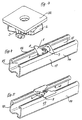
- FIGs 1 and 2 is an essential part of the Fastening device according to the invention shown, namely the mounting part 1 and the armature part 2, the mounting part 1 consists of sheet metal, which is substantially flat with two arms 3, by cranking the corresponding Section of the sheet metal part are created and their free ends 4 with a rubber ring pulling them together are connected, this rubber ring 5 also serves the To hold anchor part 2 on the mounting part 1.
- a central A bore is provided in the anchor part 2, into which a threaded bolt 7 can be screwed for fastening third components.
- Fig. 1 is the better overview because of Threaded bolt 7 not shown.
- the mounting part 1 has a central bore 8 through which protrudes after mounting the threaded bolt 7. It is also on the sheet-like structure 1 on diagonally facing away from each other Place a stop tab 9 each.
- the arms 3 point each have a recess 11 into which one on the armature part 2 arranged elevation 12 engages. To the rubber ring in the hold desired position are on the arms 3 to Notches 13 receiving rubber ring are provided. To the free ends of the arms 3 are following the Recesses 11 ramps 10 in these cranked sheet metal parts molded in order to thereby raise the elevations 12th easier to slide into the recesses 11.
- a rail 14 serving as a basic component is C-shaped Cross-section shown, which on walls, ceilings or other structural elements is attached to other To connect components with it.
- the one for this Parts used above are shown in Fig. 4 in the Assembly position shown, in the anchor part 2 through the slot 15 the rail is pushed and in which the mounting part 1 on a Clamping surface 16 of the support rail 14 rests.
- the Stop flaps 9 run parallel to the legs 17 the support rail 14.
- the clamping position of the invention Fastening device shown after which the structural part 1 in its level was rotated by about 60 ° so that the Stop tabs 9 on the legs 17 of the support rail 14 attacks.
- the anchor part 2 rotated due to the arms 3 engages under serving as abutment 18 edges of the C-shaped Carrier rail 14, those shown in Fig. 2 Toothed strips 19 this abutment 18 directly opposite.
- the cross section running parallel to the structural part 1 through the anchor part 2 diamond-shaped thus has the shape of a Parallelogram, and it is also the edges 21 that when rotating first in contact with the abutment 18 come, rounded. Due to the parallelogram shape the anchor part 2 can only be rotated by about 60 degrees, so that the toothing strips 19 the abutment 18th directly opposite.
- Fig. 3 is on the components shown in Fig. 1, namely the Anchor part 2 and the mounting part covered here with arms 3 one plate 22 attached, for attachment of others Individual parts.
- a plate 22 is of course a high one Deflection stiffness given.
Landscapes
- Engineering & Computer Science (AREA)
- General Engineering & Computer Science (AREA)
- Mechanical Engineering (AREA)
- Clamps And Clips (AREA)
- Seal Device For Vehicle (AREA)
- Joining Of Building Structures In Genera (AREA)
- Paper (AREA)
- Basic Packing Technique (AREA)
- Connection Of Plates (AREA)
- Control And Other Processes For Unpacking Of Materials (AREA)
- Window Of Vehicle (AREA)
Applications Claiming Priority (2)
| Application Number | Priority Date | Filing Date | Title |
|---|---|---|---|
| DE19904222 | 1999-02-03 | ||
| DE19904222 | 1999-02-03 |
Publications (3)
| Publication Number | Publication Date |
|---|---|
| EP1026415A2 true EP1026415A2 (fr) | 2000-08-09 |
| EP1026415A3 EP1026415A3 (fr) | 2002-01-02 |
| EP1026415B1 EP1026415B1 (fr) | 2006-05-10 |
Family
ID=7896223
Family Applications (1)
| Application Number | Title | Priority Date | Filing Date |
|---|---|---|---|
| EP00102342A Expired - Lifetime EP1026415B1 (fr) | 1999-02-03 | 2000-02-03 | Dispositif de fixation |
Country Status (5)
| Country | Link |
|---|---|
| EP (1) | EP1026415B1 (fr) |
| AT (1) | ATE325954T1 (fr) |
| DE (2) | DE10004657A1 (fr) |
| DK (1) | DK1026415T3 (fr) |
| ES (1) | ES2264409T3 (fr) |
Cited By (6)
| Publication number | Priority date | Publication date | Assignee | Title |
|---|---|---|---|---|
| EP1338805A3 (fr) * | 2002-02-21 | 2004-01-21 | Schwarz Verbindungs-Systeme GmbH | Insert de fixation amovible pour gorge de retenue |
| WO2005059380A1 (fr) * | 2003-12-17 | 2005-06-30 | A. Raymond & Cie | Dispositif de connexion d'une piece support et d'une piece rapportee |
| DE102009000757A1 (de) * | 2009-02-11 | 2010-08-19 | Hilti Aktiengesellschaft | Einteiliges Befestigungselement zur Anordnung eines Stangenelementes an einer Montageschiene |
| CN104320058A (zh) * | 2014-10-09 | 2015-01-28 | 厦门天环能源科技有限公司 | 一种太阳能电池板固定装置 |
| DE102018001594A1 (de) * | 2018-03-01 | 2019-09-05 | A. Raymond Et Cie | Befestigungsvorrichtung |
| WO2021211304A1 (fr) * | 2020-04-15 | 2021-10-21 | Panduit Corp. | Ensemble potence souple |
Families Citing this family (4)
| Publication number | Priority date | Publication date | Assignee | Title |
|---|---|---|---|---|
| DE10036478A1 (de) * | 2000-07-25 | 2002-02-07 | Edgar Emil Sinn | Schnellbefestigungselement |
| DE102017103771A1 (de) | 2017-02-23 | 2018-08-23 | Secura Services Ag | Befestigungsvorrichtung und Befestigungsbaugruppe |
| DE102018206849B4 (de) * | 2018-05-03 | 2021-08-12 | Icotek Project Gmbh & Co. Kg | Vorrichtung zur klemmenden Befestigung |
| EP3916248A1 (fr) | 2020-05-27 | 2021-12-01 | Hilti Aktiengesellschaft | Connecteur de canal d'entretoise rotatif à ailettes |
Citations (3)
| Publication number | Priority date | Publication date | Assignee | Title |
|---|---|---|---|---|
| FR2468784A1 (fr) | 1979-10-30 | 1981-05-08 | Telemecanique Electrique | Ecrou coulissant pour profile en forme de c |
| US4666355A (en) | 1986-08-04 | 1987-05-19 | Usg Industries, Inc. | Top grip lock nut assembly |
| DE4243185A1 (de) | 1992-12-19 | 1994-06-23 | Hilti Ag | Befestigungsvorrichtung |
Family Cites Families (4)
| Publication number | Priority date | Publication date | Assignee | Title |
|---|---|---|---|---|
| DE19635632A1 (de) * | 1996-09-03 | 1998-03-05 | Hilti Ag | Befestigungselement für Profilschienen |
| DE29703027U1 (de) * | 1997-02-20 | 1998-06-18 | Fischerwerke Artur Fischer Gmbh & Co Kg, 72178 Waldachtal | Hammerkopfschraube für eine Deckenbefestigung |
| DE19722778C1 (de) * | 1997-06-02 | 1998-05-14 | Kratzer F Mefa Duebel Gmbh | Verankerungseinheit |
| EP0950821B1 (fr) * | 1998-04-17 | 2007-01-10 | Erico International Corporation | Dispositif et méthode de connexion d'une tige filetée à un profilé |
-
2000
- 2000-02-03 DE DE10004657A patent/DE10004657A1/de not_active Withdrawn
- 2000-02-03 DK DK00102342T patent/DK1026415T3/da active
- 2000-02-03 DE DE50012707T patent/DE50012707D1/de not_active Expired - Lifetime
- 2000-02-03 EP EP00102342A patent/EP1026415B1/fr not_active Expired - Lifetime
- 2000-02-03 ES ES00102342T patent/ES2264409T3/es not_active Expired - Lifetime
- 2000-02-03 AT AT00102342T patent/ATE325954T1/de not_active IP Right Cessation
Patent Citations (3)
| Publication number | Priority date | Publication date | Assignee | Title |
|---|---|---|---|---|
| FR2468784A1 (fr) | 1979-10-30 | 1981-05-08 | Telemecanique Electrique | Ecrou coulissant pour profile en forme de c |
| US4666355A (en) | 1986-08-04 | 1987-05-19 | Usg Industries, Inc. | Top grip lock nut assembly |
| DE4243185A1 (de) | 1992-12-19 | 1994-06-23 | Hilti Ag | Befestigungsvorrichtung |
Cited By (11)
| Publication number | Priority date | Publication date | Assignee | Title |
|---|---|---|---|---|
| EP1338805A3 (fr) * | 2002-02-21 | 2004-01-21 | Schwarz Verbindungs-Systeme GmbH | Insert de fixation amovible pour gorge de retenue |
| WO2005059380A1 (fr) * | 2003-12-17 | 2005-06-30 | A. Raymond & Cie | Dispositif de connexion d'une piece support et d'une piece rapportee |
| KR100789326B1 (ko) * | 2003-12-17 | 2007-12-28 | 아. 레이몽 에 씨에 | 부착편에 지지 부재를 연결하기 위한 연결 장치 |
| CN100458192C (zh) * | 2003-12-17 | 2009-02-04 | A·雷蒙公司 | 用于连接支承件和附件的装置 |
| US7568868B2 (en) | 2003-12-17 | 2009-08-04 | A. Raymond Et Cie | Device for connecting a support element to an add-on piece |
| DE102009000757A1 (de) * | 2009-02-11 | 2010-08-19 | Hilti Aktiengesellschaft | Einteiliges Befestigungselement zur Anordnung eines Stangenelementes an einer Montageschiene |
| CN104320058A (zh) * | 2014-10-09 | 2015-01-28 | 厦门天环能源科技有限公司 | 一种太阳能电池板固定装置 |
| DE102018001594A1 (de) * | 2018-03-01 | 2019-09-05 | A. Raymond Et Cie | Befestigungsvorrichtung |
| WO2021211304A1 (fr) * | 2020-04-15 | 2021-10-21 | Panduit Corp. | Ensemble potence souple |
| US11384814B2 (en) | 2020-04-15 | 2022-07-12 | Panduit Corp. | Compliant hanger assembly |
| AU2021255469B2 (en) * | 2020-04-15 | 2026-01-08 | Panduit Corp. | Compliant hanger assembly |
Also Published As
| Publication number | Publication date |
|---|---|
| EP1026415A3 (fr) | 2002-01-02 |
| EP1026415B1 (fr) | 2006-05-10 |
| ES2264409T3 (es) | 2007-01-01 |
| ATE325954T1 (de) | 2006-06-15 |
| DE50012707D1 (de) | 2006-06-14 |
| DE10004657A1 (de) | 2000-08-10 |
| DK1026415T3 (da) | 2006-08-21 |
Similar Documents
| Publication | Publication Date | Title |
|---|---|---|
| EP2440860B1 (fr) | Adaptateur pour profilés de support | |
| EP1826507A2 (fr) | Dispositif de fixation pour la fixation de panneaux solaires sur un rail de montage | |
| DE8715256U1 (de) | Montageschieneneinheit | |
| DE19912474C2 (de) | Befestigungsanordnung für die Anbringung eines Bauteils an einer C-förmigen Halteschiene | |
| EP1538349B1 (fr) | Dispositif de fixation | |
| EP1026415B1 (fr) | Dispositif de fixation | |
| EP3787137A1 (fr) | Dispositif de raccordement, garniture de raccordement et chemin de câbles | |
| EP1767793A2 (fr) | Dispositif de fixation pour la fixation des panneaux solaires à un rail d'assemblage | |
| EP1222406B1 (fr) | Element de retenue pour vis a tete | |
| DE19722778C1 (de) | Verankerungseinheit | |
| DE19652027C2 (de) | Montageschiene zur Befestigung von Rohren o. dgl. Gegenständen | |
| DE102012004773A1 (de) | Vorrichtung für die Halterung von Photovoltaikmodulen auf Freiflächen | |
| EP3658788A1 (fr) | Dispositif de fixation pour fixation à un rail de montage | |
| EP2803779A1 (fr) | Système de fixation d'un rail | |
| EP0162063B1 (fr) | Dispositif de fixation | |
| DE4303731C2 (de) | Montageelement und Verfahren zu seiner Befestigung an Profilträgern | |
| DE4021245C2 (fr) | ||
| EP1114935A2 (fr) | Noeud d'assemblage pour perpendiculairement connecter un rail de mountage à un autre support | |
| EP0905425A2 (fr) | Dispositif de fixation | |
| DE4238703A1 (de) | Verbindungsanordnung für Montagebauteile, insbesondere zur Vorwandmontage von Sanitärbauteilen | |
| EP3402993B1 (fr) | Systeme de montage dote de rail de montage et ecrou de retenue en saillie | |
| DE3941097C1 (en) | Cable channel or tray support - has coupling element fixable from above in form of shaft fitting selectable slots and with projection to act like hook | |
| EP1371530B1 (fr) | Dispositif de fixation | |
| DE29621873U1 (de) | Montagesystem für die Anbringung eines Bauteils an einer C-förmigen Halteschiene sowie Drehwerkzeug dafür | |
| DE102008035396A1 (de) | Haltevorrichtung für ein Heiz- oder Lüftungsgerät |
Legal Events
| Date | Code | Title | Description |
|---|---|---|---|
| PUAI | Public reference made under article 153(3) epc to a published international application that has entered the european phase |
Free format text: ORIGINAL CODE: 0009012 |
|
| AK | Designated contracting states |
Kind code of ref document: A2 Designated state(s): AT BE CH CY DE DK ES FI FR GB GR IE IT LI LU MC NL PT SE |
|
| AX | Request for extension of the european patent |
Free format text: AL;LT;LV;MK;RO;SI |
|
| PUAL | Search report despatched |
Free format text: ORIGINAL CODE: 0009013 |
|
| AK | Designated contracting states |
Kind code of ref document: A3 Designated state(s): AT BE CH CY DE DK ES FI FR GB GR IE IT LI LU MC NL PT SE |
|
| AX | Request for extension of the european patent |
Free format text: AL;LT;LV;MK;RO;SI |
|
| 17P | Request for examination filed |
Effective date: 20020702 |
|
| AKX | Designation fees paid |
Free format text: AT BE CH CY DE DK ES FI FR GB GR IE IT LI LU MC NL PT SE |
|
| 17Q | First examination report despatched |
Effective date: 20050315 |
|
| GRAP | Despatch of communication of intention to grant a patent |
Free format text: ORIGINAL CODE: EPIDOSNIGR1 |
|
| GRAS | Grant fee paid |
Free format text: ORIGINAL CODE: EPIDOSNIGR3 |
|
| GRAA | (expected) grant |
Free format text: ORIGINAL CODE: 0009210 |
|
| AK | Designated contracting states |
Kind code of ref document: B1 Designated state(s): AT BE CH CY DE DK ES FI FR GB GR IE IT LI LU MC NL PT SE |
|
| PG25 | Lapsed in a contracting state [announced via postgrant information from national office to epo] |
Ref country code: IT Free format text: LAPSE BECAUSE OF FAILURE TO SUBMIT A TRANSLATION OF THE DESCRIPTION OR TO PAY THE FEE WITHIN THE PRE;WARNING: LAPSES OF ITALIAN PATENTS WITH EFFECTIVE DATE BEFORE 2007 MAY HAVE OCCURRED AT ANY TIME BEFORE 2007. THE CORRECT EFFECTIVE DATE MAY BE DIFFERENT FROM THE ONE RECORDED.SCRIBED TIME-LIMIT Effective date: 20060510 Ref country code: GB Free format text: LAPSE BECAUSE OF FAILURE TO SUBMIT A TRANSLATION OF THE DESCRIPTION OR TO PAY THE FEE WITHIN THE PRESCRIBED TIME-LIMIT Effective date: 20060510 Ref country code: IE Free format text: LAPSE BECAUSE OF FAILURE TO SUBMIT A TRANSLATION OF THE DESCRIPTION OR TO PAY THE FEE WITHIN THE PRESCRIBED TIME-LIMIT Effective date: 20060510 Ref country code: FI Free format text: LAPSE BECAUSE OF FAILURE TO SUBMIT A TRANSLATION OF THE DESCRIPTION OR TO PAY THE FEE WITHIN THE PRESCRIBED TIME-LIMIT Effective date: 20060510 |
|
| REG | Reference to a national code |
Ref country code: GB Ref legal event code: FG4D Free format text: NOT ENGLISH |
|
| REG | Reference to a national code |
Ref country code: CH Ref legal event code: EP |
|
| REF | Corresponds to: |
Ref document number: 50012707 Country of ref document: DE Date of ref document: 20060614 Kind code of ref document: P |
|
| REG | Reference to a national code |
Ref country code: IE Ref legal event code: FG4D Free format text: LANGUAGE OF EP DOCUMENT: GERMAN |
|
| PG25 | Lapsed in a contracting state [announced via postgrant information from national office to epo] |
Ref country code: SE Free format text: LAPSE BECAUSE OF FAILURE TO SUBMIT A TRANSLATION OF THE DESCRIPTION OR TO PAY THE FEE WITHIN THE PRESCRIBED TIME-LIMIT Effective date: 20060810 |
|
| REG | Reference to a national code |
Ref country code: DK Ref legal event code: T3 |
|
| PG25 | Lapsed in a contracting state [announced via postgrant information from national office to epo] |
Ref country code: PT Free format text: LAPSE BECAUSE OF FAILURE TO SUBMIT A TRANSLATION OF THE DESCRIPTION OR TO PAY THE FEE WITHIN THE PRESCRIBED TIME-LIMIT Effective date: 20061010 |
|
| ET | Fr: translation filed | ||
| GBV | Gb: ep patent (uk) treated as always having been void in accordance with gb section 77(7)/1977 [no translation filed] |
Effective date: 20060510 |
|
| REG | Reference to a national code |
Ref country code: IE Ref legal event code: FD4D |
|
| REG | Reference to a national code |
Ref country code: ES Ref legal event code: FG2A Ref document number: 2264409 Country of ref document: ES Kind code of ref document: T3 |
|
| PG25 | Lapsed in a contracting state [announced via postgrant information from national office to epo] |
Ref country code: CH Free format text: LAPSE BECAUSE OF NON-PAYMENT OF DUE FEES Effective date: 20070228 Ref country code: LI Free format text: LAPSE BECAUSE OF NON-PAYMENT OF DUE FEES Effective date: 20070228 Ref country code: MC Free format text: LAPSE BECAUSE OF NON-PAYMENT OF DUE FEES Effective date: 20070228 |
|
| PLBE | No opposition filed within time limit |
Free format text: ORIGINAL CODE: 0009261 |
|
| STAA | Information on the status of an ep patent application or granted ep patent |
Free format text: STATUS: NO OPPOSITION FILED WITHIN TIME LIMIT |
|
| 26N | No opposition filed |
Effective date: 20070213 |
|
| REG | Reference to a national code |
Ref country code: CH Ref legal event code: PL |
|
| BERE | Be: lapsed |
Owner name: MEFA BEFESTIGUNGS- UND MONTAGESYSTEME G.M.B.H. Effective date: 20070228 |
|
| PG25 | Lapsed in a contracting state [announced via postgrant information from national office to epo] |
Ref country code: BE Free format text: LAPSE BECAUSE OF NON-PAYMENT OF DUE FEES Effective date: 20070228 |
|
| PG25 | Lapsed in a contracting state [announced via postgrant information from national office to epo] |
Ref country code: GR Free format text: LAPSE BECAUSE OF FAILURE TO SUBMIT A TRANSLATION OF THE DESCRIPTION OR TO PAY THE FEE WITHIN THE PRESCRIBED TIME-LIMIT Effective date: 20060811 |
|
| PG25 | Lapsed in a contracting state [announced via postgrant information from national office to epo] |
Ref country code: AT Free format text: LAPSE BECAUSE OF NON-PAYMENT OF DUE FEES Effective date: 20070203 |
|
| PG25 | Lapsed in a contracting state [announced via postgrant information from national office to epo] |
Ref country code: CY Free format text: LAPSE BECAUSE OF FAILURE TO SUBMIT A TRANSLATION OF THE DESCRIPTION OR TO PAY THE FEE WITHIN THE PRESCRIBED TIME-LIMIT Effective date: 20060510 Ref country code: LU Free format text: LAPSE BECAUSE OF NON-PAYMENT OF DUE FEES Effective date: 20070203 |
|
| PGFP | Annual fee paid to national office [announced via postgrant information from national office to epo] |
Ref country code: DK Payment date: 20130221 Year of fee payment: 14 |
|
| REG | Reference to a national code |
Ref country code: DK Ref legal event code: EBP Effective date: 20140228 |
|
| PG25 | Lapsed in a contracting state [announced via postgrant information from national office to epo] |
Ref country code: DK Free format text: LAPSE BECAUSE OF NON-PAYMENT OF DUE FEES Effective date: 20140228 |
|
| REG | Reference to a national code |
Ref country code: DE Ref legal event code: R082 Ref document number: 50012707 Country of ref document: DE Representative=s name: PATENTANWAELTE SCHUSTER, MUELLER & PARTNER MBB, DE |
|
| REG | Reference to a national code |
Ref country code: FR Ref legal event code: PLFP Year of fee payment: 17 |
|
| PGFP | Annual fee paid to national office [announced via postgrant information from national office to epo] |
Ref country code: ES Payment date: 20160223 Year of fee payment: 17 |
|
| PGFP | Annual fee paid to national office [announced via postgrant information from national office to epo] |
Ref country code: NL Payment date: 20160222 Year of fee payment: 17 Ref country code: FR Payment date: 20160222 Year of fee payment: 17 |
|
| REG | Reference to a national code |
Ref country code: NL Ref legal event code: MM Effective date: 20170301 |
|
| PG25 | Lapsed in a contracting state [announced via postgrant information from national office to epo] |
Ref country code: NL Free format text: LAPSE BECAUSE OF NON-PAYMENT OF DUE FEES Effective date: 20170301 |
|
| REG | Reference to a national code |
Ref country code: FR Ref legal event code: ST Effective date: 20171031 |
|
| PG25 | Lapsed in a contracting state [announced via postgrant information from national office to epo] |
Ref country code: FR Free format text: LAPSE BECAUSE OF NON-PAYMENT OF DUE FEES Effective date: 20170228 |
|
| REG | Reference to a national code |
Ref country code: ES Ref legal event code: FD2A Effective date: 20180704 |
|
| PG25 | Lapsed in a contracting state [announced via postgrant information from national office to epo] |
Ref country code: ES Free format text: LAPSE BECAUSE OF NON-PAYMENT OF DUE FEES Effective date: 20170204 |
|
| PGFP | Annual fee paid to national office [announced via postgrant information from national office to epo] |
Ref country code: DE Payment date: 20190109 Year of fee payment: 20 Ref country code: IT Payment date: 20190222 Year of fee payment: 20 |
|
| REG | Reference to a national code |
Ref country code: DE Ref legal event code: R071 Ref document number: 50012707 Country of ref document: DE |