EP1026532A1 - Baugruppe aus einem optischen Element und einer Fassung - Google Patents
Baugruppe aus einem optischen Element und einer Fassung Download PDFInfo
- Publication number
- EP1026532A1 EP1026532A1 EP00101031A EP00101031A EP1026532A1 EP 1026532 A1 EP1026532 A1 EP 1026532A1 EP 00101031 A EP00101031 A EP 00101031A EP 00101031 A EP00101031 A EP 00101031A EP 1026532 A1 EP1026532 A1 EP 1026532A1
- Authority
- EP
- European Patent Office
- Prior art keywords
- assembly according
- joining element
- socket
- optical element
- membrane
- Prior art date
- Legal status (The legal status is an assumption and is not a legal conclusion. Google has not performed a legal analysis and makes no representation as to the accuracy of the status listed.)
- Granted
Links
- 230000003287 optical effect Effects 0.000 title claims abstract description 36
- 238000005304 joining Methods 0.000 claims description 37
- 239000012528 membrane Substances 0.000 claims description 37
- 238000005452 bending Methods 0.000 claims description 7
- 238000000034 method Methods 0.000 claims description 7
- 238000004026 adhesive bonding Methods 0.000 claims description 5
- 238000005476 soldering Methods 0.000 claims description 4
- 238000003466 welding Methods 0.000 claims description 4
- 239000000463 material Substances 0.000 claims description 3
- 238000005516 engineering process Methods 0.000 claims description 2
- 230000010354 integration Effects 0.000 claims description 2
- 230000002093 peripheral effect Effects 0.000 claims description 2
- 239000002520 smart material Substances 0.000 claims description 2
- 239000002184 metal Substances 0.000 claims 1
- 241000219739 Lens Species 0.000 description 34
- 240000004322 Lens culinaris Species 0.000 description 3
- 229910045601 alloy Inorganic materials 0.000 description 3
- 239000000956 alloy Substances 0.000 description 3
- 239000000853 adhesive Substances 0.000 description 2
- 230000001070 adhesive effect Effects 0.000 description 2
- 230000035882 stress Effects 0.000 description 2
- 229910001069 Ti alloy Inorganic materials 0.000 description 1
- 230000000712 assembly Effects 0.000 description 1
- 238000000429 assembly Methods 0.000 description 1
- 238000011161 development Methods 0.000 description 1
- 230000018109 developmental process Effects 0.000 description 1
- 238000005530 etching Methods 0.000 description 1
- 239000003292 glue Substances 0.000 description 1
- 238000004519 manufacturing process Methods 0.000 description 1
- 229910001000 nickel titanium Inorganic materials 0.000 description 1
- 239000012858 resilient material Substances 0.000 description 1
- 229910001285 shape-memory alloy Inorganic materials 0.000 description 1
- 239000010935 stainless steel Substances 0.000 description 1
- 229910001220 stainless steel Inorganic materials 0.000 description 1
- 230000008646 thermal stress Effects 0.000 description 1
Images


Classifications
-
- G—PHYSICS
- G03—PHOTOGRAPHY; CINEMATOGRAPHY; ANALOGOUS TECHNIQUES USING WAVES OTHER THAN OPTICAL WAVES; ELECTROGRAPHY; HOLOGRAPHY
- G03F—PHOTOMECHANICAL PRODUCTION OF TEXTURED OR PATTERNED SURFACES, e.g. FOR PRINTING, FOR PROCESSING OF SEMICONDUCTOR DEVICES; MATERIALS THEREFOR; ORIGINALS THEREFOR; APPARATUS SPECIALLY ADAPTED THEREFOR
- G03F7/00—Photomechanical, e.g. photolithographic, production of textured or patterned surfaces, e.g. printing surfaces; Materials therefor, e.g. comprising photoresists; Apparatus specially adapted therefor
- G03F7/70—Microphotolithographic exposure; Apparatus therefor
- G03F7/708—Construction of apparatus, e.g. environment aspects, hygiene aspects or materials
- G03F7/70808—Construction details, e.g. housing, load-lock, seals or windows for passing light in or out of apparatus
- G03F7/70825—Mounting of individual elements, e.g. mounts, holders or supports
-
- G—PHYSICS
- G02—OPTICS
- G02B—OPTICAL ELEMENTS, SYSTEMS OR APPARATUS
- G02B7/00—Mountings, adjusting means, or light-tight connections, for optical elements
- G02B7/02—Mountings, adjusting means, or light-tight connections, for optical elements for lenses
- G02B7/026—Mountings, adjusting means, or light-tight connections, for optical elements for lenses using retaining rings or springs
Definitions
- the invention relates to an assembly consisting of an optical element and a version according to the preamble of claim 1 Art.
- US 5,428,482 relates to the decoupling of an optical Element from a frame by elastic beam-like Links between the optical element and the frame.
- EP 0 230 277 A2 relates to a precision lens attachment, also elastic bending elements in the form of beams are provided between the optical element and the socket. Due to the elastic bending elements, radial flexibility should be achieved to compensate for thermal stresses.
- EP 0 243 893 B1 in which a lens attachment is described for position lenses, a variety of bending devices that are designed like leaf springs are holding a lens as an optical element on a frame.
- the present invention has for its object a Connection technology between an optical element and a to create this holding frame, being the optical element thus connected to the socket via elastic connections is that an at least extensive freedom from tension or Low tension and thus a reduction in surface deformation of the optical element in a geometrically simple Design is created.
- this task is characterized by Part of claim 1 mentioned features solved.
- the membrane-like joining element according to the invention Due to the membrane-like joining element according to the invention high elasticity and flexibility in the z direction during assembly, i.e. in the direction of the optical axis. On in this way, the optical element can be stress-free exactly align on the joining element. Then becomes a fixed one Connection between the joining element and the optical element manufactured and according to the invention a stiff, a moment transmitting connection, so practically the one that arises Bending angle between the joining element and the optical Element held, with which not easily one Adjust further bending if a load occurs can, i.e. Angle changes are no longer possible. Through the Establishing a firm connection will be at the junction the degrees of freedom are blocked. This is included occurring external forces and moments a buckling stress whose rigidity is significantly greater than that of the pure bend, creating the required natural frequency and Stability is ensured.
- a simple design to solve the problem Task can be that the joining element a membrane ring or several ring segments, which to a closed membrane ring. On this will result in a significant reduction in surface deformation of the optical element reached.
- An annular socket 1 is on the inside with a Ring paragraph 2 provided, the one at least approximately the bending line of a joining element 4 correspondingly running support contour 3 has.
- On the support contour 3 is used as a joining element a membrane ring 4 placed and positive and / or non-positive (e.g. by welding, soldering or gluing) firmly with the socket 1 connected.
- a membrane ring 4 placed and positive and / or non-positive (e.g. by welding, soldering or gluing) firmly with the socket 1 connected.
- From the membrane ring 4 protrude from its inner circumference Variety of tabs 6 inside.
- the tabs 6 serve as Support for a lens 7 as an optical element.
- the membrane ring 4 with the tabs 6 is made of a resilient material, e.g. one very thin sheet with a thickness of 0.3 to 0.5 mm.
- the membrane ring 4 with the tabs 6, e.g. cold-rolled strips made of stainless steel titanium alloys or nitinol-nickel-titanium alloys, which is also called a memory alloy can be used.
- a memory alloy e.g. titanium alloys or nitinol-nickel-titanium alloys, which is also called a memory alloy.
- an alloy with super elastic properties is intended for the Suitable purpose because these alloys have large deformations enable in a small space.
- the joining element, i.e. the membrane ring 4 can also with the integration or application of a intelligent materials (smart materials, e.g. shape memory - or piezoelectric elements), so that influencing the state of deformation by supplying energy of the optical element is possible, or detected can be.
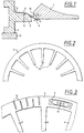
- the membrane ring can be produced by an etching technique be, which is particularly advantageous if he is provided with numerous contours, e.g. from FIG. 3 evident.
- FIG. 3 shows a membrane ring 4 with tabs 6, wherein in the membrane ring 4 from the outer circumference and from the inner circumference alternately radial or tangential slots 8 are formed are.
- the slots 8 are used to warp the membrane ring 4 to be avoided if e.g. by welding with the resulting tensions associated with version 1 becomes.
- the membrane ring 4 also with relief pockets distributed over the circumference 9 be provided.
- the relief pockets 9 can be arbitrarily designed with e.g. extending in the circumferential direction Grooves of different cross-section and with between the relief bores lying in the grooves 10.
- the assembly of the optical assembly can be done easily and done very precisely with regard to the positioning of the lens 7.
- version 1 is based on a rigid flat counter flange 11 clamped. Then will the membrane ring 4 on the support contour 3 e.g. by welding attached.
- the lens 7 is on the Lugs 6 placed and in a known directional joining process, aligned. Is the straightening process finished, due to the high elasticity of the membrane ring 4 or the tabs 6 a stress and deformation-free support of the lens 7 is achieved can be done e.g. about gluing or soldering to one Connection 12 a rigid connection between the lens 7 and the membrane ring 4 or its tabs 6.
- connection 12 Through the connection 12 produced in this way, the so can also transmit moments, receives the membrane ring 4 with the Brackets 6 have a high rigidity due to the curved geometric shape after the fixed connection with the lens. It there is practically a fixed angle ⁇ in the area of the connection 12, who can no longer change. As a result of that the angle ⁇ can no longer change with one Occurrence of forces for the membrane ring 4 or the fins 6 only the possibility of a slight S-shaped bend or bulge. In this way it has been achieved that the Assembly a very large deformation possible, but after the joining process a high degree of rigidity is given, so that positioning the lens 7 with sufficient accuracy and Stability is achieved.
- the geometric design of the joining element e.g. as a membrane ring 4 with tabs 6 can depend on the application be varied to a high degree.
- the geometric Design of the membrane ring 4 can be defined once and then remain the same for a lens in its entirety. It is then only necessary to have the required diameter to adjust the lenses.
- the number and shape of the tabs 6 depends on the lens mass and the sheet thickness and leaves also vary.
- FIG. 4 shows a production from several individual segments then when you reach a very high precision would like and different elasticities due to the known Anisotopy of rolled sheets resulting in an uneven Deflection of the membrane ring 4 and / or the tabs 6 leads, should be avoided.
- FIG Diaphragm ring 4 shown, for example with only 6 incisions 13 is provided, whereby only 6 tab-like contact surfaces are formed for the lens 7.
- the pins 16 are distributed over the circumference and with their Longitudinal axes arranged in the z-direction Support ring 17 used.
- the support ring 17 is in the outer region with the version 1, e.g. connected by screws. At the same time, this type of connection can also be used to attach the Form membrane ring 4 with the socket.
- the pins 16 have an L-shape, with its angled Part extends perpendicular to the z-axis and with the free end e.g. by gluing to the peripheral wall of the lens 7 connected is. As soon as the lens 7 is aligned in the z direction is, the pins 16 in the holes of the support ring 17th fixed in their positions, which e.g. can be done in that the holes adhesive is introduced.
- the increase in stiffness shown in FIG. 5 in the z direction is intended for an assembly that is arranged vertically is.
- FIG. 6 shows an arrangement, the lens 7 being vertical is arranged and the z-axis extends horizontally. Out this is in addition to the membrane ring 4 as a joining element a second membrane ring 4 'is provided on the Membrane ring 4 opposite side of the lens 7 also via a stiff, moment-transmitting connection 12 ' the lens is connected. Also in this embodiment are centering members in the form of pins 16 'provided distributed over the circumference attack on the outer circumference of the lens 7. In this case, the pins 16 'have an inverted T shape and are glued to the circumference of the lens 7 via the T-bars. The pins 16 'are in turn in bores of a support ring 17' used, which after the alignment of the lens 7 with a Adhesive to create a firm connection between the Pins 16 'and the support ring 17' are filled.
- a retaining ring 18 through which the membrane ring 4 'simultaneously with the support ring 17' and the Membrane ring 4 is firmly connected to the socket 1.
- FIGS. 7 to 11 Different types are shown in FIGS. 7 to 11, for example of tabs 6 of the membrane ring 4 and 4 'shown.
- Figure 7 shows a shape in which the tab in the longitudinal direction is provided with a structure 19.
- FIG. 8 shows one in the area of the connection 12 with the lens 7 Comb structure or incisions 20. At the same time, the figure shows 8 also an embodiment of a tab 6 with an area of a reduced width between the membrane ring 4 and the connection 12 in the front area.
- Figure 9 shows an even larger constriction of a tab 6 conical course to its front end, that as a connection 12 with the lens 7 is used.
- tab 6 in the area of connection 12 with the lens 7 may be provided with an etched lattice structure 21 can.
- the etched lattice structure 21 has the job of a better one To achieve bonding to the connection 12 or so it is not necessary to dose the glue extremely precisely must, since this then evade into the lattice structure 21 can.
- such a lattice structure 21 also possible with other tab shapes.
- FIG. 10 shows a similar configuration of a tab 6 as in FIG. 9, only the constricted area is not so strongly emphasized and the support area for Connection 12 has an approximate elliptical shape with a larger ellipse axis running in the radial direction.
- Figure 11 shows a simple rectangular configuration (also in plan view) of a tab 6. While e.g. wide tabs, such as the tabs shown in Figures 7 and 11 6, with a thinner sheet thickness, e.g. 0.1 to 0.3 mm, will produce, you will narrow long tabs 6 with a larger sheet thickness, e.g. 0.3 to 0.5 mm.
Landscapes
- Physics & Mathematics (AREA)
- General Physics & Mathematics (AREA)
- Health & Medical Sciences (AREA)
- Engineering & Computer Science (AREA)
- Environmental & Geological Engineering (AREA)
- Epidemiology (AREA)
- Public Health (AREA)
- Optics & Photonics (AREA)
- Lens Barrels (AREA)
- Mounting And Adjusting Of Optical Elements (AREA)
Abstract
Description
- Figur 1
- ausschnittsweise einen Schnitt durch eine Baugruppe mit einer Fassung und einer Linse als optischem Element,
- Figur 2
- ausschnittsweise eine Draufsicht auf ein membranartiges Fügeelement mit Laschen,
- Figur 3
- eine weitere Ausgestaltung eines membranartigen Fügeelementes in der Draufsicht (ausschnittsweise),
- Figur 4
- eine Draufsicht auf eine dritte Ausgestaltung eines membranartigen Fügeelementes,
- Figur 5
- ausschnittsweise einen Schnitt durch eine weitere Ausgestaltung einer Baugruppe mit einer Fassung und einem optischen Element,
- Figur 6
- ausschnittsweise einen Schnitt durch eine dritte Ausgestaltung einer Baugruppe mit einer Fassung und einer Linse als optischem Element in horizontaler Anordnung der Linse,
- Figur 7 bis 11
- verschiedene Ausgestaltungen von Laschen eines Membranringes als Fügeelement.
Claims (20)
- Baugruppe aus einem optischen Element und einer Fassung, bei der das optische Element über elastische Verbindungsglieder direkt oder über ein oder mehrere Zwischenglieder mit der Fassung verbunden ist, dadurch gekennzeichnet, daß das oder die Verbindungsglieder wenigstens ein membranartiges Fügeelement (4) aufweist, welches im äußeren Bereich mit der Fassung (1) oder mit dem oder den Zwischengliedern und im inneren Bereich über eine steife, Momente übertragende Verbindung (12) mit dem optischen Element (7) verbunden ist.
- Baugruppe nach Anspruch 1, dadurch gekennzeichnet, daß das Fügeelement einen Membranring (4) oder mehrere Membranringsegmente (15) aufweist, die zu einem geschlossenen Membranring zusammensetzbar sind.
- Baugruppe nach Anspruch 1 oder 2, dadurch gekennzeichnet, daß das Fügeelement (4) am Innenumfang mit Laschen (6) versehen ist, auf denen das optische Element (7) aufliegt und über die die steife, Momente übertragende Verbindung (12) hergestellt ist.
- Baugruppe nach einem der Ansprüche 1 bis 3, dadurch gekennzeichnet, daß das Fügeelement (4) aus einem dünnen federartigen Blech besteht.
- Baugruppe nach einem der Ansprüche 1 bis 4, dadurch gekennzeichnet, daß die Verbindung (12) form- oder kraftschlüssig erfolgt, z.B. durch Schweißen, Löten, Kleben oder Klemmen.
- Baugruppe nach einem der Ansprüche 1 bis 5, dadurch gekennzeichnet, daß das Fügeelement (4) im äußeren Umfangsbereich, in welchem es mit dem Rahmen (1) oder ein oder mehreren Zwischengliedern verbunden ist, zur Deformationsentkopplung wenigstens annähernd in radialer oder tangentialer Richtung verlaufende Schlitze (8) aufweist.
- Baugruppe nach Anspruch 6, dadurch gekennzeichnet, daß sich bei Ausbildung des Fügeelementes als Membranring (4) die Schlitze (8) abwechselnd vom Außenumfang und vom Innenumfang aus erstrecken.
- Baugruppe nach einem der Ansprüche 1 bis 7, dadurch gekennzeichnet, daß das Fügeelement (4) wenigstens in dem Bereich, in dem es mit der Fassung (1) oder den ein oder mehreren Zwischengliedern verbunden ist mit Entlastungstaschen (9) versehen ist.
- Baugruppe nach einem der Ansprüche 1 bis 8, dadurch gekennzeichnet, daß die Fassung (1) oder ein Zwischenglied, mit welchem das Fügeelement (4) verbunden ist, im Bereich der Verbindung eine der Biegelinie des Fügeelementes entsprechende Auflagekontur (3) aufweist.
- Baugruppe nach einem der Ansprüche 1 bis 9, dadurch gekennzeichnet, daß das Fügeelement (4), insbesondere bei Ausbildung mit Laschen (6), im Bereich der steifen, ein Moment übertragenden Verbindung (12), welche durch Kleben oder Löten geschaffen ist, wenigstens teilweise mit einer Gitter-(21) oder Kammstruktur (20) versehen ist.
- Baugruppe nach einem der Ansprüche 3 bis 10, dadurch gekennzeichnet, daß die Laschen (6) auf ihren Oberflächen (19,20) strukturiert sind.
- Baugruppe nach einem der Ansprüche 3 bis 11, dadurch gekennzeichnet, daß die Laschen (6) über ihre Länge unterschiedliche Breiten aufweisen.
- Baugruppe nach einem der Ansprüche 1 bis 12, dadurch gekennzeichnet, daß das Fügeelement (4) mit der Integration oder Applikation eines intelligenten Werkstoffes (smart materials, z.B. Formgedächtnis - oder piezoelektrische Elemente) versehen ist.
- Baugruppe nach einem der Ansprüche 1 bis 12, dadurch gekennzeichnet, daß das Fügeelement (4) aus einem Material mit superelastischen Eigenschaften besteht.
- Baugruppe nach einem der Ansprüche 1 bis 14, dadurch gekennzeichnet, daß die Fassung (1) oder ein mit der Fassung verbundenes Glied mit einem Stützring (17) verbunden ist, aus welchem in dem Stützring (17) angeordnete Elemente (Stifte 16) ragen, die mit ihren freien Enden derart mit dem optischen Element (7) verbunden sind, daß sich eine Steifigkeitserhöhung senkrecht zur und/oder in Richtung der optischen Achse (z-Richtung) ergibt.
- Baugruppe nach Anspruch 15, dadurch gekennzeichnet, daß die Elemente (Stifte 16) in Bohrungen des Stützringes (17) eingeklebt oder mit einer anderen form- oder kraftschlüssigen Verbindungstechnik befestigt sind.
- Baugruppe nach einem der Ansprüche 1 bis 16, dadurch gekennzeichnet, daß das optische Element (7) durch ein zweites membranartiges Fügeelement (4'), das auf der von der Verbindung (12) mit dem ersten Fügeelement (4) abgewandten Seite angeordnet ist, über eine steife, Momente übertragende Verbindung (12'), gehalten ist.
- Baugruppe nach einem der Ansprüche 1 bis 17, dadurch gekennzeichnet, daß die Fassung (1) mit einem Zentrierbund (5) für das Fügeelement (4) versehen ist.
- Verfahren zum Verbinden eines optischen Elementes mit einer Fassung oder einem mit der Fassung verbundenen Zwischenglied, dadurch gekennzeichnet, daß ein membranartiges Fügeelement (4) an der Fassung (1) befestigt wird, wonach das optische Element (7) auf das Fügeelement (4) aufgelegt und durch einen Richtfügevorgang auf dem Fügeelement (4) ausgerichtet wird, wonach das optische Element (7) auf dem Fügeelement (4) durch eine steife, ein Moment übertragende Verbindung (12)fixiert wird.
- Verfahren nach Anspruch 19, dadurch gekennzeichnet, daß die Fassung (1) zur Montage auf einen steifen Gegenflansch (11) aufgespannt wird.
Applications Claiming Priority (2)
| Application Number | Priority Date | Filing Date | Title |
|---|---|---|---|
| DE19904152A DE19904152A1 (de) | 1999-02-03 | 1999-02-03 | Baugruppe aus einem optischen Element und einer Fassung |
| DE19904152 | 1999-02-03 |
Publications (2)
| Publication Number | Publication Date |
|---|---|
| EP1026532A1 true EP1026532A1 (de) | 2000-08-09 |
| EP1026532B1 EP1026532B1 (de) | 2003-09-17 |
Family
ID=7896182
Family Applications (1)
| Application Number | Title | Priority Date | Filing Date |
|---|---|---|---|
| EP00101031A Expired - Lifetime EP1026532B1 (de) | 1999-02-03 | 2000-01-20 | Baugruppe aus einem optischen Element und einer Fassung |
Country Status (6)
| Country | Link |
|---|---|
| US (1) | US6392825B1 (de) |
| EP (1) | EP1026532B1 (de) |
| JP (1) | JP2000227533A (de) |
| KR (1) | KR100641772B1 (de) |
| DE (2) | DE19904152A1 (de) |
| TW (1) | TW438985B (de) |
Cited By (12)
| Publication number | Priority date | Publication date | Assignee | Title |
|---|---|---|---|---|
| DE10042844C1 (de) * | 2000-08-17 | 2002-04-04 | Jenoptik Jena Gmbh | Radial justierbare Linsenfassung |
| NL1018362C2 (nl) * | 2001-06-22 | 2002-12-30 | Bihca Prec B V | Houder voor een optisch element. |
| EP1081521A3 (de) * | 1999-08-31 | 2004-01-02 | Nikon Corporation | Kinematische Linsenhalterung |
| EP1179746A3 (de) * | 2000-08-10 | 2004-06-09 | Nikon Corporation | Kinematische Halterung für optische Elemente |
| WO2005022231A1 (de) * | 2003-08-27 | 2005-03-10 | Carl Zeiss Smt Ag | Vorrichtung zur verhinderung des kriechens eines optischen elementes |
| EP1310829B1 (de) * | 2001-11-07 | 2007-05-02 | ASML Netherlands B.V. | Lithographischer Apparat und Verfahren zur Herstellung einer Vorrichtung |
| WO2008049574A3 (de) * | 2006-10-24 | 2008-07-03 | Zeiss Carl Smt Ag | Verfahren und vorrichtung zum verbinden eines optischen elementes mit einer fassung |
| WO2009127400A1 (en) * | 2008-04-15 | 2009-10-22 | Asml Holding N.V. | Apparatus for supporting an optical element, and method of making same |
| CN105739248A (zh) * | 2016-04-01 | 2016-07-06 | 中国科学院长春光学精密机械与物理研究所 | 光学元件支撑结构、单元镜组、曝光光学系统及光刻机 |
| WO2017218728A1 (en) * | 2016-06-17 | 2017-12-21 | Corning Incorporated | Polymer-free compliant optical member support |
| EP2810115B1 (de) * | 2012-01-31 | 2023-05-17 | Siemens Energy, Inc. | System und verfahren zur online-inspektion von turbinen mit temperatur- und schwingungkompensierender linsenfassung |
| US20240151511A1 (en) * | 2022-11-07 | 2024-05-09 | United States Of America, As Represented By The Secretary Of The Navy | Compact Thermal Expansion Compensator |
Families Citing this family (34)
| Publication number | Priority date | Publication date | Assignee | Title |
|---|---|---|---|---|
| US6643076B2 (en) * | 2000-06-02 | 2003-11-04 | Affymetrix, Inc. | Attachment device |
| DE10115914A1 (de) * | 2001-03-30 | 2002-10-02 | Zeiss Carl | Vorrichtung zur Lagerung eines optischen Elementes in einer Optik |
| DE10136387A1 (de) * | 2001-07-26 | 2003-02-13 | Zeiss Carl | Objektiv, insbesondere Objektiv für die Halbleiter-Lithographie |
| DE10140608A1 (de) * | 2001-08-18 | 2003-03-06 | Zeiss Carl | Vorrichtung zur Justage eines optischen Elements |
| DE10146863A1 (de) * | 2001-09-22 | 2003-04-10 | Zeiss Carl | Fassung für ein optisches Element in einer optischen Abbildungseinrichtung |
| JP2003241049A (ja) * | 2002-02-22 | 2003-08-27 | Nikon Corp | 光学素子保持方法、光学素子研磨加工方法及び光学素子成膜方法 |
| DE10219514A1 (de) * | 2002-04-30 | 2003-11-13 | Zeiss Carl Smt Ag | Beleuchtungssystem, insbesondere für die EUV-Lithographie |
| DE10228053B4 (de) * | 2002-06-19 | 2006-06-14 | Carl Zeiss Jena Gmbh | Element und Verfahren zu seiner Herstellung, bei dem zwei in Bezug zu mindestens einer Justierachse positionierte Körper stoffschlüssig miteinander verbunden sind |
| US20030234916A1 (en) * | 2002-06-21 | 2003-12-25 | Nikon Corporation | Soft supports to reduce deformation of vertically mounted lens or mirror |
| JP4565261B2 (ja) * | 2002-06-24 | 2010-10-20 | 株式会社ニコン | 光学素子保持機構、光学系鏡筒及び露光装置 |
| JP3891567B2 (ja) * | 2002-12-03 | 2007-03-14 | フジノン株式会社 | フレアストッパ |
| JP3905844B2 (ja) * | 2003-01-07 | 2007-04-18 | ペンタックス株式会社 | レンズの熱かしめ構造、熱かしめ方法及び熱かしめ工具 |
| EP1692864A1 (de) * | 2003-12-11 | 2006-08-23 | LG Electronics, Inc. | Stellglied zur verbesserung der auflösung |
| US7265917B2 (en) | 2003-12-23 | 2007-09-04 | Carl Zeiss Smt Ag | Replacement apparatus for an optical element |
| DE102004014641B4 (de) * | 2004-03-09 | 2007-09-13 | Carl Zeiss Smt Ag | Anordnung zur Lagerung eines optischen Bauelements |
| US7604359B2 (en) * | 2004-05-04 | 2009-10-20 | Carl Zeiss Smt Ag | High positioning reproducible low torque mirror-actuator interface |
| JP2009501350A (ja) | 2005-07-14 | 2009-01-15 | カール・ツァイス・エスエムティー・アーゲー | 光学素子 |
| JP5620638B2 (ja) * | 2005-07-19 | 2014-11-05 | カール・ツァイス・エスエムティー・ゲーエムベーハー | 光学結像装置 |
| DE102006038634A1 (de) * | 2006-08-17 | 2008-02-21 | Carl Zeiss Smt Ag | Halteeinrichtung für ein optisches Element mit Stützkraftausgleich |
| EP1901101A1 (de) * | 2006-09-14 | 2008-03-19 | Carl Zeiss SMT AG | Optische Elementeinheit und Verfahren zum Stützen eines optischen Elements |
| DE102007014155A1 (de) | 2007-03-20 | 2008-09-25 | Jenoptik Laser, Optik, Systeme Gmbh | Optikfassung und optisches Bauelement mit einer derartigen Optikfassung |
| US8792163B2 (en) * | 2008-03-26 | 2014-07-29 | Raytheon Company | Low order adaptive optics by translating secondary mirror of off-aperture telescope |
| DE102008000967B4 (de) * | 2008-04-03 | 2015-04-09 | Carl Zeiss Smt Gmbh | Projektionsbelichtungsanlage für die EUV-Mikrolithographie |
| DE102008022211B3 (de) * | 2008-05-06 | 2010-02-25 | Carl Zeiss Surgical Gmbh | Linsenträger sowie optische Baugruppe |
| WO2010010034A1 (en) * | 2008-07-21 | 2010-01-28 | Asml Netherlands B.V. | Optical element mount for lithographic apparatus |
| DE102009005954B4 (de) * | 2009-01-20 | 2010-10-21 | Carl Zeiss Smt Ag | Dämpfungsvorrichtung |
| JP5610827B2 (ja) * | 2010-04-21 | 2014-10-22 | キヤノン株式会社 | 保持装置、光学装置及び天体望遠鏡 |
| CN103869629B (zh) | 2012-12-13 | 2016-03-16 | 中芯国际集成电路制造(上海)有限公司 | 光刻系统以及光刻方法 |
| US9784939B2 (en) * | 2014-02-03 | 2017-10-10 | Robert S. Hodge | Optical retaining device |
| DE102016215540A1 (de) * | 2016-08-18 | 2018-02-22 | Carl Zeiss Smt Gmbh | Optisches system, lithographieanlage sowie verfahren |
| US10895711B2 (en) * | 2017-06-28 | 2021-01-19 | Corning Incorporated | Polymer-free compliant optical member support |
| CN111198465A (zh) * | 2018-11-16 | 2020-05-26 | 三营超精密光电(晋城)有限公司 | 挡环及采用该挡环的镜头 |
| DE102019112224A1 (de) * | 2019-05-10 | 2020-11-12 | Carl Zeiss Smt Gmbh | Abstützung eines optischen Elements |
| CN113568131B (zh) * | 2021-07-29 | 2022-05-13 | 上海信迈电子科技有限公司 | 透镜驱动装置、摄像装置及移动终端 |
Citations (4)
| Publication number | Priority date | Publication date | Assignee | Title |
|---|---|---|---|---|
| US2808762A (en) * | 1956-06-25 | 1957-10-08 | Bausch & Lomb | Lens mounting means |
| DE1262041B (de) * | 1965-07-13 | 1968-02-29 | Voigtlaender Ag | Halterung fuer Linsen |
| JPS5887504A (ja) * | 1981-11-20 | 1983-05-25 | Olympus Optical Co Ltd | レンズ保持装置 |
| DE19632265A1 (de) * | 1995-08-10 | 1997-02-13 | Asahi Optical Co Ltd | Vorrichtung zum Einstellen der Linsenposition in einem Varioobjektiv |
Family Cites Families (16)
| Publication number | Priority date | Publication date | Assignee | Title |
|---|---|---|---|---|
| US2808765A (en) * | 1955-05-24 | 1957-10-08 | Gorton George Machine Co | Powered master actuated tracer controlled milling machine |
| JPS5435076Y2 (de) | 1974-07-05 | 1979-10-25 | ||
| US4161120A (en) | 1978-05-08 | 1979-07-17 | Wabco Westinghouse | Equipment for the detection of rotation parameters in particular for a wheel-velocity sensor |
| JPS57202508A (en) * | 1981-06-08 | 1982-12-11 | Olympus Optical Co Ltd | Lens holder of interlens space changing with temperature |
| US4733945A (en) | 1986-01-15 | 1988-03-29 | The Perkin-Elmer Corporation | Precision lens mounting |
| JPS62234112A (ja) * | 1986-04-04 | 1987-10-14 | Olympus Optical Co Ltd | レンズ保持装置 |
| US4929054A (en) | 1986-04-28 | 1990-05-29 | The Perkin-Elmer Corporation | Mounting for high resolution projection lenses |
| JPH03200111A (ja) * | 1989-12-28 | 1991-09-02 | Tosoh Corp | 組立レンズ |
| JP2532200Y2 (ja) * | 1990-05-25 | 1997-04-09 | 旭光学工業株式会社 | 円形部材の支持装置 |
| US5428482A (en) * | 1991-11-04 | 1995-06-27 | General Signal Corporation | Decoupled mount for optical element and stacked annuli assembly |
| JP2596548Y2 (ja) * | 1992-06-25 | 1999-06-14 | オリンパス光学工業株式会社 | 光学部品保持構造 |
| JPH0843701A (ja) * | 1994-08-01 | 1996-02-16 | Canon Inc | レンズ鏡筒の群内片寄せ機構 |
| JPH0868899A (ja) * | 1994-08-29 | 1996-03-12 | Nikon Corp | 光学素子の保持具 |
| JPH08136843A (ja) * | 1994-11-04 | 1996-05-31 | Canon Inc | 光偏向走査装置 |
| JPH11194251A (ja) * | 1998-01-07 | 1999-07-21 | Minolta Co Ltd | レンズ保持構造 |
| EP0990232B1 (de) * | 1998-04-17 | 2005-07-27 | Koninklijke Philips Electronics N.V. | Optisches abtastgerät in einem linsensystem mit kompakten stellantrieb |
-
1999
- 1999-02-03 DE DE19904152A patent/DE19904152A1/de not_active Withdrawn
-
2000
- 2000-01-20 DE DE50003682T patent/DE50003682D1/de not_active Expired - Lifetime
- 2000-01-20 EP EP00101031A patent/EP1026532B1/de not_active Expired - Lifetime
- 2000-01-27 US US09/491,666 patent/US6392825B1/en not_active Expired - Lifetime
- 2000-01-27 KR KR1020000003955A patent/KR100641772B1/ko not_active Expired - Fee Related
- 2000-01-31 JP JP2000021934A patent/JP2000227533A/ja not_active Ceased
- 2000-02-10 TW TW089101928A patent/TW438985B/zh not_active IP Right Cessation
Patent Citations (4)
| Publication number | Priority date | Publication date | Assignee | Title |
|---|---|---|---|---|
| US2808762A (en) * | 1956-06-25 | 1957-10-08 | Bausch & Lomb | Lens mounting means |
| DE1262041B (de) * | 1965-07-13 | 1968-02-29 | Voigtlaender Ag | Halterung fuer Linsen |
| JPS5887504A (ja) * | 1981-11-20 | 1983-05-25 | Olympus Optical Co Ltd | レンズ保持装置 |
| DE19632265A1 (de) * | 1995-08-10 | 1997-02-13 | Asahi Optical Co Ltd | Vorrichtung zum Einstellen der Linsenposition in einem Varioobjektiv |
Non-Patent Citations (1)
| Title |
|---|
| PATENT ABSTRACTS OF JAPAN vol. 007, no. 188 (P - 217) 17 August 1983 (1983-08-17) * |
Cited By (19)
| Publication number | Priority date | Publication date | Assignee | Title |
|---|---|---|---|---|
| EP1081521A3 (de) * | 1999-08-31 | 2004-01-02 | Nikon Corporation | Kinematische Linsenhalterung |
| EP1179746A3 (de) * | 2000-08-10 | 2004-06-09 | Nikon Corporation | Kinematische Halterung für optische Elemente |
| DE10042844C1 (de) * | 2000-08-17 | 2002-04-04 | Jenoptik Jena Gmbh | Radial justierbare Linsenfassung |
| NL1018362C2 (nl) * | 2001-06-22 | 2002-12-30 | Bihca Prec B V | Houder voor een optisch element. |
| WO2003001267A1 (en) * | 2001-06-22 | 2003-01-03 | Bihca Precision B.V. | Mounting for an optical element |
| EP1310829B1 (de) * | 2001-11-07 | 2007-05-02 | ASML Netherlands B.V. | Lithographischer Apparat und Verfahren zur Herstellung einer Vorrichtung |
| US7564636B2 (en) | 2003-08-27 | 2009-07-21 | Carl Zeiss Smt Ag | Device for preventing the displacement of an optical element |
| WO2005022231A1 (de) * | 2003-08-27 | 2005-03-10 | Carl Zeiss Smt Ag | Vorrichtung zur verhinderung des kriechens eines optischen elementes |
| WO2008049574A3 (de) * | 2006-10-24 | 2008-07-03 | Zeiss Carl Smt Ag | Verfahren und vorrichtung zum verbinden eines optischen elementes mit einer fassung |
| US8705006B2 (en) | 2006-10-24 | 2014-04-22 | Carl Zeiss Smt Gmbh | Method and device for connecting an optical element to a frame |
| US9604299B2 (en) | 2006-10-24 | 2017-03-28 | Carl Zeiss Smt Gmbh | Method and device for connecting an optical element to a frame |
| WO2009127400A1 (en) * | 2008-04-15 | 2009-10-22 | Asml Holding N.V. | Apparatus for supporting an optical element, and method of making same |
| US8947634B2 (en) | 2008-04-15 | 2015-02-03 | Asml Holding N.V. | Apparatus for supporting an optical element, and method of making same |
| EP2810115B1 (de) * | 2012-01-31 | 2023-05-17 | Siemens Energy, Inc. | System und verfahren zur online-inspektion von turbinen mit temperatur- und schwingungkompensierender linsenfassung |
| CN105739248A (zh) * | 2016-04-01 | 2016-07-06 | 中国科学院长春光学精密机械与物理研究所 | 光学元件支撑结构、单元镜组、曝光光学系统及光刻机 |
| CN105739248B (zh) * | 2016-04-01 | 2018-01-09 | 中国科学院长春光学精密机械与物理研究所 | 光学元件支撑结构、单元镜组、曝光光学系统及光刻机 |
| WO2017218728A1 (en) * | 2016-06-17 | 2017-12-21 | Corning Incorporated | Polymer-free compliant optical member support |
| US20240151511A1 (en) * | 2022-11-07 | 2024-05-09 | United States Of America, As Represented By The Secretary Of The Navy | Compact Thermal Expansion Compensator |
| US12540811B2 (en) * | 2022-11-07 | 2026-02-03 | United States Of America, As Represented By The Secretary Of The Navy | Compact thermal expansion compensator |
Also Published As
| Publication number | Publication date |
|---|---|
| KR100641772B1 (ko) | 2006-11-13 |
| TW438985B (en) | 2001-06-07 |
| EP1026532B1 (de) | 2003-09-17 |
| KR20010014455A (ko) | 2001-02-26 |
| US6392825B1 (en) | 2002-05-21 |
| JP2000227533A (ja) | 2000-08-15 |
| DE19904152A1 (de) | 2000-08-10 |
| DE50003682D1 (de) | 2003-10-23 |
Similar Documents
| Publication | Publication Date | Title |
|---|---|---|
| EP1026532B1 (de) | Baugruppe aus einem optischen Element und einer Fassung | |
| DE102015115929B3 (de) | Monolithische Linsenfassung | |
| EP2036515B2 (de) | Verbindungsanordnung zwischen einem Dentalimplantat und einem Abutment | |
| DE3243957C2 (de) | ||
| DE2344325A1 (de) | Verfahren zur herstellung eines auf biegung beanspruchten zapfens | |
| DE3311710A1 (de) | Haltefeder | |
| DE2915030A1 (de) | Montagevorrichtung fuer optisches element | |
| DE3037161A1 (de) | Aufhaengung fuer eine akustische membran | |
| WO1995021399A1 (de) | Halterung für nasenpads an einem brillengestell | |
| DE102019113978A1 (de) | Plattenelement-Fügestruktur | |
| EP1124123A2 (de) | Vorrichtung zum Befestigen von Ausgleichsgewichten zum Unwuchtausgleich | |
| DE19812021A1 (de) | Aktiver Spiegel | |
| DE3101985C2 (de) | Verfahren zur Herstellung einer Membrananordnung für Druckmeßwandler | |
| DE2757892B2 (de) | Federmembrane | |
| DE3608019A1 (de) | Verbindungselement fuer mehrere lichtwellenleiter | |
| EP1065548B1 (de) | Baugruppe aus einem optischen Element und einer Fassung | |
| EP0170722B1 (de) | Brille mit einer Befestigungsvorrichtung | |
| WO2015117798A1 (de) | Verfahren zum fixieren von bauteilen | |
| EP1451617B1 (de) | Spiegel, optisches abbildungssystem und deren verwendung | |
| DE102011075592A1 (de) | Verfahren zum Herstellen einer Tragstruktur, Verfahren zum Verbinden eines Bauelementes mit der Tragstruktur und Baugruppe umfassend eine Tragstruktur und mindestens ein aufgenommenes Bauelement | |
| DE2932248A1 (de) | Anordnung zum axialen fixieren und/oder anstellen von maschinenteilen | |
| DE102015116590B3 (de) | Optische Fassungsbaugruppe mit montagefreundlicher Klebeverbindung | |
| DE3443322C1 (de) | Freitragende Zielmarke, insbesondere für optische Zieleinrichtungen | |
| EP4026757A1 (de) | Baugruppe mit referenzpunktsystem | |
| DE102009031690A1 (de) | Optische Anordnung |
Legal Events
| Date | Code | Title | Description |
|---|---|---|---|
| PUAI | Public reference made under article 153(3) epc to a published international application that has entered the european phase |
Free format text: ORIGINAL CODE: 0009012 |
|
| AK | Designated contracting states |
Kind code of ref document: A1 Designated state(s): DE FR GB IE NL |
|
| AX | Request for extension of the european patent |
Free format text: AL;LT;LV;MK;RO;SI |
|
| 17P | Request for examination filed |
Effective date: 20001114 |
|
| 17Q | First examination report despatched |
Effective date: 20010115 |
|
| AKX | Designation fees paid |
Free format text: DE FR GB IE NL |
|
| GRAH | Despatch of communication of intention to grant a patent |
Free format text: ORIGINAL CODE: EPIDOS IGRA |
|
| GRAS | Grant fee paid |
Free format text: ORIGINAL CODE: EPIDOSNIGR3 |
|
| GRAA | (expected) grant |
Free format text: ORIGINAL CODE: 0009210 |
|
| AK | Designated contracting states |
Kind code of ref document: B1 Designated state(s): DE FR GB IE NL |
|
| PG25 | Lapsed in a contracting state [announced via postgrant information from national office to epo] |
Ref country code: GB Free format text: LAPSE BECAUSE OF FAILURE TO SUBMIT A TRANSLATION OF THE DESCRIPTION OR TO PAY THE FEE WITHIN THE PRESCRIBED TIME-LIMIT Effective date: 20030917 Ref country code: FR Free format text: LAPSE BECAUSE OF FAILURE TO SUBMIT A TRANSLATION OF THE DESCRIPTION OR TO PAY THE FEE WITHIN THE PRESCRIBED TIME-LIMIT Effective date: 20030917 Ref country code: IE Free format text: LAPSE BECAUSE OF FAILURE TO SUBMIT A TRANSLATION OF THE DESCRIPTION OR TO PAY THE FEE WITHIN THE PRESCRIBED TIME-LIMIT Effective date: 20030917 |
|
| REG | Reference to a national code |
Ref country code: GB Ref legal event code: FG4D Free format text: NOT ENGLISH |
|
| REF | Corresponds to: |
Ref document number: 50003682 Country of ref document: DE Date of ref document: 20031023 Kind code of ref document: P |
|
| REG | Reference to a national code |
Ref country code: IE Ref legal event code: FG4D Free format text: GERMAN |
|
| GBV | Gb: ep patent (uk) treated as always having been void in accordance with gb section 77(7)/1977 [no translation filed] |
Effective date: 20030917 |
|
| REG | Reference to a national code |
Ref country code: IE Ref legal event code: FD4D |
|
| PLBE | No opposition filed within time limit |
Free format text: ORIGINAL CODE: 0009261 |
|
| STAA | Information on the status of an ep patent application or granted ep patent |
Free format text: STATUS: NO OPPOSITION FILED WITHIN TIME LIMIT |
|
| RAP2 | Party data changed (patent owner data changed or rights of a patent transferred) |
Owner name: CARL-ZEISS-STIFTUNG TRADING AS CARL ZEISS Owner name: CARL ZEISS |
|
| 26N | No opposition filed |
Effective date: 20040618 |
|
| EN | Fr: translation not filed | ||
| NLS | Nl: assignments of ep-patents |
Owner name: CARL ZEISS SMT AG |
|
| NLT2 | Nl: modifications (of names), taken from the european patent patent bulletin |
Owner name: CARL ZEISS |
|
| PGFP | Annual fee paid to national office [announced via postgrant information from national office to epo] |
Ref country code: NL Payment date: 20160120 Year of fee payment: 17 |
|
| PGFP | Annual fee paid to national office [announced via postgrant information from national office to epo] |
Ref country code: DE Payment date: 20160120 Year of fee payment: 17 |
|
| REG | Reference to a national code |
Ref country code: DE Ref legal event code: R119 Ref document number: 50003682 Country of ref document: DE |
|
| REG | Reference to a national code |
Ref country code: NL Ref legal event code: MM Effective date: 20170201 |
|
| PG25 | Lapsed in a contracting state [announced via postgrant information from national office to epo] |
Ref country code: NL Free format text: LAPSE BECAUSE OF NON-PAYMENT OF DUE FEES Effective date: 20170201 Ref country code: DE Free format text: LAPSE BECAUSE OF NON-PAYMENT OF DUE FEES Effective date: 20170801 |