EP1026710A2 - Schalter für den Einsatz in SF6-Mittelspannungsschaltanlagen - Google Patents
Schalter für den Einsatz in SF6-Mittelspannungsschaltanlagen Download PDFInfo
- Publication number
- EP1026710A2 EP1026710A2 EP00101480A EP00101480A EP1026710A2 EP 1026710 A2 EP1026710 A2 EP 1026710A2 EP 00101480 A EP00101480 A EP 00101480A EP 00101480 A EP00101480 A EP 00101480A EP 1026710 A2 EP1026710 A2 EP 1026710A2
- Authority
- EP
- European Patent Office
- Prior art keywords
- contact
- switch
- arc
- switch according
- copper
- Prior art date
- Legal status (The legal status is an assumption and is not a legal conclusion. Google has not performed a legal analysis and makes no representation as to the accuracy of the status listed.)
- Granted
Links
- 239000000463 material Substances 0.000 claims abstract description 6
- RYGMFSIKBFXOCR-UHFFFAOYSA-N Copper Chemical compound [Cu] RYGMFSIKBFXOCR-UHFFFAOYSA-N 0.000 claims description 11
- 229910052802 copper Inorganic materials 0.000 claims description 10
- 239000010949 copper Substances 0.000 claims description 10
- SBYXRAKIOMOBFF-UHFFFAOYSA-N copper tungsten Chemical compound [Cu].[W] SBYXRAKIOMOBFF-UHFFFAOYSA-N 0.000 claims description 10
- 229910045601 alloy Inorganic materials 0.000 claims description 7
- 239000000956 alloy Substances 0.000 claims description 7
- 239000006096 absorbing agent Substances 0.000 claims description 6
- 230000035939 shock Effects 0.000 claims description 6
- 238000005470 impregnation Methods 0.000 claims description 4
- 238000010791 quenching Methods 0.000 abstract description 5
- 229910000881 Cu alloy Inorganic materials 0.000 description 4
- 230000000171 quenching effect Effects 0.000 description 4
- WFKWXMTUELFFGS-UHFFFAOYSA-N tungsten Chemical compound [W] WFKWXMTUELFFGS-UHFFFAOYSA-N 0.000 description 4
- 229910052721 tungsten Inorganic materials 0.000 description 3
- 239000010937 tungsten Substances 0.000 description 3
- 229910000599 Cr alloy Inorganic materials 0.000 description 2
- GXDVEXJTVGRLNW-UHFFFAOYSA-N [Cr].[Cu] Chemical compound [Cr].[Cu] GXDVEXJTVGRLNW-UHFFFAOYSA-N 0.000 description 2
- 239000000788 chromium alloy Substances 0.000 description 2
- 229910000570 Cupronickel Inorganic materials 0.000 description 1
- 240000006829 Ficus sundaica Species 0.000 description 1
- 230000015572 biosynthetic process Effects 0.000 description 1
- YOCUPQPZWBBYIX-UHFFFAOYSA-N copper nickel Chemical compound [Ni].[Cu] YOCUPQPZWBBYIX-UHFFFAOYSA-N 0.000 description 1
- 238000011161 development Methods 0.000 description 1
- 230000018109 developmental process Effects 0.000 description 1
- 238000010891 electric arc Methods 0.000 description 1
- 230000003628 erosive effect Effects 0.000 description 1
- 230000009970 fire resistant effect Effects 0.000 description 1
- UGKDIUIOSMUOAW-UHFFFAOYSA-N iron nickel Chemical compound [Fe].[Ni] UGKDIUIOSMUOAW-UHFFFAOYSA-N 0.000 description 1
- 238000000034 method Methods 0.000 description 1
- 230000008646 thermal stress Effects 0.000 description 1
- 238000003466 welding Methods 0.000 description 1
Images


Classifications
-
- H—ELECTRICITY
- H01—ELECTRIC ELEMENTS
- H01H—ELECTRIC SWITCHES; RELAYS; SELECTORS; EMERGENCY PROTECTIVE DEVICES
- H01H1/00—Contacts
- H01H1/12—Contacts characterised by the manner in which co-operating contacts engage
- H01H1/36—Contacts characterised by the manner in which co-operating contacts engage by sliding
- H01H1/42—Knife-and-clip contacts
Definitions
- the invention relates to a switch with a movable switch contact designed as a contact blade for use in SF 6 medium-voltage switchgear, in particular a three-position circuit breaker, the phases of which are assigned to each quenching coil as an arc quenching device.
- a three-position circuit breaker with the ON-OFF-GROUNDED positions must be connected to its Contact system to be able to safely carry the rated and short-circuit currents switch without the contacts welding or failing mechanically.
- the switching ability among other things thereby ensuring that the arc generated during switching between the Fixed contact and the movable switching contact of the respective phase kept as short as possible and is quickly extinguished by an arc extinguisher so that the temperature load remains low on the contacts.
- one Three position circuit breakers require considerable force.
- Burning of the contacts caused by a high temperature load will result in countered in a known manner that existing contacts made of a burn-resistant material be used.
- AT 228 318 is an electrical contact for high-voltage switches known, which is created as a sintered part.
- tungsten powder with a metallic Binding phase mixed from iron-nickel or copper-nickel and in a reducing atmosphere sintered the proportion of tungsten being 85 to 95%.
- From CH 49 70 34 is a electrical contact is known, which is obtained by impregnating a tungsten skeletal body with a copper-chromium alloy is made. The copper-chromium alloy penetrates the impregnation process into the porous tungsten skeletal body.
- Tilt tube switch disconnectors are described, each of which has a fixed contact made of a tungsten-copper impregnation alloy with 30% copper.
- the object of the invention is to provide a switch with a movable contact switch designed as a contact blade for use in SF 6 medium-voltage switchgear according to the preamble of claim 1, which is easier to switch and whose erosion resistance is increased while ensuring the continuous current carrying capacity.
- the generic switch is made of one with at least one contact knife formed and actuated via a switching shaft switch contact, a fixed contact and an arc extinguisher.
- the invention now consists in that a pivoted shaft and one substantially in a plane perpendicular to Swivel axis formed contact surface for the contact knife having fixed contact so is formed that the contact surface on a considerably thicker than the shaft Contact head is formed and this for an arc forming when switching partly made of a fire-resistant, high-temperature-resistant tungsten-copper alloy consists.
- This design of the contact knife enables the mass of the switch contact to be increased considerably to reduce and thus reduce the drive energy for its switching movement.
- the continuous current carrying capacity is thereby ensured that the contact surface for the fixed contact the copper part of the contact head is formed.
- the one made of tungsten-copper alloy Existing part of the contact head increases the heat resistance of the switch contact in the area affected by an arc and prevents in this a burn on the switch contact.
- the fixed contact in the form of a contact during switching Arcing area to form from a tungsten-copper alloy, too to increase its heat resistance and thus prevent the contacts weld together.
- a known impregnation alloy can be used as the tungsten-copper alloy with 30% copper are used, the parts of this alloy consisting of Contact head and the fixed contact made separately and soldered to the rest of the head part become.
- the contact head is crowned on the fixed contact side so that the current transfer between the copper area of the contact head and the copper contact surface of the fixed contact can, and the switching knife can in the longitudinal direction at least in the region of the contact head slotted in the middle to divide the current to be conducted.
- the arc has a switch contact-side and a fixed contact-side base point it is expedient to have a surface at the respective contact receiving the respective base point to be defined essentially at right angles to the arc.
- shock absorbers in the defined end positions.
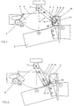
- Fig. 1 is a three-position circuit breaker with one of two arranged in parallel Contact blades 1 (also Fig. 4) made of copper actuable switch contact, a fixed contact 2 and a quenching coil 3 shown.
- the contact blades 1 forming the switching contact are arranged pivotable about a pivot axis S and via a connecting rod 4 and a with a switching shaft 5 rotatably connected crank arm 6 can be actuated together.
- You point each have a shaft 7 and a contact surface 8 corresponding to the fixed contact 2 on, like two opposite contact surfaces 9 of the fixed contact 2, in one Level is formed perpendicular to the pivot axis S.
- Fig. 4 shows that this on one opposite the shaft 7 is formed considerably thicker contact head 10.
- the contact head thickness is about one and a half to two times the thickness of the shaft.
- the contact head 10 is made made of copper and has a tip 11 made of a high temperature resistant tungsten-copper impregnating alloy with 30% copper, which is caused by an arc that forms when switching is subjected to high thermal stress.
- the contact head 10 On the fixed contact side, the contact head 10 is spherical and is pressed by a spring force F against the fixed contact 2.
- This consists of Copper and has in the area corresponding to the tip 11 of the contact head 10 also a tip 12 made of the high temperature-resistant tungsten-copper impregnating alloy on. The tip 11 abuts a shock absorber 13.
- the switch is in a movement phase between the switch positions ON and OFF shown.
- a Arc LB is formed, its two base points each on a substantially perpendicular to the arc formed surface 14 and 15 at the respective tip 11 and 12 respectively.
- Fig. 3 shows that in the switch position EARTHED on a ground contact 16 and one Shock absorber 17 adjacent switch contact 1.
- the tip 11 of the visible switch blade 1 corresponds to a region 18 formed on the ground contact.
- 6a and 6b is a contact knife 1 in a side view and in a plan view shown. In the latter there is a longitudinally formed one in the center of the contact head 10 To see gap 19, which serves to divide the current.
- 7a and 7b show more alternative designs of a contact knife 1, which is characterized by the formation of the tungsten-copper tip differentiate.
- Fig. 7a is compared to the previously described embodiment on the front edge of the contact head 10 reduced tip 20 and in Fig. 7b a half-sided Tip 21 can be seen.
Landscapes
- Arc-Extinguishing Devices That Are Switches (AREA)
- Driving Mechanisms And Operating Circuits Of Arc-Extinguishing High-Tension Switches (AREA)
- Contacts (AREA)
- Emergency Protection Circuit Devices (AREA)
- Supply And Distribution Of Alternating Current (AREA)
- Crystals, And After-Treatments Of Crystals (AREA)
- Developing Agents For Electrophotography (AREA)
- Lubricants (AREA)
Abstract
Description
- Fig. 1:
- eine Phase eines Drei-Stellungs-Leistungsschalters mit einer Löschspule in der Schalterstellung EIN,
- Fig. 2:
- eine Bewegungsphase des beweglichen Schaltkontaktes zwischen den Schalterstellungen EIN und AUS,
- Fig. 3:
- die Phase in der Schalterstellung GEERDET,
- Fig. 4:
- eine Sicht aus der AUS-Position auf den in der Schalterstellung EIN befindlichen Schaltkontakt,
- Fig. 5a bis c:
- die Spitze des Schaltkontaktes in unterschiedlichen Positionen zum Festkontakt,
- Fig. 6a und b:
- ein Kontaktmesser in zwei Ansichten und
- Fig. 7a und b:
- weitere Ausführungen eines Kontaktmessers.
- 1
- Kontaktmesser
- 2
- Festkontakt
- 3
- Löschspule
- 4
- Pleuelstange
- 5
- Schaltwelle
- 6
- Kurbelschwinge
- 7
- Schaft
- 8
- Kontaktfläche
- 9
- Kontaktfläche
- 10
- Kontaktkopt
- 11
- Spitze
- 12
- Spitze
- 13
- Stoßdämpfer
- 14
- Fläche
- 15
- Fläche
- 16
- Erdungskontakt
- 17
- Stoßdämpfer
- 18
- Bereich
- 19
- Spalt
- 20
- Spitze
- 21
- Spitze
- LB
- Lichtbogen
- S
- Schwenkachse
Claims (7)
- Schalter für den Einsatz in SF6-Mittelspannungsschaltanlagen, gebildet aus einem betätigbaren Schaltkontakt mit wenigstens einem Kontaktmesser (1), einem Festkontakt und einer Lichtbogenlöscheinrichtung, wobei das Kontaktmesser (1) einen schwenkbar gelagerten Schaft (7) und eine in einer Ebene im wesentlichen senkrecht zur Schwenkachse (S) ausgebildete Kontaktfläche (8) für den Festkontakt aufweist, dadurch gekennzeichnet, daß die Kontaktfläche (8) an einem gegenüber dem Schaft (7) erheblich dickeren Kontaktkopf (10) ausgebildet ist, und daß der Kontaktkopf (10) in dem durch einen sich beim Schalten ausbildenden Lichtbogen (LB) thermisch beaufschlagten Teil (Spitzen 11, 20, 21) aus einem hochtemperaturbeständigen Werkstoff besteht.
- Schalter nach Anspruch 1, dadurch gekennzeichnet, daß der Festkontakt (2) in dem durch den Lichtbogen (LB) thermisch beaufschlagten Teil (Spitze 12) aus einem hochtemperaturbeständigen Werkstoff besteht.
- Schalter nach Anspruch 1 oder 2, dadurch gekennzeichnet, daß der hochtemperaturbeständige Werkstoff eine Wolfram-Kupfer-Tränklegierung mit 30 % Kupfer ist.
- Schalter nach Anspruch 1, dadurch gekennzeichnet daß der Kontaktkopf (10) festkontaktseitig ballig ausgebildet ist.
- Schalter nach Anspruch 1, dadurch gekennzeichnet, daß das Kontaktmesser (1) in Längsrichtung wenigstens im Bereich des Kontaktkopfes (10) mittig geschlitzt ist (Spalt 19).
- Schalter nach Anspruch 1 oder 2, dadurch gekennzeichnet, daß der aus dem hochtemperaturbeständigen Werkstoff bestehende Teil (Spitze 11, 12, 20, 21) so gestaltet ist, daß dieser eine im wesentlichen senkrecht zum Lichtbogen (LB) ausgebildete Fläche (14, 15) für den jeweiligen Fußpunkt des Lichtbogens (LB) aufweist.
- Schalter nach einem oder mehreren der vorhergehenden Ansprüche, dadurch gekennzeichnet, daß in den definierten Endstellungen (EIN, GEERDET) des Schaltkontaktes Stoßdämpfer (13, 17) für den Kontaktkopf (10) angeordnet sind.
Applications Claiming Priority (2)
| Application Number | Priority Date | Filing Date | Title |
|---|---|---|---|
| DE19904930A DE19904930C2 (de) | 1999-02-06 | 1999-02-06 | Schalter für den Einsatz in SF6-Mittelspannungsschaltanlagen |
| DE19904930 | 1999-02-06 |
Publications (3)
| Publication Number | Publication Date |
|---|---|
| EP1026710A2 true EP1026710A2 (de) | 2000-08-09 |
| EP1026710A3 EP1026710A3 (de) | 2001-11-14 |
| EP1026710B1 EP1026710B1 (de) | 2006-04-12 |
Family
ID=7896691
Family Applications (1)
| Application Number | Title | Priority Date | Filing Date |
|---|---|---|---|
| EP00101480A Expired - Lifetime EP1026710B1 (de) | 1999-02-06 | 2000-01-26 | Schalter für den Einsatz in SF6-Mittelspannungsschaltanlagen |
Country Status (6)
| Country | Link |
|---|---|
| EP (1) | EP1026710B1 (de) |
| AT (1) | ATE323319T1 (de) |
| DE (2) | DE19904930C2 (de) |
| ES (1) | ES2261110T3 (de) |
| NO (1) | NO319046B1 (de) |
| PT (1) | PT1026710E (de) |
Cited By (7)
| Publication number | Priority date | Publication date | Assignee | Title |
|---|---|---|---|---|
| CN101882508A (zh) * | 2009-05-04 | 2010-11-10 | Abb技术股份公司 | 中压线路开关触头装置及包括该触头装置的中压线路开关 |
| EP2565890A1 (de) | 2011-09-01 | 2013-03-06 | Socomec S.A. | Elektrisches Stromunterbrechungsgerät mit hoher Verschlusskraft |
| US8723627B2 (en) | 2011-09-01 | 2014-05-13 | Socomec, S.A. | Electrical cut-off device with high electrodynamic resistance |
| EP2822013A1 (de) * | 2013-07-05 | 2015-01-07 | ABB Technology AG | Hochspannungsleistungsschalter mit Hochspannungs-Schalteinheit |
| US8993908B2 (en) | 2011-09-01 | 2015-03-31 | Socomec S.A. | Moving contact-carrying carriage and electrical cut-off device equipped with such carriage |
| WO2019058631A1 (ja) * | 2017-09-21 | 2019-03-28 | 三菱電機株式会社 | 開閉器 |
| JP6548858B1 (ja) * | 2018-05-10 | 2019-07-24 | 三菱電機株式会社 | 開閉器 |
Family Cites Families (10)
| Publication number | Priority date | Publication date | Assignee | Title |
|---|---|---|---|---|
| AT228318B (de) * | 1961-08-09 | 1963-07-10 | Plansee Metallwerk | Kontakte für Hochspannungsschalter |
| AT286423B (de) * | 1969-01-27 | 1970-12-10 | Plansee Metallwerk | Elektrischer Kontakt |
| FR2048151A5 (de) * | 1969-06-02 | 1971-03-19 | Merlin Gerin | |
| US3691335A (en) * | 1971-03-01 | 1972-09-12 | Westinghouse Electric Corp | Knife blade contact assembly with improved contact engagement position retaining means |
| DE2353627C3 (de) * | 1973-10-26 | 1979-03-22 | Felten & Guilleaume Schaltanlagen Gmbh, 4150 Krefeld | Rohrlöscnkammer for Mittelspannungs-Lasttrennschalter |
| DE7429574U (de) * | 1974-09-03 | 1974-12-05 | Bbc Ag | Kontaktstück |
| DE3820489A1 (de) * | 1988-06-16 | 1989-12-21 | Felten & Guilleaume Energie | Gekapselte lasttrennschalteranordnung |
| US5013876A (en) * | 1988-09-12 | 1991-05-07 | S&C Electric Company | Switch contacts with improved fault-closing capability |
| US5021615A (en) * | 1989-09-29 | 1991-06-04 | Cooper Power Systems, Inc. | On/off loadbreak switch |
| DE4040902C2 (de) * | 1990-12-20 | 1996-01-11 | Felten & Guilleaume Energie | Kipprohrlasttrennschalter |
-
1999
- 1999-02-06 DE DE19904930A patent/DE19904930C2/de not_active Expired - Fee Related
-
2000
- 2000-01-26 DE DE50012546T patent/DE50012546D1/de not_active Expired - Lifetime
- 2000-01-26 ES ES00101480T patent/ES2261110T3/es not_active Expired - Lifetime
- 2000-01-26 PT PT00101480T patent/PT1026710E/pt unknown
- 2000-01-26 AT AT00101480T patent/ATE323319T1/de not_active IP Right Cessation
- 2000-01-26 EP EP00101480A patent/EP1026710B1/de not_active Expired - Lifetime
- 2000-02-04 NO NO20000566A patent/NO319046B1/no not_active IP Right Cessation
Cited By (11)
| Publication number | Priority date | Publication date | Assignee | Title |
|---|---|---|---|---|
| CN101882508A (zh) * | 2009-05-04 | 2010-11-10 | Abb技术股份公司 | 中压线路开关触头装置及包括该触头装置的中压线路开关 |
| EP2249359A1 (de) * | 2009-05-04 | 2010-11-10 | ABB Technology AG | Mittelspannungs-Hauptschalterkontaktanordnung |
| EP2565890A1 (de) | 2011-09-01 | 2013-03-06 | Socomec S.A. | Elektrisches Stromunterbrechungsgerät mit hoher Verschlusskraft |
| US8723627B2 (en) | 2011-09-01 | 2014-05-13 | Socomec, S.A. | Electrical cut-off device with high electrodynamic resistance |
| US8859916B2 (en) | 2011-09-01 | 2014-10-14 | Socomec S.A. | Electrical cut-off device with high making capacity |
| US8993908B2 (en) | 2011-09-01 | 2015-03-31 | Socomec S.A. | Moving contact-carrying carriage and electrical cut-off device equipped with such carriage |
| EP2822013A1 (de) * | 2013-07-05 | 2015-01-07 | ABB Technology AG | Hochspannungsleistungsschalter mit Hochspannungs-Schalteinheit |
| WO2019058631A1 (ja) * | 2017-09-21 | 2019-03-28 | 三菱電機株式会社 | 開閉器 |
| JP6548858B1 (ja) * | 2018-05-10 | 2019-07-24 | 三菱電機株式会社 | 開閉器 |
| WO2019215946A1 (ja) * | 2018-05-10 | 2019-11-14 | 三菱電機株式会社 | 開閉器 |
| US11158466B2 (en) | 2018-05-10 | 2021-10-26 | Mitsubishi Electric Corporation | Switch |
Also Published As
| Publication number | Publication date |
|---|---|
| ES2261110T3 (es) | 2006-11-16 |
| NO20000566L (no) | 2000-08-07 |
| DE19904930A1 (de) | 2000-08-31 |
| NO319046B1 (no) | 2005-06-06 |
| DE50012546D1 (de) | 2006-05-24 |
| DE19904930C2 (de) | 2000-12-14 |
| EP1026710A3 (de) | 2001-11-14 |
| ATE323319T1 (de) | 2006-04-15 |
| EP1026710B1 (de) | 2006-04-12 |
| NO20000566D0 (no) | 2000-02-04 |
| PT1026710E (pt) | 2006-07-31 |
Similar Documents
| Publication | Publication Date | Title |
|---|---|---|
| EP0150486B1 (de) | Elektrischer Schalter | |
| DE19904930C2 (de) | Schalter für den Einsatz in SF6-Mittelspannungsschaltanlagen | |
| EP0951038B1 (de) | Abbrandschaltanordnung | |
| EP1032942B1 (de) | Schaltgerät mit lichtbogen-löscheinrichtung | |
| DE4243314C2 (de) | Strombegrenzender Schalter | |
| EP1095389B1 (de) | Stromkontaktanordnungen eines stromschalters | |
| EP0988638B1 (de) | Abbrandschaltanordnung | |
| EP0360368B1 (de) | Hebel-Druckkontaktanordnung für einen Niederspannungs-Leistungsschalter mit Haupkontaktstücken und Abbrennkontaktstücken | |
| DE948707C (de) | Stromunterbrechungseinrichtung, insbesondere fuer hohe Betriebsspannungen | |
| DE69508680T2 (de) | Hochspannungsschalter | |
| DE69215095T2 (de) | Trennschalter mit Schnappausschaltung | |
| DE3235353C2 (de) | ||
| EP0981147A2 (de) | Leistungsschalter | |
| DE1130495B (de) | Vereisungssicherer Lasttrennschalter | |
| DE19949493A1 (de) | Erdungsschalter | |
| DE4040902C2 (de) | Kipprohrlasttrennschalter | |
| DE2843482C2 (de) | ||
| EP0358288B1 (de) | Kontaktanordnung für einen Leistungsschalter mit Vor- und Hauptkontakten | |
| DE1640007A1 (de) | Kontaktsuecke fuer elektrische Niederspannungs-Wechselstromschalter | |
| EP0168568B1 (de) | Trennschalter, insbesondere Einsäulen-Scherentrennschalter | |
| DE3412449C2 (de) | ||
| DE690847C (de) | Schmelzsicherung mit Haupt- und Nebenschmelzleiter | |
| DE1119960B (de) | Elektrischer Schalter mit getrennten Abreiss- und Hauptkontakten | |
| EP0072771A1 (de) | Ein- oder mehrpoliger Schalter für gekapselte, druckgasisolierte Hochspannungsschaltanlagen | |
| DE3526709A1 (de) | Ein- oder mehrpoliger schalter fuer gekapselte, druckgasisolierte hochspannungsschaltanlagen |
Legal Events
| Date | Code | Title | Description |
|---|---|---|---|
| PUAI | Public reference made under article 153(3) epc to a published international application that has entered the european phase |
Free format text: ORIGINAL CODE: 0009012 |
|
| AK | Designated contracting states |
Kind code of ref document: A2 Designated state(s): AT BE CH CY DE DK ES FI FR GB GR IE IT LI LU MC NL PT SE |
|
| AX | Request for extension of the european patent |
Free format text: AL;LT;LV;MK;RO;SI |
|
| PUAL | Search report despatched |
Free format text: ORIGINAL CODE: 0009013 |
|
| AK | Designated contracting states |
Kind code of ref document: A3 Designated state(s): AT BE CH CY DE DK ES FI FR GB GR IE IT LI LU MC NL PT SE |
|
| AX | Request for extension of the european patent |
Free format text: AL;LT;LV;MK;RO;SI |
|
| 17P | Request for examination filed |
Effective date: 20011005 |
|
| AKX | Designation fees paid |
Free format text: AT BE CH CY DE DK ES FI FR GB GR IE IT LI LU MC NL PT SE |
|
| RAP1 | Party data changed (applicant data changed or rights of an application transferred) |
Owner name: ORMAZABAL ANLAGENTECHNIK GMBH |
|
| GRAP | Despatch of communication of intention to grant a patent |
Free format text: ORIGINAL CODE: EPIDOSNIGR1 |
|
| GRAS | Grant fee paid |
Free format text: ORIGINAL CODE: EPIDOSNIGR3 |
|
| GRAA | (expected) grant |
Free format text: ORIGINAL CODE: 0009210 |
|
| AK | Designated contracting states |
Kind code of ref document: B1 Designated state(s): AT BE CH CY DE DK ES FI FR GB GR IE IT LI LU MC NL PT SE |
|
| PG25 | Lapsed in a contracting state [announced via postgrant information from national office to epo] |
Ref country code: IT Free format text: LAPSE BECAUSE OF FAILURE TO SUBMIT A TRANSLATION OF THE DESCRIPTION OR TO PAY THE FEE WITHIN THE PRESCRIBED TIME-LIMIT;WARNING: LAPSES OF ITALIAN PATENTS WITH EFFECTIVE DATE BEFORE 2007 MAY HAVE OCCURRED AT ANY TIME BEFORE 2007. THE CORRECT EFFECTIVE DATE MAY BE DIFFERENT FROM THE ONE RECORDED. Effective date: 20060412 Ref country code: FI Free format text: LAPSE BECAUSE OF FAILURE TO SUBMIT A TRANSLATION OF THE DESCRIPTION OR TO PAY THE FEE WITHIN THE PRESCRIBED TIME-LIMIT Effective date: 20060412 Ref country code: IE Free format text: LAPSE BECAUSE OF FAILURE TO SUBMIT A TRANSLATION OF THE DESCRIPTION OR TO PAY THE FEE WITHIN THE PRESCRIBED TIME-LIMIT Effective date: 20060412 |
|
| REG | Reference to a national code |
Ref country code: GB Ref legal event code: FG4D Free format text: NOT ENGLISH |
|
| REG | Reference to a national code |
Ref country code: CH Ref legal event code: EP |
|
| REF | Corresponds to: |
Ref document number: 50012546 Country of ref document: DE Date of ref document: 20060524 Kind code of ref document: P |
|
| GBT | Gb: translation of ep patent filed (gb section 77(6)(a)/1977) |
Effective date: 20060508 |
|
| REG | Reference to a national code |
Ref country code: IE Ref legal event code: FG4D Free format text: LANGUAGE OF EP DOCUMENT: GERMAN |
|
| REG | Reference to a national code |
Ref country code: SE Ref legal event code: TRGR |
|
| PG25 | Lapsed in a contracting state [announced via postgrant information from national office to epo] |
Ref country code: DK Free format text: LAPSE BECAUSE OF FAILURE TO SUBMIT A TRANSLATION OF THE DESCRIPTION OR TO PAY THE FEE WITHIN THE PRESCRIBED TIME-LIMIT Effective date: 20060712 |
|
| REG | Reference to a national code |
Ref country code: PT Ref legal event code: SC4A Effective date: 20060522 |
|
| ET | Fr: translation filed | ||
| REG | Reference to a national code |
Ref country code: IE Ref legal event code: FD4D |
|
| REG | Reference to a national code |
Ref country code: ES Ref legal event code: FG2A Ref document number: 2261110 Country of ref document: ES Kind code of ref document: T3 |
|
| PG25 | Lapsed in a contracting state [announced via postgrant information from national office to epo] |
Ref country code: CH Free format text: LAPSE BECAUSE OF NON-PAYMENT OF DUE FEES Effective date: 20070131 Ref country code: MC Free format text: LAPSE BECAUSE OF NON-PAYMENT OF DUE FEES Effective date: 20070131 Ref country code: LI Free format text: LAPSE BECAUSE OF NON-PAYMENT OF DUE FEES Effective date: 20070131 |
|
| PLBE | No opposition filed within time limit |
Free format text: ORIGINAL CODE: 0009261 |
|
| STAA | Information on the status of an ep patent application or granted ep patent |
Free format text: STATUS: NO OPPOSITION FILED WITHIN TIME LIMIT |
|
| 26N | No opposition filed |
Effective date: 20070115 |
|
| REG | Reference to a national code |
Ref country code: CH Ref legal event code: PL |
|
| BERE | Be: lapsed |
Owner name: ORMAZABAL ANLAGENTECHNIK G.M.B.H. Effective date: 20070131 |
|
| PG25 | Lapsed in a contracting state [announced via postgrant information from national office to epo] |
Ref country code: BE Free format text: LAPSE BECAUSE OF NON-PAYMENT OF DUE FEES Effective date: 20070131 |
|
| PG25 | Lapsed in a contracting state [announced via postgrant information from national office to epo] |
Ref country code: GR Free format text: LAPSE BECAUSE OF FAILURE TO SUBMIT A TRANSLATION OF THE DESCRIPTION OR TO PAY THE FEE WITHIN THE PRESCRIBED TIME-LIMIT Effective date: 20060713 |
|
| PG25 | Lapsed in a contracting state [announced via postgrant information from national office to epo] |
Ref country code: AT Free format text: LAPSE BECAUSE OF NON-PAYMENT OF DUE FEES Effective date: 20070126 |
|
| PG25 | Lapsed in a contracting state [announced via postgrant information from national office to epo] |
Ref country code: CY Free format text: LAPSE BECAUSE OF FAILURE TO SUBMIT A TRANSLATION OF THE DESCRIPTION OR TO PAY THE FEE WITHIN THE PRESCRIBED TIME-LIMIT Effective date: 20060412 Ref country code: LU Free format text: LAPSE BECAUSE OF NON-PAYMENT OF DUE FEES Effective date: 20070126 |
|
| REG | Reference to a national code |
Ref country code: FR Ref legal event code: PLFP Year of fee payment: 16 |
|
| PGFP | Annual fee paid to national office [announced via postgrant information from national office to epo] |
Ref country code: NL Payment date: 20150121 Year of fee payment: 16 |
|
| PGFP | Annual fee paid to national office [announced via postgrant information from national office to epo] |
Ref country code: ES Payment date: 20150129 Year of fee payment: 16 Ref country code: IT Payment date: 20150123 Year of fee payment: 16 |
|
| PGFP | Annual fee paid to national office [announced via postgrant information from national office to epo] |
Ref country code: GB Payment date: 20150121 Year of fee payment: 16 Ref country code: FR Payment date: 20150121 Year of fee payment: 16 |
|
| PGFP | Annual fee paid to national office [announced via postgrant information from national office to epo] |
Ref country code: PT Payment date: 20151216 Year of fee payment: 17 |
|
| GBPC | Gb: european patent ceased through non-payment of renewal fee |
Effective date: 20160126 |
|
| REG | Reference to a national code |
Ref country code: NL Ref legal event code: MM Effective date: 20160201 |
|
| REG | Reference to a national code |
Ref country code: FR Ref legal event code: ST Effective date: 20160930 |
|
| PG25 | Lapsed in a contracting state [announced via postgrant information from national office to epo] |
Ref country code: GB Free format text: LAPSE BECAUSE OF NON-PAYMENT OF DUE FEES Effective date: 20160126 |
|
| PG25 | Lapsed in a contracting state [announced via postgrant information from national office to epo] |
Ref country code: NL Free format text: LAPSE BECAUSE OF NON-PAYMENT OF DUE FEES Effective date: 20160201 Ref country code: FR Free format text: LAPSE BECAUSE OF NON-PAYMENT OF DUE FEES Effective date: 20160201 |
|
| PG25 | Lapsed in a contracting state [announced via postgrant information from national office to epo] |
Ref country code: IT Free format text: LAPSE BECAUSE OF NON-PAYMENT OF DUE FEES Effective date: 20160126 |
|
| REG | Reference to a national code |
Ref country code: ES Ref legal event code: FD2A Effective date: 20170224 |
|
| PGFP | Annual fee paid to national office [announced via postgrant information from national office to epo] |
Ref country code: SE Payment date: 20170124 Year of fee payment: 18 Ref country code: DE Payment date: 20170124 Year of fee payment: 18 |
|
| PG25 | Lapsed in a contracting state [announced via postgrant information from national office to epo] |
Ref country code: ES Free format text: LAPSE BECAUSE OF NON-PAYMENT OF DUE FEES Effective date: 20160127 |
|
| PG25 | Lapsed in a contracting state [announced via postgrant information from national office to epo] |
Ref country code: PT Free format text: LAPSE BECAUSE OF NON-PAYMENT OF DUE FEES Effective date: 20170726 |
|
| REG | Reference to a national code |
Ref country code: DE Ref legal event code: R119 Ref document number: 50012546 Country of ref document: DE |
|
| REG | Reference to a national code |
Ref country code: SE Ref legal event code: EUG |
|
| PG25 | Lapsed in a contracting state [announced via postgrant information from national office to epo] |
Ref country code: SE Free format text: LAPSE BECAUSE OF NON-PAYMENT OF DUE FEES Effective date: 20180127 Ref country code: DE Free format text: LAPSE BECAUSE OF NON-PAYMENT OF DUE FEES Effective date: 20180801 |