EP1027201B1 - Procede et appareil de moulage pour brosses a dents - Google Patents
Procede et appareil de moulage pour brosses a dents Download PDFInfo
- Publication number
- EP1027201B1 EP1027201B1 EP98958879A EP98958879A EP1027201B1 EP 1027201 B1 EP1027201 B1 EP 1027201B1 EP 98958879 A EP98958879 A EP 98958879A EP 98958879 A EP98958879 A EP 98958879A EP 1027201 B1 EP1027201 B1 EP 1027201B1
- Authority
- EP
- European Patent Office
- Prior art keywords
- cavity
- pressure
- molding
- injection
- defining
- Prior art date
- Legal status (The legal status is an assumption and is not a legal conclusion. Google has not performed a legal analysis and makes no representation as to the accuracy of the status listed.)
- Expired - Lifetime
Links
- 238000000034 method Methods 0.000 title claims abstract description 17
- 238000000465 moulding Methods 0.000 title claims abstract description 15
- 239000012778 molding material Substances 0.000 claims abstract description 24
- 238000002347 injection Methods 0.000 claims abstract description 23
- 239000007924 injection Substances 0.000 claims abstract description 23
- 239000000835 fiber Substances 0.000 claims abstract description 10
- 230000035515 penetration Effects 0.000 claims abstract description 6
- 239000000463 material Substances 0.000 claims description 4
- 230000000903 blocking effect Effects 0.000 claims description 2
- 238000012544 monitoring process Methods 0.000 claims description 2
- 238000004519 manufacturing process Methods 0.000 description 1
- 239000012768 molten material Substances 0.000 description 1
- 239000008188 pellet Substances 0.000 description 1
- 230000011664 signaling Effects 0.000 description 1
- 238000007669 thermal treatment Methods 0.000 description 1
- 238000009757 thermoplastic moulding Methods 0.000 description 1
Images

Classifications
-
- B—PERFORMING OPERATIONS; TRANSPORTING
- B29—WORKING OF PLASTICS; WORKING OF SUBSTANCES IN A PLASTIC STATE IN GENERAL
- B29C—SHAPING OR JOINING OF PLASTICS; SHAPING OF MATERIAL IN A PLASTIC STATE, NOT OTHERWISE PROVIDED FOR; AFTER-TREATMENT OF THE SHAPED PRODUCTS, e.g. REPAIRING
- B29C45/00—Injection moulding, i.e. forcing the required volume of moulding material through a nozzle into a closed mould; Apparatus therefor
- B29C45/17—Component parts, details or accessories; Auxiliary operations
- B29C45/76—Measuring, controlling or regulating
- B29C45/7613—Measuring, controlling or regulating the termination of flow of material into the mould
-
- B—PERFORMING OPERATIONS; TRANSPORTING
- B29—WORKING OF PLASTICS; WORKING OF SUBSTANCES IN A PLASTIC STATE IN GENERAL
- B29C—SHAPING OR JOINING OF PLASTICS; SHAPING OF MATERIAL IN A PLASTIC STATE, NOT OTHERWISE PROVIDED FOR; AFTER-TREATMENT OF THE SHAPED PRODUCTS, e.g. REPAIRING
- B29C45/00—Injection moulding, i.e. forcing the required volume of moulding material through a nozzle into a closed mould; Apparatus therefor
- B29C45/14—Injection moulding, i.e. forcing the required volume of moulding material through a nozzle into a closed mould; Apparatus therefor incorporating preformed parts or layers, e.g. injection moulding around inserts or for coating articles
- B29C45/14336—Coating a portion of the article, e.g. the edge of the article
- B29C45/14385—Coating a portion of a bundle of inserts, e.g. making brushes
- B29C2045/14393—Coating a portion of a bundle of inserts, e.g. making brushes preventing leakage of injected material into tuft insertion holes of the mould
-
- B—PERFORMING OPERATIONS; TRANSPORTING
- B29—WORKING OF PLASTICS; WORKING OF SUBSTANCES IN A PLASTIC STATE IN GENERAL
- B29C—SHAPING OR JOINING OF PLASTICS; SHAPING OF MATERIAL IN A PLASTIC STATE, NOT OTHERWISE PROVIDED FOR; AFTER-TREATMENT OF THE SHAPED PRODUCTS, e.g. REPAIRING
- B29C2945/00—Indexing scheme relating to injection moulding, i.e. forcing the required volume of moulding material through a nozzle into a closed mould
- B29C2945/76—Measuring, controlling or regulating
- B29C2945/76003—Measured parameter
- B29C2945/76006—Pressure
-
- B—PERFORMING OPERATIONS; TRANSPORTING
- B29—WORKING OF PLASTICS; WORKING OF SUBSTANCES IN A PLASTIC STATE IN GENERAL
- B29C—SHAPING OR JOINING OF PLASTICS; SHAPING OF MATERIAL IN A PLASTIC STATE, NOT OTHERWISE PROVIDED FOR; AFTER-TREATMENT OF THE SHAPED PRODUCTS, e.g. REPAIRING
- B29C2945/00—Indexing scheme relating to injection moulding, i.e. forcing the required volume of moulding material through a nozzle into a closed mould
- B29C2945/76—Measuring, controlling or regulating
- B29C2945/76177—Location of measurement
- B29C2945/76254—Mould
- B29C2945/76257—Mould cavity
-
- B—PERFORMING OPERATIONS; TRANSPORTING
- B29—WORKING OF PLASTICS; WORKING OF SUBSTANCES IN A PLASTIC STATE IN GENERAL
- B29C—SHAPING OR JOINING OF PLASTICS; SHAPING OF MATERIAL IN A PLASTIC STATE, NOT OTHERWISE PROVIDED FOR; AFTER-TREATMENT OF THE SHAPED PRODUCTS, e.g. REPAIRING
- B29C2945/00—Indexing scheme relating to injection moulding, i.e. forcing the required volume of moulding material through a nozzle into a closed mould
- B29C2945/76—Measuring, controlling or regulating
- B29C2945/76451—Measurement means
- B29C2945/76478—Mechanical
-
- B—PERFORMING OPERATIONS; TRANSPORTING
- B29—WORKING OF PLASTICS; WORKING OF SUBSTANCES IN A PLASTIC STATE IN GENERAL
- B29C—SHAPING OR JOINING OF PLASTICS; SHAPING OF MATERIAL IN A PLASTIC STATE, NOT OTHERWISE PROVIDED FOR; AFTER-TREATMENT OF THE SHAPED PRODUCTS, e.g. REPAIRING
- B29C2945/00—Indexing scheme relating to injection moulding, i.e. forcing the required volume of moulding material through a nozzle into a closed mould
- B29C2945/76—Measuring, controlling or regulating
- B29C2945/76451—Measurement means
- B29C2945/76488—Magnetic, electro-magnetic
-
- B—PERFORMING OPERATIONS; TRANSPORTING
- B29—WORKING OF PLASTICS; WORKING OF SUBSTANCES IN A PLASTIC STATE IN GENERAL
- B29C—SHAPING OR JOINING OF PLASTICS; SHAPING OF MATERIAL IN A PLASTIC STATE, NOT OTHERWISE PROVIDED FOR; AFTER-TREATMENT OF THE SHAPED PRODUCTS, e.g. REPAIRING
- B29C2945/00—Indexing scheme relating to injection moulding, i.e. forcing the required volume of moulding material through a nozzle into a closed mould
- B29C2945/76—Measuring, controlling or regulating
- B29C2945/76494—Controlled parameter
- B29C2945/76531—Temperature
-
- B—PERFORMING OPERATIONS; TRANSPORTING
- B29—WORKING OF PLASTICS; WORKING OF SUBSTANCES IN A PLASTIC STATE IN GENERAL
- B29C—SHAPING OR JOINING OF PLASTICS; SHAPING OF MATERIAL IN A PLASTIC STATE, NOT OTHERWISE PROVIDED FOR; AFTER-TREATMENT OF THE SHAPED PRODUCTS, e.g. REPAIRING
- B29C2945/00—Indexing scheme relating to injection moulding, i.e. forcing the required volume of moulding material through a nozzle into a closed mould
- B29C2945/76—Measuring, controlling or regulating
- B29C2945/76494—Controlled parameter
- B29C2945/76551—Time
- B29C2945/76558—Time termination
-
- B—PERFORMING OPERATIONS; TRANSPORTING
- B29—WORKING OF PLASTICS; WORKING OF SUBSTANCES IN A PLASTIC STATE IN GENERAL
- B29C—SHAPING OR JOINING OF PLASTICS; SHAPING OF MATERIAL IN A PLASTIC STATE, NOT OTHERWISE PROVIDED FOR; AFTER-TREATMENT OF THE SHAPED PRODUCTS, e.g. REPAIRING
- B29C2945/00—Indexing scheme relating to injection moulding, i.e. forcing the required volume of moulding material through a nozzle into a closed mould
- B29C2945/76—Measuring, controlling or regulating
- B29C2945/76655—Location of control
- B29C2945/76775—Fluids
- B29C2945/76785—Fluids hydraulic fluids
-
- B—PERFORMING OPERATIONS; TRANSPORTING
- B29—WORKING OF PLASTICS; WORKING OF SUBSTANCES IN A PLASTIC STATE IN GENERAL
- B29C—SHAPING OR JOINING OF PLASTICS; SHAPING OF MATERIAL IN A PLASTIC STATE, NOT OTHERWISE PROVIDED FOR; AFTER-TREATMENT OF THE SHAPED PRODUCTS, e.g. REPAIRING
- B29C2945/00—Indexing scheme relating to injection moulding, i.e. forcing the required volume of moulding material through a nozzle into a closed mould
- B29C2945/76—Measuring, controlling or regulating
- B29C2945/76929—Controlling method
- B29C2945/76939—Using stored or historical data sets
- B29C2945/76943—Using stored or historical data sets compare with thresholds
Definitions
- the present invention relates to a method of molding toothbrushes and to an apparatus for performing the method.
- Molding of toothbrushes with tufts of fibre or bristles incorporated in the head portion of the brush body during the injection step involves a specific problem.
- One of the relatively movable mold parts has a brush head defining cavity portion with a plurality of holes for partial penetration into the cavity portion of a like number of fibre tufts. Due to the viscosity of the heated plasticized molding material and to the pressure within the cavity during injection, leakage is likely to occur through the holes in the brush head defining cavity portion. Many attempts have been made to avoid such leakage.
- a mold with relatively movable mold parts defining at least one molding cavity corresponding in shape to a toothbrush body is used.
- One of the mold parts has a brush head defining cavity portion with a plurality of holes for partial penetration into the cavity portion of a like number of fibre tufts.
- the inventive method comprises the steps of providing a supply of plasticized molding material, injecting the plasticized material under pressure into the cavity, sensing and monitoring pressure within the cavity during the injecting step, and stopping injection when the pressure within the cavity exceeds a predetermined pressure value, wherein injection of the molding material is performed from a first longitudinal end of the cavity and pressure is sensed at a second, opposed longitudinal end of the cavity within the brush head defining cavity portion.
- the invention proposes to sense pressure during the injection step in the very cavity, and at one end of the elongate cavity which corresponds to the brush head portion.
- the injection of molding material is performed through a narrow injection channel which opens into the cavity at an end opposite the end where pressure is sensed, and stopping of injection is carried out by suddenly blocking material flow through the channel at a location close to the cavity.
- a plurality of toothbrushes are simultaneously molded in a plurality of cavities and pressure is sensed in each cavity. Stopping of injection in each individual cavity is controlled by pressure sensed in that cavity.
- a mold with a plurality of like cavities is usually provided with a balanced manifold system, identical amounts of pressure in each cavity cannot be achieved due to manufacture tolerances and fluctuations of the molding parameters such as viscosity and temperature.
- the predetermined pressure level at which supply of molding material of the cavities is suddenly stopped must be selected below a value where leakage starts to occur.
- the appropriate pressure level will depend on the nature of the molding material and on the characteristics of the mold. It can be determined empirically.
- the invention is not limited to methods wherein the brush body is molded from a single molding material. Rather, a first molding material can be injected in a first injection step forming a frame brush incorporating the fibre tufts, and at least one further molding material component is injected in a second molding step to complete the toothbrush.
- a precise pressure control as described in this invention may only be needed during the first injection step. However, a second control system may be needed if the second component also imbeds (part of) the tufted portion of the brush or if the second component gets into the vicinity thereof (eg. for brushes featuring second component in the brushhead).
- the invention also provides an apparatus for performing the method.
- the apparatus comprises a mold with relatively movable mold parts defining at least one molding cavity corresponding in shape to a toothbrush body.
- the cavity has a brush head defining cavity portion with a plurality of holes for partial penetration into the cavity portion of a like number of fibre tufts.
- the apparatus further comprises a plasticizing and pressurizing supply unit.
- a narrow supply channel connects the cavity with the supply unit at first longitudinal end of the cavity.
- a pressure sensor is associated with the cavity by means of a pressure sensor line which is connected with the cavity at a second, opposed longitudinal end of the cavity corresponding to the brush head defining cavity portion.
- a valve member adapted to shut off the cavity. supply channel is arranged adjacent the cavity.
- a control unit controls the valve member in dependence upon pressure sensed by the pressure sensor within the brush head defining cavity portion.
- the mold comprises a plurality of like cavities
- the supply unit comprises a manifold with a plurality of supply channels each connected to one of the cavities, and each supply channel has an associated valve member.
- each valve member is controlled individually by the control unit in dependance upon pressure sensed in the associated cavity.
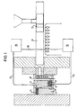
- the apparatus shown in Fig. 1 includes a conventional plasticizing and pressurizing supply unit with a cylinder 10 and a plunger 12 and a mold with a first, stationary mold part 14 and a second, movable mold part 16.
- the cylinder 10 is filled with pellets of a thermoplastic molding material which are plasticized within the cylinder through a combination of mechanical and thermal treatment.
- the mold is connected to cylinder 10 by a manifold system 18.
- Mold parts 14, 16 commonly define a cavity which has the elongate shape of a toothbrush body.
- a narrow supply channel 22 extends from one end of cavity 20 through stationary mold part 14 and is connected to the manifold system 18.
- the movable mold part 16 On the opposite end of cavity 20 which corresponds to the toothbrush head, the movable mold part 16 has a number of holes 24 for the introduction of fibre tufts, the ends of which slightly project into cavity 20.
- a pressure sensing line 26 is connected to the same end of cavity 20. Pressure sensing line 26 is connected to an input of a controller 28.
- a valve member 32 formed as a gate valve with a movable shutter 34 is arranged near the end of supply channel 22 opening into cavity 20 so that the supply channel 22 can be selectively shut off.
- a hydraulic control unit 30 has an input connected to an output of controller 28 by a signalling line 29 and an output connected to valve member 32 by a control line 33.
- plasticized molding material is supplied by the supply unit through manifold 18 and supply channel 22 into cavity 20 after a set of tufts has been introduced through the holes 24 in movable mold part 16.
- the pressure within the cavity is monitored in controller unit 28. More specifically, the pressure is sensed at the end of cavity 20 which corresponds to the brush head, i.e. the location within cavity 20 where pressure is most critical.
- a control signal is sent from the controller unit 28 to the hydraulic control unit 30 which, in turn, controls valve member 32 to suddenly block the flow of molding material towards cavity 20.
- the predetermined pressure value is selected slightly lower than a value where molding material starts leaking through holes 24. The pressure value where leakage of molding material starts to occur depends on the nature of the molding material and other molding parameters, and can be determined emperically.
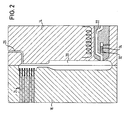
- Fig. 3 is generally similar to that of Fig. 1 and differs only in that a plurality of like mold cavities 20a, 20b are provided which are connected to the common manifold system 18, each through a separate supply channel 22 with an associated valve member 32.
- Each cavity 20a, 20b has its cavity portion corresponding to the brush head connected by an associated pressure sensing line 26 to the control unit 20a.
- the hydraulic control unit 30 is connected to each of the valve members 32.
- two cavities 20a, 20b are shown in Fig. 3, a number of similar cavities can be arranged in two or more rows, in a closely spaced and parallel relationship in each row.
- the pressures in all cavities are monitored during injection, and the valve members of all cavities are individually controlled in dependence of sensed pressure in corresponding cavities.
- the predetermined pressure value can be the same for all cavities if the manifold system 18 is balanced and the temperature control is sufficiently precise throughout the mold. Alternatively, a set of predetermined pressure values can be defined, one for each cavity.
- pressure sensing lines 26 are shown in the drawings, a pressure sensor can be arranged immediately adjacent the mold cavity, and the pressure sensing line may be an electric cable.
- valve members can be controlled by other than hydraulic means, for example mechanical, magnetic or pneumatic.
Landscapes
- Engineering & Computer Science (AREA)
- Manufacturing & Machinery (AREA)
- Mechanical Engineering (AREA)
- Moulds For Moulding Plastics Or The Like (AREA)
- Injection Moulding Of Plastics Or The Like (AREA)
- Brushes (AREA)
Abstract
Claims (9)
- Procédé de moulage de brosses à dents en utilisant un moule possédant des parties de moule (14, 16) mobiles l'une par rapport à l'autre et définissant au moins une cavité de moulage (20) dont la forme correspond à un corps de brosse à dents, une (16) des parties de moule possédant une portion de cavité définissant une tête de brosse et présentant une pluralité de trous (24) pour une pénétration partielle d'un même nombre de touffes de fibres dans la portion de cavité,
comprenant les étapes suivantes :caractérisé par les étapes supplémentaires suivantes :prévoir une alimentation en matière plastifiée de moulage, etinjecter sous pression dans la cavité (20) la matière plastifiée ;détecter et surveiller la pression à l'intérieur de la cavité (20) durant l'étape d'injection,et arrêter l'injection lorsque la pression à l'intérieur de la cavité (20) dépasse une valeur prédéterminée de pression,l'injection de la matière de moulage étant réalisée à une première extrémité longitudinale de la cavité (20) et la pression étant détectée à une deuxième extrémité opposée et longitudinale de la cavité (20) à l'intérieur de la portion de cavité définissant la tête de brosse. - Procédé selon la revendication 1, dans lequel l'injection de la matière de moulage est réalisée à travers un canal (22) étroit d'injection et l'arrêt de l'injection est effectué en bloquant soudainement le flux de matière à travers le canal (22) à un emplacement près de la cavité.
- Procédé selon l'une des revendications 1 à 2, dans lequel la valeur prédéterminée de pression est choisie inférieure à une valeur à laquelle la matière de moulage s'écoule à travers les trous (24) dans la portion définissant la cavité de tête de brosse.
- Procédé selon l'une des revendications 1 à 3, dans lequel une pluralité de brosses à dents sont moulées simultanément dans une pluralité de cavités (20a, 20b) et la pression est détectée dans chaque cavité, et l'arrêt de l'injection dans chaque cavité (20a, 20b) individuelle est commandé par la pression détectée dans cette cavité.
- Procédé selon l'une des revendications 1 à 4, dans lequel un premier composant de matière de moulage est injecté lors d'une première étape d'injection moulant un cadre de brosse qui incorpore les touffes de fibres, et au moins un composant supplémentaire de matière de moulage est injecté lors d'une deuxième étape de moulage pour compléter la brosse à dents.
- Procédé selon la revendication 5, dans lequel la pression est détectée à l'intérieur de la cavité seulement lors de la première étape d'injection.
- Appareil de moulage pour réaliser le procédé selon l'une des revendications précédentes, comportant un moule possédant des parties de moule (14, 16) mobiles l'une par rapport à l'autre et définissant au moins une cavité de moulage (20) dont la forme correspond à un corps de brosse à dents, la cavité (20) possédant une portion de cavité définissant une tête de brosse et présentant une pluralité de trous (24) pour une pénétration partielle d'un même nombre de touffes de fibres dans la portion de cavité, et comprenant en outre une unité d'alimentation (10) pour la plastification et pressurisation, caractérisé par un canal (22) étroit d'alimentation reliant la cavité (20) à l'unité d'alimentation (10) vers une première extrémité longitudinale de la cavité (20), un capteur de pression (28) associé à la cavité (20) par l'intermédiaire d'une conduite (26) de capteur de pression reliée à la cavité (20) vers une deuxième extrémité opposée et longitudinale de la cavité (20) correspondant à la portion définissant la cavité de tête de brosse, un élément de valve (32) adapté à fermer le canal d'alimentation (22) et adjacent à la cavité (20), et une unité de commande (30) commandant l'élément de valve (32) en fonction d'une pression détectée par le capteur de pression (28) à l'intérieur de la portion de cavité définissant la tête de brosse.
- Appareil selon la revendication 7, dans lequel le moule comporte une pluralité de cavités (20a, 20b) semblables et l'unité d'alimentation (10) comporte un distributeur (18), une pluralité de canaux d'alimentation (22) étant respectivement reliés à une des cavités et chaque canal d'alimentation (22) ayant un élément de valve associé (32).
- Appareil selon la revendication 8, dans lequel chacun des éléments de valve (32) est individuellement commandé par l'unité de commande (30) en fonction de la pression détectée dans la cavité (20a, 20b) associée.
Applications Claiming Priority (3)
| Application Number | Priority Date | Filing Date | Title |
|---|---|---|---|
| GB9722946 | 1997-10-30 | ||
| GB9722946A GB2330791B (en) | 1997-10-30 | 1997-10-30 | Method of molding toothbrushes and apparatus for performing the method |
| PCT/EP1998/006855 WO1999022925A1 (fr) | 1997-10-30 | 1998-10-29 | Procede et appareil de moulage pour brosses a dents |
Publications (2)
| Publication Number | Publication Date |
|---|---|
| EP1027201A1 EP1027201A1 (fr) | 2000-08-16 |
| EP1027201B1 true EP1027201B1 (fr) | 2004-11-17 |
Family
ID=10821329
Family Applications (1)
| Application Number | Title | Priority Date | Filing Date |
|---|---|---|---|
| EP98958879A Expired - Lifetime EP1027201B1 (fr) | 1997-10-30 | 1998-10-29 | Procede et appareil de moulage pour brosses a dents |
Country Status (22)
| Country | Link |
|---|---|
| US (1) | US6451229B1 (fr) |
| EP (1) | EP1027201B1 (fr) |
| JP (1) | JP2001521836A (fr) |
| KR (1) | KR20010031454A (fr) |
| CN (1) | CN1123434C (fr) |
| AP (1) | AP2000001799A0 (fr) |
| AT (1) | ATE282515T1 (fr) |
| AU (1) | AU737410B2 (fr) |
| BG (1) | BG104375A (fr) |
| BR (1) | BR9813330A (fr) |
| CA (1) | CA2307804A1 (fr) |
| DE (1) | DE69827660T2 (fr) |
| GB (1) | GB2330791B (fr) |
| HU (1) | HUP0004859A3 (fr) |
| IL (1) | IL135882A (fr) |
| NO (1) | NO20002229L (fr) |
| NZ (1) | NZ504380A (fr) |
| PL (1) | PL340240A1 (fr) |
| RU (1) | RU2206453C2 (fr) |
| UA (1) | UA57612C2 (fr) |
| WO (1) | WO1999022925A1 (fr) |
| YU (1) | YU24600A (fr) |
Families Citing this family (9)
| Publication number | Priority date | Publication date | Assignee | Title |
|---|---|---|---|---|
| US6372162B1 (en) | 1999-08-31 | 2002-04-16 | The Gillette Company | Injection molding of oral brush bodies |
| US6578929B2 (en) * | 2001-05-23 | 2003-06-17 | The Gillette Company | Tufting oral brushes |
| US20030116884A1 (en) * | 2001-12-21 | 2003-06-26 | Wagstaff Robert K. | Method for making a tongue cleaning device |
| DE10221869A1 (de) * | 2002-05-15 | 2003-11-27 | Coronet Werke Gmbh | Verfahren zur Herstellung einer Borstenstruktur an einem Träger |
| US20040177462A1 (en) | 2003-03-14 | 2004-09-16 | The Gillette Company | Toothbrush head |
| US20060272112A9 (en) | 2003-03-14 | 2006-12-07 | The Gillette Company | Toothbrush |
| US8056176B2 (en) | 2007-01-25 | 2011-11-15 | The Procter & Gamble Company | Toothbrushes |
| DE102019115097A1 (de) * | 2019-06-05 | 2020-12-10 | Cqlt Saargummi Technologies S.À.R.L. | Spritzgusswerkzeug |
| WO2023114049A1 (fr) * | 2021-12-13 | 2023-06-22 | Barnes Group Inc. | Dispositif et méthode de moulage par injection |
Family Cites Families (18)
| Publication number | Priority date | Publication date | Assignee | Title |
|---|---|---|---|---|
| GB917522A (en) * | 1958-05-17 | 1963-02-06 | British United Shoe Machinery | Improvements in or relating to injection moulding machines |
| JPS5574849A (en) * | 1978-11-30 | 1980-06-05 | Matsushita Electric Works Ltd | Metallic mold |
| US4490315A (en) * | 1982-02-04 | 1984-12-25 | Northern Telecom Limited | Methods of moulding of plastics articles |
| GB8326926D0 (en) * | 1983-10-07 | 1983-11-09 | Harper A R | Injecting liquid resin |
| DE3512192A1 (de) * | 1985-04-03 | 1986-10-09 | Wolfgang 6149 Rimbach Bickel | Verfahren, maschinen und werkzeuge zum herstellen von buersten, besen und dgl. |
| AT390029B (de) * | 1987-09-29 | 1990-03-12 | Engel Gmbh Maschbau | Spritzgiessmaschine |
| SU1548066A1 (ru) * | 1988-05-20 | 1990-03-07 | Предприятие П/Я В-8729 | Автоматическа литьева форма дл лить под давлением длинноворсовой монолитной пластмассовой щетки |
| ES2071703T3 (es) * | 1990-06-28 | 1995-07-01 | Boucherie Nv G B | Maquina para fabricar cepillos. |
| DE4034811C2 (de) * | 1990-11-02 | 2003-08-21 | Zahoransky Anton Gmbh & Co | Bürstenherstellungsmaschine |
| GB2288140A (en) * | 1994-04-07 | 1995-10-11 | Boucherie Nv G B | A method of injection molding of brushes |
| GB2288564B (en) * | 1994-04-19 | 1998-09-23 | Boucherie Nv G B | A molding machine for injection molding of tooth brushes |
| US5766526B1 (en) * | 1994-04-20 | 1999-08-24 | Fuji Photo Film Co Ltd | Method and apparatus for injection molding |
| GB9408595D0 (en) * | 1994-04-29 | 1994-06-22 | Body Shop Int Plc | An exfoliating product |
| US5447425A (en) * | 1994-08-11 | 1995-09-05 | Leopardex Industrial Co., Ltd. | Injection molding assembly for forming foam products |
| DE19513451A1 (de) * | 1995-04-08 | 1996-10-10 | Zahoransky Anton Gmbh & Co | Verfahren zum Herstellen von Bürsten |
| WO1998000279A1 (fr) | 1996-06-27 | 1998-01-08 | Georg Kaufmann | Procede et dispositif pour produire des elements mobiles d'une piece en plastique |
| US6123535A (en) | 1996-08-02 | 2000-09-26 | Libbey-Owens-Ford Co. | Molding apparatus for encapsulating a part |
| IT1287126B1 (it) | 1996-10-31 | 1998-08-04 | Tetra Laval Holdings & Finance | Procedimento e utensili a stampo per lo stampaggio ad iniezione di una parte di materia plastica in un materiale in foglio da imballaggio |
-
1997
- 1997-10-30 GB GB9722946A patent/GB2330791B/en not_active Expired - Fee Related
-
1998
- 1998-10-29 UA UA2000042503A patent/UA57612C2/uk unknown
- 1998-10-29 AT AT98958879T patent/ATE282515T1/de not_active IP Right Cessation
- 1998-10-29 HU HU0004859A patent/HUP0004859A3/hu unknown
- 1998-10-29 JP JP2000518829A patent/JP2001521836A/ja active Pending
- 1998-10-29 CN CN98810858A patent/CN1123434C/zh not_active Expired - Fee Related
- 1998-10-29 IL IL13588298A patent/IL135882A/xx not_active IP Right Cessation
- 1998-10-29 BR BR9813330-6A patent/BR9813330A/pt active Search and Examination
- 1998-10-29 AP APAP/P/2000/001799A patent/AP2000001799A0/en unknown
- 1998-10-29 PL PL98340240A patent/PL340240A1/xx unknown
- 1998-10-29 KR KR1020007004487A patent/KR20010031454A/ko not_active Ceased
- 1998-10-29 NZ NZ504380A patent/NZ504380A/en unknown
- 1998-10-29 CA CA002307804A patent/CA2307804A1/fr not_active Abandoned
- 1998-10-29 AU AU14868/99A patent/AU737410B2/en not_active Ceased
- 1998-10-29 WO PCT/EP1998/006855 patent/WO1999022925A1/fr not_active Ceased
- 1998-10-29 DE DE69827660T patent/DE69827660T2/de not_active Expired - Lifetime
- 1998-10-29 RU RU2000113726/12A patent/RU2206453C2/ru not_active IP Right Cessation
- 1998-10-29 EP EP98958879A patent/EP1027201B1/fr not_active Expired - Lifetime
- 1998-10-29 US US09/530,266 patent/US6451229B1/en not_active Expired - Fee Related
- 1998-10-29 YU YU24600A patent/YU24600A/sh unknown
-
2000
- 2000-04-25 BG BG104375A patent/BG104375A/xx unknown
- 2000-04-28 NO NO20002229A patent/NO20002229L/no not_active Application Discontinuation
Also Published As
| Publication number | Publication date |
|---|---|
| UA57612C2 (uk) | 2003-06-16 |
| BR9813330A (pt) | 2000-08-22 |
| IL135882A0 (en) | 2001-05-20 |
| DE69827660T2 (de) | 2005-12-01 |
| US6451229B1 (en) | 2002-09-17 |
| GB9722946D0 (en) | 1998-01-07 |
| RU2206453C2 (ru) | 2003-06-20 |
| GB2330791A (en) | 1999-05-05 |
| WO1999022925A1 (fr) | 1999-05-14 |
| PL340240A1 (en) | 2001-01-29 |
| CA2307804A1 (fr) | 1999-05-14 |
| GB2330791B (en) | 2002-05-08 |
| CN1123434C (zh) | 2003-10-08 |
| NZ504380A (en) | 2002-05-31 |
| KR20010031454A (ko) | 2001-04-16 |
| AU737410B2 (en) | 2001-08-16 |
| IL135882A (en) | 2003-11-23 |
| ATE282515T1 (de) | 2004-12-15 |
| AU1486899A (en) | 1999-05-24 |
| DE69827660D1 (de) | 2004-12-23 |
| BG104375A (en) | 2000-11-30 |
| YU24600A (sh) | 2001-09-28 |
| EP1027201A1 (fr) | 2000-08-16 |
| NO20002229D0 (no) | 2000-04-28 |
| AP2000001799A0 (en) | 2000-06-30 |
| HUP0004859A3 (en) | 2002-01-28 |
| JP2001521836A (ja) | 2001-11-13 |
| CN1278206A (zh) | 2000-12-27 |
| NO20002229L (no) | 2000-06-29 |
| HUP0004859A2 (hu) | 2001-04-28 |
Similar Documents
| Publication | Publication Date | Title |
|---|---|---|
| EP1027201B1 (fr) | Procede et appareil de moulage pour brosses a dents | |
| US7431871B2 (en) | Method for regulating the contraction of molded parts | |
| JP4410317B2 (ja) | 合成樹脂製射出成形品の製造方法および装置 | |
| US5260012A (en) | Molding plastic articles | |
| EP0743159B1 (fr) | Machine à mouler par injection à entrée d'injection latérale avec inserts d'entrée d'injection montés radialement | |
| EP1406754A1 (fr) | Procede et dispositif pour le moulage d'articles par injection | |
| RU2000113726A (ru) | Способ формования зубных щеток и устройство для осуществления этого способа | |
| JP2631064B2 (ja) | フローモールド成形方法 | |
| EP0764510A2 (fr) | Procédé de moulage par injection assisté par gaz et dispositif | |
| CA2528105A1 (fr) | Procede et dispositif d'injection d'une piece en plastique moulee par injection | |
| CZ294486B6 (cs) | Zařízení pro tvarování vstřikováním | |
| CZ20001589A3 (cs) | Způsob tvarování zubních kartáčků a zařízení k provádění způsobu | |
| JP2002355869A (ja) | レンズの多数個取り射出圧縮成形方法 | |
| JP3336268B2 (ja) | 射出成形機 | |
| JP3708777B2 (ja) | ディスク基板成形方法 | |
| JPS6189015A (ja) | 成型加硫方法及び装置 | |
| JPH10193392A (ja) | 射出成形機および射出成形法 | |
| JPH11320642A (ja) | 熱硬化性樹脂の射出成形装置及び射出成形方法 | |
| JP3342088B2 (ja) | 成形装置 | |
| JP3549822B2 (ja) | 射出成形機の制御方法及び射出成形機の制御装置 | |
| KR20040043013A (ko) | 사출성형용 게이트 밸브 | |
| JP3643308B2 (ja) | インサート成形用金型及びインサート成形方法 | |
| JP2540709B2 (ja) | 射出装置 | |
| JPH07246636A (ja) | 射出成形装置 | |
| JPH04267118A (ja) | 射出成形機のスクリュヘッド |
Legal Events
| Date | Code | Title | Description |
|---|---|---|---|
| PUAI | Public reference made under article 153(3) epc to a published international application that has entered the european phase |
Free format text: ORIGINAL CODE: 0009012 |
|
| 17P | Request for examination filed |
Effective date: 20000519 |
|
| AK | Designated contracting states |
Kind code of ref document: A1 Designated state(s): AT BE CH CY DE DK ES FI FR GB GR IE IT LI NL PT SE |
|
| AX | Request for extension of the european patent |
Free format text: RO PAYMENT 20000519 |
|
| 17Q | First examination report despatched |
Effective date: 20020610 |
|
| GRAP | Despatch of communication of intention to grant a patent |
Free format text: ORIGINAL CODE: EPIDOSNIGR1 |
|
| RAP1 | Party data changed (applicant data changed or rights of an application transferred) |
Owner name: G.B. BOUCHERIE, N.V. |
|
| GRAS | Grant fee paid |
Free format text: ORIGINAL CODE: EPIDOSNIGR3 |
|
| GRAA | (expected) grant |
Free format text: ORIGINAL CODE: 0009210 |
|
| AK | Designated contracting states |
Kind code of ref document: B1 Designated state(s): AT BE CH CY DE DK ES FI FR GB GR IE IT LI NL PT SE |
|
| AX | Request for extension of the european patent |
Extension state: RO |
|
| PG25 | Lapsed in a contracting state [announced via postgrant information from national office to epo] |
Ref country code: NL Free format text: LAPSE BECAUSE OF FAILURE TO SUBMIT A TRANSLATION OF THE DESCRIPTION OR TO PAY THE FEE WITHIN THE PRESCRIBED TIME-LIMIT Effective date: 20041117 Ref country code: LI Free format text: LAPSE BECAUSE OF FAILURE TO SUBMIT A TRANSLATION OF THE DESCRIPTION OR TO PAY THE FEE WITHIN THE PRESCRIBED TIME-LIMIT Effective date: 20041117 Ref country code: FR Free format text: LAPSE BECAUSE OF FAILURE TO SUBMIT A TRANSLATION OF THE DESCRIPTION OR TO PAY THE FEE WITHIN THE PRESCRIBED TIME-LIMIT Effective date: 20041117 Ref country code: FI Free format text: LAPSE BECAUSE OF FAILURE TO SUBMIT A TRANSLATION OF THE DESCRIPTION OR TO PAY THE FEE WITHIN THE PRESCRIBED TIME-LIMIT Effective date: 20041117 Ref country code: CH Free format text: LAPSE BECAUSE OF FAILURE TO SUBMIT A TRANSLATION OF THE DESCRIPTION OR TO PAY THE FEE WITHIN THE PRESCRIBED TIME-LIMIT Effective date: 20041117 Ref country code: AT Free format text: LAPSE BECAUSE OF FAILURE TO SUBMIT A TRANSLATION OF THE DESCRIPTION OR TO PAY THE FEE WITHIN THE PRESCRIBED TIME-LIMIT Effective date: 20041117 |
|
| REG | Reference to a national code |
Ref country code: GB Ref legal event code: FG4D |
|
| REG | Reference to a national code |
Ref country code: CH Ref legal event code: EP |
|
| REG | Reference to a national code |
Ref country code: IE Ref legal event code: FG4D |
|
| REF | Corresponds to: |
Ref document number: 69827660 Country of ref document: DE Date of ref document: 20041223 Kind code of ref document: P |
|
| PG25 | Lapsed in a contracting state [announced via postgrant information from national office to epo] |
Ref country code: SE Free format text: LAPSE BECAUSE OF FAILURE TO SUBMIT A TRANSLATION OF THE DESCRIPTION OR TO PAY THE FEE WITHIN THE PRESCRIBED TIME-LIMIT Effective date: 20050217 Ref country code: GR Free format text: LAPSE BECAUSE OF FAILURE TO SUBMIT A TRANSLATION OF THE DESCRIPTION OR TO PAY THE FEE WITHIN THE PRESCRIBED TIME-LIMIT Effective date: 20050217 Ref country code: DK Free format text: LAPSE BECAUSE OF FAILURE TO SUBMIT A TRANSLATION OF THE DESCRIPTION OR TO PAY THE FEE WITHIN THE PRESCRIBED TIME-LIMIT Effective date: 20050217 |
|
| PG25 | Lapsed in a contracting state [announced via postgrant information from national office to epo] |
Ref country code: ES Free format text: LAPSE BECAUSE OF FAILURE TO SUBMIT A TRANSLATION OF THE DESCRIPTION OR TO PAY THE FEE WITHIN THE PRESCRIBED TIME-LIMIT Effective date: 20050228 |
|
| NLV1 | Nl: lapsed or annulled due to failure to fulfill the requirements of art. 29p and 29m of the patents act | ||
| REG | Reference to a national code |
Ref country code: CH Ref legal event code: PL |
|
| PLBE | No opposition filed within time limit |
Free format text: ORIGINAL CODE: 0009261 |
|
| STAA | Information on the status of an ep patent application or granted ep patent |
Free format text: STATUS: NO OPPOSITION FILED WITHIN TIME LIMIT |
|
| PG25 | Lapsed in a contracting state [announced via postgrant information from national office to epo] |
Ref country code: GB Free format text: LAPSE BECAUSE OF NON-PAYMENT OF DUE FEES Effective date: 20051029 Ref country code: CY Free format text: LAPSE BECAUSE OF FAILURE TO SUBMIT A TRANSLATION OF THE DESCRIPTION OR TO PAY THE FEE WITHIN THE PRESCRIBED TIME-LIMIT Effective date: 20051029 |
|
| PG25 | Lapsed in a contracting state [announced via postgrant information from national office to epo] |
Ref country code: IE Free format text: LAPSE BECAUSE OF NON-PAYMENT OF DUE FEES Effective date: 20051031 Ref country code: BE Free format text: LAPSE BECAUSE OF NON-PAYMENT OF DUE FEES Effective date: 20051031 |
|
| 26N | No opposition filed |
Effective date: 20050818 |
|
| EN | Fr: translation not filed | ||
| GBPC | Gb: european patent ceased through non-payment of renewal fee |
Effective date: 20051029 |
|
| REG | Reference to a national code |
Ref country code: IE Ref legal event code: MM4A |
|
| BERE | Be: lapsed |
Owner name: *G.B. BOUCHERIE N.V. Effective date: 20051031 |
|
| PG25 | Lapsed in a contracting state [announced via postgrant information from national office to epo] |
Ref country code: PT Free format text: LAPSE BECAUSE OF NON-PAYMENT OF DUE FEES Effective date: 20050417 |
|
| PGFP | Annual fee paid to national office [announced via postgrant information from national office to epo] |
Ref country code: IT Payment date: 20081025 Year of fee payment: 11 |
|
| PGFP | Annual fee paid to national office [announced via postgrant information from national office to epo] |
Ref country code: DE Payment date: 20101123 Year of fee payment: 13 |
|
| PG25 | Lapsed in a contracting state [announced via postgrant information from national office to epo] |
Ref country code: IT Free format text: LAPSE BECAUSE OF NON-PAYMENT OF DUE FEES Effective date: 20091029 |
|
| PG25 | Lapsed in a contracting state [announced via postgrant information from national office to epo] |
Ref country code: DE Free format text: LAPSE BECAUSE OF NON-PAYMENT OF DUE FEES Effective date: 20130501 |
|
| REG | Reference to a national code |
Ref country code: DE Ref legal event code: R119 Ref document number: 69827660 Country of ref document: DE Effective date: 20130501 |