EP1027272B1 - Debiteur de film de recouvrement pour bande de blisters - Google Patents
Debiteur de film de recouvrement pour bande de blisters Download PDFInfo
- Publication number
- EP1027272B1 EP1027272B1 EP98905589A EP98905589A EP1027272B1 EP 1027272 B1 EP1027272 B1 EP 1027272B1 EP 98905589 A EP98905589 A EP 98905589A EP 98905589 A EP98905589 A EP 98905589A EP 1027272 B1 EP1027272 B1 EP 1027272B1
- Authority
- EP
- European Patent Office
- Prior art keywords
- film
- drum
- reel
- splicing
- situated
- Prior art date
- Legal status (The legal status is an assumption and is not a legal conclusion. Google has not performed a legal analysis and makes no representation as to the accuracy of the status listed.)
- Expired - Lifetime
Links
Images


Classifications
-
- B—PERFORMING OPERATIONS; TRANSPORTING
- B65—CONVEYING; PACKING; STORING; HANDLING THIN OR FILAMENTARY MATERIAL
- B65H—HANDLING THIN OR FILAMENTARY MATERIAL, e.g. SHEETS, WEBS, CABLES
- B65H23/00—Registering, tensioning, smoothing or guiding webs
- B65H23/02—Registering, tensioning, smoothing or guiding webs transversely
- B65H23/032—Controlling transverse register of web
- B65H23/0326—Controlling transverse register of web by moving the unwinding device
-
- B—PERFORMING OPERATIONS; TRANSPORTING
- B65—CONVEYING; PACKING; STORING; HANDLING THIN OR FILAMENTARY MATERIAL
- B65H—HANDLING THIN OR FILAMENTARY MATERIAL, e.g. SHEETS, WEBS, CABLES
- B65H19/00—Changing the web roll
- B65H19/10—Changing the web roll in unwinding mechanisms or in connection with unwinding operations
- B65H19/12—Lifting, transporting, or inserting the web roll; Removing empty core
-
- B—PERFORMING OPERATIONS; TRANSPORTING
- B65—CONVEYING; PACKING; STORING; HANDLING THIN OR FILAMENTARY MATERIAL
- B65H—HANDLING THIN OR FILAMENTARY MATERIAL, e.g. SHEETS, WEBS, CABLES
- B65H19/00—Changing the web roll
- B65H19/10—Changing the web roll in unwinding mechanisms or in connection with unwinding operations
- B65H19/12—Lifting, transporting, or inserting the web roll; Removing empty core
- B65H19/123—Lifting, transporting, or inserting the web roll; Removing empty core with cantilever supporting arrangements
-
- B—PERFORMING OPERATIONS; TRANSPORTING
- B65—CONVEYING; PACKING; STORING; HANDLING THIN OR FILAMENTARY MATERIAL
- B65H—HANDLING THIN OR FILAMENTARY MATERIAL, e.g. SHEETS, WEBS, CABLES
- B65H19/00—Changing the web roll
- B65H19/10—Changing the web roll in unwinding mechanisms or in connection with unwinding operations
- B65H19/18—Attaching, e.g. pasting, the replacement web to the expiring web
- B65H19/1842—Attaching, e.g. pasting, the replacement web to the expiring web standing splicing, i.e. the expiring web being stationary during splicing contact
- B65H19/1852—Attaching, e.g. pasting, the replacement web to the expiring web standing splicing, i.e. the expiring web being stationary during splicing contact taking place at a distance from the replacement roll
-
- B—PERFORMING OPERATIONS; TRANSPORTING
- B65—CONVEYING; PACKING; STORING; HANDLING THIN OR FILAMENTARY MATERIAL
- B65H—HANDLING THIN OR FILAMENTARY MATERIAL, e.g. SHEETS, WEBS, CABLES
- B65H19/00—Changing the web roll
- B65H19/10—Changing the web roll in unwinding mechanisms or in connection with unwinding operations
- B65H19/18—Attaching, e.g. pasting, the replacement web to the expiring web
- B65H19/1857—Support arrangement of web rolls
- B65H19/1868—The roll support being of the turret type
-
- B—PERFORMING OPERATIONS; TRANSPORTING
- B65—CONVEYING; PACKING; STORING; HANDLING THIN OR FILAMENTARY MATERIAL
- B65H—HANDLING THIN OR FILAMENTARY MATERIAL, e.g. SHEETS, WEBS, CABLES
- B65H2301/00—Handling processes for sheets or webs
- B65H2301/40—Type of handling process
- B65H2301/41—Winding, unwinding
- B65H2301/413—Supporting web roll
- B65H2301/4132—Cantilever arrangement
- B65H2301/41322—Cantilever arrangement pivoting movement of roll support
- B65H2301/413223—Cantilever arrangement pivoting movement of roll support around an axis parallel to roll axis
-
- B—PERFORMING OPERATIONS; TRANSPORTING
- B65—CONVEYING; PACKING; STORING; HANDLING THIN OR FILAMENTARY MATERIAL
- B65H—HANDLING THIN OR FILAMENTARY MATERIAL, e.g. SHEETS, WEBS, CABLES
- B65H2301/00—Handling processes for sheets or webs
- B65H2301/40—Type of handling process
- B65H2301/46—Splicing
- B65H2301/461—Processing webs in splicing process
- B65H2301/4611—Processing webs in splicing process before splicing
- B65H2301/46115—Processing webs in splicing process before splicing by bringing leading edge to splicing station, e.g. by chain or belt
-
- B—PERFORMING OPERATIONS; TRANSPORTING
- B65—CONVEYING; PACKING; STORING; HANDLING THIN OR FILAMENTARY MATERIAL
- B65H—HANDLING THIN OR FILAMENTARY MATERIAL, e.g. SHEETS, WEBS, CABLES
- B65H2301/00—Handling processes for sheets or webs
- B65H2301/40—Type of handling process
- B65H2301/46—Splicing
- B65H2301/461—Processing webs in splicing process
- B65H2301/4613—Processing webs in splicing process during splicing
- B65H2301/46132—Processing webs in splicing process during splicing consuming web up to trailing edge
-
- B—PERFORMING OPERATIONS; TRANSPORTING
- B65—CONVEYING; PACKING; STORING; HANDLING THIN OR FILAMENTARY MATERIAL
- B65H—HANDLING THIN OR FILAMENTARY MATERIAL, e.g. SHEETS, WEBS, CABLES
- B65H2301/00—Handling processes for sheets or webs
- B65H2301/40—Type of handling process
- B65H2301/46—Splicing
- B65H2301/461—Processing webs in splicing process
- B65H2301/4615—Processing webs in splicing process after splicing
- B65H2301/4617—Processing webs in splicing process after splicing cutting webs in splicing process
- B65H2301/46172—Processing webs in splicing process after splicing cutting webs in splicing process cutting expiring web only
-
- B—PERFORMING OPERATIONS; TRANSPORTING
- B65—CONVEYING; PACKING; STORING; HANDLING THIN OR FILAMENTARY MATERIAL
- B65H—HANDLING THIN OR FILAMENTARY MATERIAL, e.g. SHEETS, WEBS, CABLES
- B65H2301/00—Handling processes for sheets or webs
- B65H2301/40—Type of handling process
- B65H2301/46—Splicing
- B65H2301/463—Splicing splicing means, i.e. means by which a web end is bound to another web end
- B65H2301/4634—Heat seal splice
-
- B—PERFORMING OPERATIONS; TRANSPORTING
- B65—CONVEYING; PACKING; STORING; HANDLING THIN OR FILAMENTARY MATERIAL
- B65H—HANDLING THIN OR FILAMENTARY MATERIAL, e.g. SHEETS, WEBS, CABLES
- B65H2301/00—Handling processes for sheets or webs
- B65H2301/50—Auxiliary process performed during handling process
- B65H2301/52—Auxiliary process performed during handling process for starting
- B65H2301/522—Threading web into machine
Definitions
- the present invention relates to the manufacture of automatic machines for packaging different kinds of articles in pieces of sealed blister band, commonly called blister packs.
- these articles of different kinds include pharmaceuticals such as capsules, tablets, pills and so on.
- the blister band after filling, is driven through a station for checking the presence of the articles in the blisters (this station being possibly equipped also with means capable of detecting the integrity of the articles), a station in which an aluminium sealing film is applied to the side of the blister band in which the blisters are open, a severing station in which the blister band already sealed is cut in single blister packs.
- the aluminium film is unrolled from a reel located nearby.
- automatic packaging machines have been designed with the possibility of carrying a plurality of aluminium film reels. The reels are set before starting the machine and then automatically spliced during operation, each one to the previous one being running out.
- Machines and methods known so far require, on the contrary, long time operations to release the operative units, that are fastened to the related carriers joined to the machine frame, to replace and/or adjust the position of the operative units, and lastly to lock again the units.
- the centring operation is to be performed each time the width of the blister band changes.
- the method is carried out by a machine equipped with a rotating drum with situated thereon four reels of band of different sizes.
- the drum is rotated until the desired reel is brought near the taking out station.
- the drum carries also, near each reel, two motorised rollers, between which the band material ready to be taken is situated.
- the publication DE-A-3933214 relates to a packaging machine provided with more film reels.
- rollers For each film reel there are two rollers, one of which driven by motor means to convey the film, while the other pushes the film against the driven roller.
- the conveying rollers are in gear engagement.
- the replacement reel is moved from a first station to a second station, where a clip holding the beginning of the film is removed by a moving element and transferred to the splicing station.
- the publication JP-59-078060 shows an apparatus for supplying film to a splicing station according to the preamble of claim 1.
- An object of the present invention is to provide an apparatus that allows to perform size change over operations in extremely reduced time, without intervention of more than one operator.
- Another object of the present invention is to allow repetitive replacement of the running out reel with a full reel without the operator's intervention after each splicing, so as to reduce time necessary for the preparation of the replacement reels at the beginning of each working turn, so that only one intervention, for starting the machine, by only one operator, is sufficient.
- Still further object of the present invention is to provide an apparatus that can be automatically set and adjusted in relation to the size of the blister band to be sealed, and consequently of the film, so that the operator does not have to perform long adjustment operations.
- an apparatus for supplying sealing film for a blister band to a splicing station including:
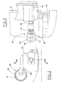
- the station supplying sealing film for a blister band includes a drum 8 rotating about a horizontal axis 41 and featuring, on its periphery, a plurality of carriers 7 for an equal number of reels 6,6s,6a of film 1s,1a.
- the carriers 7 include pneumatic expansion means 45 for locking respective reels 6.
- the pneumatic expansion means are supplied with in-pressure air in known way via a series of channels 38 only schematically shown in the figure.
- the channels 38 are arranged in the drum 8 in known way and are connected to a source of compressed air, not shown, with interposition of valve means.
- valve means as well as all other elements listed later, which must work in mutual time relation, are controlled by an electronic control unit of known type and not shown in the figures.
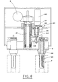
- motor means 2 of known type seen in Figure 8 drive the drum 8 into stepwise rotation by angle steps G corresponding to the angle included between the radiuses passing through two consecutive carriers 7a,7s.
- the motor means 2 are operated by the control unit when the reel 6s is run out and the replacement film reel 6a starts to be used.
- the station 10 where the film from a new reel is spliced with the trailer of the run out reel, is situated below the rotating drum and is of known type, e.g. heat-welding.
- the film 1 passing between the two welding elements 11a, 11b, is directed to the section where it is applied to the blister band, not shown as not related to the present invention ( Figure 1).
- the film 1s comes from an unwinding reel 6s, situated in a position S, with reference to the drum 8 rotation direction, while the film 1a, which is to be spliced with the film 1s, comes from a replacement reel 6a situated in a waiting position A.
- the means 25 are operated for bringing the leader end of the film 1a coming from the replacement reel 6a to the splicing station 10.
- the means 25 moving the leader end of the film 1a include first of all a pair of holding-driving rollers 16,17 situated near each of the carriers 7 of the reels 6,6s,6a.
- rollers 16,17 hold the film before the respective reel 6 is brought near position A and then they drive the film, with the reel in the position A, until its leader is close to the splicing station 10.
- rollers 16,17 are operated by means 30, which act selectively only on the pair of rollers 16,17 situated in the position A.
- these operating means 30 include a horizontal supporting sleeve 31 situated behind the drum 8 and at level of the axis of the roller 16 related to the carrier 7 being in the waiting position A.
- a sliding shaft 32, extending through the sleeve 31, is provided with a bevel-cup coupling 33 fastened to the free end of a rotating stem 23 carried inside the shaft 32 with possibility to turn.
- the stem 23 is driven into rotation by motor means, not shown, coupled thereto, so as to transmit rotating movement and at the same time, allowing it to move longitudinally, according to known constructive techniques.
- the inside of the bevel-cup coupling 33 has a truncated cone section, which can be set in friction engagement with a shank 34, having a complementary profile and being integral with one of the holding-driving rollers 16,17 of each pair.
- the bevel-cup coupling 33 and the conical shank 34 can be joined due to the axial movement of the shaft 32 together with the stem 23, operated by actuator means 35.
- the actuator means 35 include a horizontal pneumatic cylinder connected to the shaft 32 and operated with a suitable stroke.
- Each of the carriers 7 for the reels 6,6s,6a is equipped with means 46 detecting their rotation when the relative carrier takes the position S, in which the respective reel 6s unrolls.
- the rotation sensors 46 include a disc 47, keyed coaxial with a rear head of each of the carriers 7.
- the disc 47 features a plurality of holes 48 spaced along its periphery.
- a sensor 49 connected to the electronic control unit, is situated in the region of the unrolling position S with its active end located along the area of the disc 47 passage.
- a plate 5 is provided for facilitating and guiding the convey of the film 1a.
- the plate 5 moves transversally to the film unrolling direction and separates the film 1a coming from the replacement reel 6a, situated in the position A, from the film 1s coming from the running out reel 6s, situated in the unrolling position S ( Figure 1).
- a stationary plate 3, parallel to the moving plate 5, is situated therebeside.
- the terminal part of the waiting film la is situated between the moving plate 5 and the stationary plate 3.
- the moving plate 5 After the splicing operation, the moving plate 5 must move, so as to allow the reel 6a to shift from the waiting position A to the unrolling position S, due to the stepwise rotation of the drum 8, controlled by the control unit.
- the shifting plate 5 is moved by actuator means 4, formed e.g. by a pneumatic cylinder oriented horizontally and connected to the moving plate by a cross-bar 18.
- actuator means 4 formed e.g. by a pneumatic cylinder oriented horizontally and connected to the moving plate by a cross-bar 18.
- the cylinder 4 determines the horizontal translation of the moving plate 5 in time relation with the drum 8 rotation to shift a reel 6a from the waiting position A to the unrolling position S.
- the station includes also means 20 allowing and determining the drum 8 rotation around a vertical axis, to facilitate the replacement of the run out reels with new reels, without any obstacle due to the presence of the other elements below.
- these means 20 include a rotating platform 21 ( Figure 1), on which the drum 8 is mounted, controlled by the motor means 22 composed of a motor connected to the machine electronic control unit.
- Means 40 are provided to avoid complex and time consuming adjustment operations of the drum 8 transversal position, and therefore also of the film 1 delivered by the reels 6 mounted on the carriers 7. These means 40 automatically adjust the axial movement of the drum carrier axis 41 ( Figure 8) and are operated after the size change of the blister band to be closed with the film 1.
- the means 40 for automatic adjustment of the transversal movement include horizontal translation means 40 formed by a threaded bar 42 rotated axially by a motor 43 and engaged with an internal screw 44 made in the drum carrier axle 41.
- the motor 43 is connected to the electronic control unit and the axis 41 is moved by a distance determined by the control unit and checked by an encoder 36 in relation to the width of the film and the blister band.
- the encoder 36 is linked by means of a belt 37 to the shaft 39 which drives the threaded bar 42.
- This system integrates with the already described horizontal translation means 40 and includes sensors 51,52 detecting the transversal offset of the film 1.
- the sensors 51,52 transversally staggered, are situated in the region where the film passes.
- a sensor 52 is in more internal position and, in case of lacking of the film, it emits a signal, thus limiting the offset toward the film 1 central longitudinal axis.
- the other sensor 51 is in more external position and, when it detects the presence of the film, it emits a signal, thus limiting the offset in direction opposite to the film 1 central longitudinal axis.
- a storage unit 12 for storing the film 1 before splicing is provided for allowing this slicing operation to be performed in due time.
- the stored film is delivered during the splicing without interrupting the application of the film 1 on the blister band, due to stopping of the two films at the splicing station.
- a sensor 13 of known type is situated downstream of the splicing station 10 for detecting the presence of the film, and it can stop the machine if the film 1 breaks during the packaging process.
- the machine After having brought the drum back to the previous position and performed the first splicing operation, the machine is started.
- the moving plate shifts and the reel, from which the film is unrolled, is brought to the unrolling position S.
- the rollers 16,17 can be stopped by a sensor, not shown, that detects when the film edge reaches the desired area.
- the sensor 49 detects the carrier stopping and the control unit activates the splicing station 10, which blocks the film and welds it, while the storage unit delivers the stored film, thus avoiding any interruption of the packaging process.
- the splicing station 10 opens again, delivering the film 1 which restarts to run, thus feeding again the storage unit 12.
- the moving plate 5 shifts, so as to allow the passage of the film 1a, which translates due to the drum 8 rotation by one step, equal to angle G.
- the moving plate 5 turns back to its normal working position and the holding-driving rollers 16,17 relative to the reel just put in the position A, are activated, so that the leader end of the new reel is repositioned to be ready for a new splicing.
- the sensors 51,52 perform continuously an adjustment by acting on the motor 43 via the control unit, so as to move transversally the axle 41 of the drum 8, thus varying the film off-set from one side to the other.
- the drum transversal position is determined automatically always by the motor 43, which moves transversally the supporting axle 41 of the drum 8.
- the apparatus being the object of the present invention fulfils all the objects specified in the introduction, allowing to perform the size change over in a limited time, by only one operator.
- the running out reel is repetitively substituted with a full reel automatically after each splicing, thus allowing the operation of only one operator for the machine starting.
- the run out reels can be easily substituted due to the 180 degrees rotation of the drum 8 carrier, thus facilitating the operator's intervention.
- the apparatus is automatically arranged and adjusted in relation to the size of the blister band to be sealed, so that the operator does not have to perform long adjustment operations.
- the apparatus is able to automatically control and correct the path of the film to be applied on the blister band making up for possible off-sets.
Landscapes
- Replacement Of Web Rolls (AREA)
- Package Closures (AREA)
- Manufacturing Of Electric Cables (AREA)
Abstract
Claims (15)
- Appareil d'alimentation de film d'étanchéité pour une bande de blister à une station de collage (10), comprenant :un tambour (8) tournant autour d'un essieu horizontal (41) et présentant une pluralité de supports (7) agencés le long de sa périphérie pour recevoir des bobines (6, 6s, 6a) de films (1, 1s, 1a) ;une station (10) pour coller le film (1s) provenant de la bobine de sortie (6s), située dans une position de déroulement (S), avec un film à coller (1a) provenant d'une nouvelle bobine (6a) située dans une position d'attente (A) ;des moyens (25) pour préparer l'extrémité d'attaque du film (1a) provenant de la bobine de remplacement (6a) dans la région de la station de collage (10) ;ladite station étant caractérisée en ce qu'elle comprend également des moyens (20) permettant et déterminant une rotation du tambour (8) autour d'un axe vertical, des moyens (40) pour régler automatiquement le mouvement axial de l'axe de support de tambour suite au changement de taille de la bande de blister destinée à être fermée avec ledit film (1), et des moyens (40, 51, 52) pour le contrôle et le réglage automatique du décalage latéral du film d'étanchéité.
- Appareil selon la revendication 1, caractérisé en ce que lesdits moyens (25) pour préparer l'extrémité d'attaque du film (1a) comprennent :une paire de rouleaux d'entraînement de support (16, 17) situés à proximité de chacun des supports (7) pour que lesdites bobines (6, 6s, 6a) maintiennent le film (1a) avant de placer la bobine respective dans une position d'attente (A) et tirent le film, avec la bobine dans ladite position d'attente (A), jusqu'au dispositif de collage (10) ;des moyens (30) actionnant lesdits rouleaux d'entraînement de support (16, 17) et agissant sélectivement sur la paire desdits rouleaux d'entraînement de support (16, 17) situés dans ladite position d'attente (A) ;une plaque (5), se déplaçant transversalement par rapport à la direction de déroulement du film et ayant pour but d'éloigner le fil (1a) déroulé d'une bobine de remplacement (6a), située dans ladite position d'attente (A), du film (1s) provenant d'une bobine de sortie (6s), située dans ladite position de déroulement (S) avant le collage, et lors du déplacement, afin de permettre au film de remplacement (6a) de passer de la position d'attente (A) à la position de déroulement (S) après le collage, en raison d'une rotation d'un pas du tambour (8).
- Appareil selon la revendication 2, caractérisé en ce que lesdits moyens d'actionnement (30) comprennent un manchon de support horizontal (31) situé derrière le tambour (8) et au niveau du support (7) qui est dans la position d'attente (A), avec un arbre (32), coulissant à l'intérieur du manchon (31) et une tige (23), supportée de manière rotative à l'intérieur de l'arbre (32) et entraînée en rotation axiale, ladite tige (23) étant prévue avec un couplage de bague biseautée (33) ayant une section de cône tronqué, et ayant pour but le couplage par frottement avec une tige (34), ayant un profil complémentaire et étant solidaire avec l'un des rouleaux d'entraînement de support (16, 17), ledit couplage étant une conséquence d'un déplacement axial dudit arbre (32) et de ladite tige (23) actionnée par des actionneurs (35).
- Appareil selon la revendication 3, caractérisé en ce que lesdits actionneurs (35) comprennent un vérin pneumatique orienté horizontalement et raccordé audit arbre (32).
- Appareil selon la revendication 2, caractérisé en ce que ladite plaque (5) se déplaçant transversalement est commandée par des moyens d'actionnement (4) qui déterminent une translation horizontale de ladite plaque mobile (5) en relation temporelle avec une rotation du tambour (8) imposée pour faire passer une bobine (6a) de la position d'attente (A) à la position de déroulement (S).
- Appareil selon la revendication 1, caractérisé en ce que lesdits moyens (20) permettant et déterminant la rotation dudit tambour (8) autour d'un axe vertical, comprennent une plateforme rotative (21), sur laquelle le tambour (8) est monté, commandée par les moyens moteur (22).
- Appareil selon la revendication 1, caractérisé en ce que lesdits moyens (40) réglant automatiquement le mouvement axial de l'axe de support de tambour (41) après le changement de taille déclaré de la bande de blister destinée à être fermée avec le film (1), comprennent des moyens de translation horizontale (40) agissant sur ledit axe de support de tambour (41) supportant ledit tambour (8).
- Appareil selon la revendication 7, caractérisé en ce que lesdits moyens de translation horizontale comprennent une barre filetée (42), entraînée en rotation axiale par le moteur (43), et mise en prise avec une vis interne (44) fixée audit axe de support de tambour (41).
- Appareil selon la revendication 1, caractérisé en ce que lesdits moyens pour préparer automatiquement le décalage latéral du film d'étanchéité par rapport à la bande de blister, comprennent des moyens de translation horizontale (40) agissant sur ledit axe de support de tambour (41) supportant ledit tambour (8) et des moyens de capteur (51, 52) pour détecter le déplacement transversal du film (1).
- Appareil selon la revendication 9, caractérisé en ce que lesdits moyens de translation horizontale comprennent une barre filetée (42), entraînée en rotation axiale par un moteur (43) et mise en prise avec une vis interne (44) réalisée dans ledit essieu de support de tambour (41).
- Appareil selon la revendication 9, caractérisé en ce que lesdits moyens de capteur (51, 52) comprennent deux capteurs situés dans la région dans laquelle le film passe et est décalé transversalement en quinconce, avec un capteur (52) dans une position plus interne, prévu dans le cas de manque de film, pour émettre un signal, limitant ainsi le décalage vers l'axe longitudinal central du film (1), et avec un capteur (51) dans une position plus externe, prévue lorsqu'il détecte la présence du film, pour émettre un signal, limitant ainsi le décalage dans la direction opposée à l'axe longitudinal central du film (1).
- Appareil selon la revendication 1, caractérisé en ce que chacun desdits supports (7) des bobines (6, 6s, 6a) est équipé avec des moyens (46) qui permettent de détecter leur rotation lorsque les bobines sont situées dans la position de déroulement (S), dans laquelle la bobine (6s) respective se déroule.
- Appareil selon la revendication 12, caractérisé en ce que lesdits capteurs de rotation (46) desdits supports (7) comprennent un disque (47), claveté de manière coaxiale avec une tête arrière du support (7) respectif et présentant une pluralité de trous (48) espacés le long de sa périphérie, avec un capteur (49) situé en correspondance à ladite position de déroulement (S), afin d'être situé à côté dudit disque (47) et détecter le passage des trous (48) en face de son extrémité active pendant la rotation du support (7).
- Appareil selon la revendication 1, caractérisé en ce qu'il comprend une unité de stockage (12) pour stocker ledit film (1), afin de permettre l'opération de collage sans interrompre l'application du film sur la bande de blister.
- Appareil selon la revendication 1, caractérisé en ce que lesdits supports (7) comprennent des moyens pneumatiques (45) pour bloquer les bobines (6) respectives.
Applications Claiming Priority (3)
| Application Number | Priority Date | Filing Date | Title |
|---|---|---|---|
| ITBO970155 | 1997-03-18 | ||
| IT97BO000155A IT1292805B1 (it) | 1997-03-18 | 1997-03-18 | Stazione di alimentazione della pellicola di sigillatura di un nastro alveolato. |
| PCT/IB1998/000376 WO1998041464A1 (fr) | 1997-03-18 | 1998-03-16 | Debiteur de film de recouvrement pour bande de blisters |
Publications (2)
| Publication Number | Publication Date |
|---|---|
| EP1027272A1 EP1027272A1 (fr) | 2000-08-16 |
| EP1027272B1 true EP1027272B1 (fr) | 2006-06-28 |
Family
ID=11342118
Family Applications (1)
| Application Number | Title | Priority Date | Filing Date |
|---|---|---|---|
| EP98905589A Expired - Lifetime EP1027272B1 (fr) | 1997-03-18 | 1998-03-16 | Debiteur de film de recouvrement pour bande de blisters |
Country Status (6)
| Country | Link |
|---|---|
| US (1) | US6397915B1 (fr) |
| EP (1) | EP1027272B1 (fr) |
| JP (1) | JP2001515447A (fr) |
| DE (1) | DE69835098T2 (fr) |
| IT (1) | IT1292805B1 (fr) |
| WO (1) | WO1998041464A1 (fr) |
Families Citing this family (15)
| Publication number | Priority date | Publication date | Assignee | Title |
|---|---|---|---|---|
| DE10008612A1 (de) * | 2000-02-24 | 2001-09-13 | Bhs Corr Masch & Anlagenbau | Vorrichtung zum Spleißen von Bahnen, insbesondere von Paierbahnen für die Herstellung von Wellpappe |
| ITBO20000402A1 (it) * | 2000-07-06 | 2002-01-06 | Marchesini Group Spa | Unita' per l' alimentazione di articoli a un nastro alveolato . |
| US6923880B2 (en) * | 2002-11-19 | 2005-08-02 | Keene Technology Inc., | Film splicer apparatus and method for splicing a film used for bagging snack foods |
| JP2005035558A (ja) * | 2003-07-16 | 2005-02-10 | Fuji Photo Film Co Ltd | 包装装置及び包装方法 |
| FI120192B (fi) * | 2007-03-30 | 2009-07-31 | Metso Paper Inc | Hylsynlukituslaite |
| KR20140002342A (ko) * | 2012-06-29 | 2014-01-08 | (주)제이브이엠 | 약제 자동 포장기의 포장지 공급장치 |
| US11225390B2 (en) * | 2017-05-19 | 2022-01-18 | Philip Morris Products S.A. | Method and apparatus for feeding and splicing sheet of material wound in a bobbin |
| CN108216729A (zh) * | 2018-02-05 | 2018-06-29 | 佛山市粤金海机械设备有限公司 | 一种铝材贴膜快速换膜调节装置 |
| CN109879037B (zh) * | 2019-04-09 | 2024-02-13 | 瑞光(上海)电气设备有限公司 | 一种少尾料接料系统及其控制方法 |
| KR102738521B1 (ko) * | 2019-12-12 | 2024-12-04 | 현대자동차 주식회사 | 헤어핀 타입 고정자 코일 성형 시스템용 코일 공급 장치 및 작동방법 |
| US12473168B2 (en) | 2020-10-12 | 2025-11-18 | Crc S.R.L. | Unwinder with automatic switching of the unwinding roll |
| IT202000023980A1 (it) * | 2020-10-12 | 2022-04-12 | Crc S R L | Svolgitore con cambio automatico della bobina in svolgimento |
| IT202000023974A1 (it) * | 2020-10-12 | 2022-04-12 | Crc S R L | Svolgitore di prodotto sottile in velo avvolto in bobina, con estrazione della bobina facilitata |
| CN114455358B (zh) * | 2022-01-21 | 2023-12-19 | 浙江班萘特复合材料股份有限公司 | 一种无孔隔离膜复合材料生产设备及其工艺 |
| JP7813667B2 (ja) * | 2022-06-28 | 2026-02-13 | 株式会社東京自働機械製作所 | 包材供給装置 |
Family Cites Families (8)
| Publication number | Priority date | Publication date | Assignee | Title |
|---|---|---|---|---|
| GB534445A (en) * | 1939-07-14 | 1941-03-06 | Goss Printing Press Co Ltd | Improvements in or relating to web roll supporting mechanisms for printing presses |
| JPS5978060A (ja) * | 1982-10-27 | 1984-05-04 | Ckd Corp | フイルムの自動連続供給装置 |
| DE3342080A1 (de) * | 1983-11-22 | 1985-05-30 | Focke & Co, 2810 Verden | Vorrichtung zur aufnahme von bobinen |
| NL8803121A (nl) * | 1988-12-21 | 1990-07-16 | Oce Nederland Bv | Werkwijze voor het aanvoeren van baanvormig materiaal, inrichting daarvoor, alsmede kopieerapparaat voorzien van zo'n inrichting. |
| US5323178A (en) * | 1991-08-23 | 1994-06-21 | Eastman Kodak Company | Material supply carousel |
| JP2702022B2 (ja) * | 1991-10-31 | 1998-01-21 | 日本たばこ産業株式会社 | ウエブリールの自動交換装置 |
| DE4336298A1 (de) * | 1993-10-25 | 1995-04-27 | Bachofen & Meier Maschf | Abwickelvorrichtung mit einer Spliceeinrichtung |
| US5849123A (en) * | 1995-12-20 | 1998-12-15 | Eastman Kodak Company | Apparatus and method for aligning webs |
-
1997
- 1997-03-18 IT IT97BO000155A patent/IT1292805B1/it active IP Right Grant
-
1998
- 1998-03-16 JP JP54027798A patent/JP2001515447A/ja not_active Ceased
- 1998-03-16 DE DE69835098T patent/DE69835098T2/de not_active Expired - Fee Related
- 1998-03-16 US US09/381,346 patent/US6397915B1/en not_active Expired - Fee Related
- 1998-03-16 WO PCT/IB1998/000376 patent/WO1998041464A1/fr not_active Ceased
- 1998-03-16 EP EP98905589A patent/EP1027272B1/fr not_active Expired - Lifetime
Also Published As
| Publication number | Publication date |
|---|---|
| DE69835098D1 (de) | 2006-08-10 |
| WO1998041464A1 (fr) | 1998-09-24 |
| ITBO970155A0 (it) | 1997-03-18 |
| DE69835098T2 (de) | 2007-01-18 |
| ITBO970155A1 (it) | 1998-09-18 |
| JP2001515447A (ja) | 2001-09-18 |
| EP1027272A1 (fr) | 2000-08-16 |
| US6397915B1 (en) | 2002-06-04 |
| IT1292805B1 (it) | 1999-02-11 |
Similar Documents
| Publication | Publication Date | Title |
|---|---|---|
| EP1027272B1 (fr) | Debiteur de film de recouvrement pour bande de blisters | |
| US4899520A (en) | Packaging apparatus and method | |
| US6038839A (en) | Longitudinal seam sealer for polyethylene material | |
| US4526638A (en) | Apparatus and method for joining webs | |
| EP0668213B1 (fr) | Dispositif et procédé pour alimenter et raccorder un film d'emballage | |
| US4989397A (en) | In-line package strapping system | |
| US7854105B2 (en) | Film wrapping machine utilizing two film carriage assemblies to effectively perform film change operations | |
| US8424271B2 (en) | Process for wrapping loads, in particular palletised loads, and relative system | |
| US4694714A (en) | Process and apparatus for changing reels in connection with packaging machines | |
| JPS6238207B2 (fr) | ||
| GB2260532A (en) | A device for splicing strips of limited transverse dimensions automatically | |
| WO2019145223A2 (fr) | Ensemble magasin pour machine à emballer, machine à emballer dotée d'un ensemble magasin et procédé d'actionnement d'une machine à emballer | |
| US20050034580A1 (en) | Device for transversally cutting into portions a continuous strip of containers | |
| US4781215A (en) | Package wrapping machine system | |
| US20040035975A1 (en) | Strip feed unit and method, and reel end pickup method | |
| US20050132664A1 (en) | Device for feeding and cutting film in machines for conditioning products | |
| EP1002727A2 (fr) | Dispositif d'assemblage et de transport, en particulier pour système d'emballage | |
| US20020007616A1 (en) | Apparatus and method for applying endless bands to cartons | |
| EP0968127A2 (fr) | Appareil alimentant en film thermoformable une emballeuse sous blister ou analogue des articles | |
| US20260077896A1 (en) | Machine for forming filter bags for infusion products | |
| AU696955B2 (en) | Continuously forming and presenting bags for packaging | |
| JP2841215B2 (ja) | 包装方法及び装置 | |
| WO2025061597A1 (fr) | Unité de magasin pour machine à emballer, machine à emballer dotée d'une unité de magasin et procédé de chargement d'une unité de magasin | |
| WO2000035755A1 (fr) | Appareil et procede d'application de bandes sans fin sur des cartons | |
| CN121871877A (zh) | 一种对折膜自动装袋机 |
Legal Events
| Date | Code | Title | Description |
|---|---|---|---|
| PUAI | Public reference made under article 153(3) epc to a published international application that has entered the european phase |
Free format text: ORIGINAL CODE: 0009012 |
|
| 17P | Request for examination filed |
Effective date: 19990916 |
|
| AK | Designated contracting states |
Kind code of ref document: A1 Designated state(s): DE FR GB IT |
|
| GRAP | Despatch of communication of intention to grant a patent |
Free format text: ORIGINAL CODE: EPIDOSNIGR1 |
|
| GRAS | Grant fee paid |
Free format text: ORIGINAL CODE: EPIDOSNIGR3 |
|
| GRAA | (expected) grant |
Free format text: ORIGINAL CODE: 0009210 |
|
| AK | Designated contracting states |
Kind code of ref document: B1 Designated state(s): DE FR GB IT |
|
| PG25 | Lapsed in a contracting state [announced via postgrant information from national office to epo] |
Ref country code: IT Free format text: LAPSE BECAUSE OF FAILURE TO SUBMIT A TRANSLATION OF THE DESCRIPTION OR TO PAY THE FEE WITHIN THE PRESCRIBED TIME-LIMIT;WARNING: LAPSES OF ITALIAN PATENTS WITH EFFECTIVE DATE BEFORE 2007 MAY HAVE OCCURRED AT ANY TIME BEFORE 2007. THE CORRECT EFFECTIVE DATE MAY BE DIFFERENT FROM THE ONE RECORDED. Effective date: 20060628 |
|
| REG | Reference to a national code |
Ref country code: GB Ref legal event code: FG4D |
|
| REF | Corresponds to: |
Ref document number: 69835098 Country of ref document: DE Date of ref document: 20060810 Kind code of ref document: P |
|
| ET | Fr: translation filed | ||
| PGFP | Annual fee paid to national office [announced via postgrant information from national office to epo] |
Ref country code: GB Payment date: 20070226 Year of fee payment: 10 |
|
| PGFP | Annual fee paid to national office [announced via postgrant information from national office to epo] |
Ref country code: DE Payment date: 20070307 Year of fee payment: 10 |
|
| PLBE | No opposition filed within time limit |
Free format text: ORIGINAL CODE: 0009261 |
|
| STAA | Information on the status of an ep patent application or granted ep patent |
Free format text: STATUS: NO OPPOSITION FILED WITHIN TIME LIMIT |
|
| 26N | No opposition filed |
Effective date: 20070329 |
|
| PGFP | Annual fee paid to national office [announced via postgrant information from national office to epo] |
Ref country code: IT Payment date: 20070607 Year of fee payment: 10 |
|
| PGFP | Annual fee paid to national office [announced via postgrant information from national office to epo] |
Ref country code: FR Payment date: 20070227 Year of fee payment: 10 |
|
| GBPC | Gb: european patent ceased through non-payment of renewal fee |
Effective date: 20080316 |
|
| REG | Reference to a national code |
Ref country code: FR Ref legal event code: ST Effective date: 20081125 |
|
| PG25 | Lapsed in a contracting state [announced via postgrant information from national office to epo] |
Ref country code: DE Free format text: LAPSE BECAUSE OF NON-PAYMENT OF DUE FEES Effective date: 20081001 |
|
| PG25 | Lapsed in a contracting state [announced via postgrant information from national office to epo] |
Ref country code: FR Free format text: LAPSE BECAUSE OF NON-PAYMENT OF DUE FEES Effective date: 20080331 |
|
| PG25 | Lapsed in a contracting state [announced via postgrant information from national office to epo] |
Ref country code: GB Free format text: LAPSE BECAUSE OF NON-PAYMENT OF DUE FEES Effective date: 20080316 |
|
| PG25 | Lapsed in a contracting state [announced via postgrant information from national office to epo] |
Ref country code: IT Free format text: LAPSE BECAUSE OF NON-PAYMENT OF DUE FEES Effective date: 20080316 |