EP1028076A2 - Verfahren zum Transport von einem Bogen durch eine Bearbeitungsstation - Google Patents
Verfahren zum Transport von einem Bogen durch eine Bearbeitungsstation Download PDFInfo
- Publication number
- EP1028076A2 EP1028076A2 EP00300630A EP00300630A EP1028076A2 EP 1028076 A2 EP1028076 A2 EP 1028076A2 EP 00300630 A EP00300630 A EP 00300630A EP 00300630 A EP00300630 A EP 00300630A EP 1028076 A2 EP1028076 A2 EP 1028076A2
- Authority
- EP
- European Patent Office
- Prior art keywords
- sheet
- working area
- veneer
- working
- feed means
- Prior art date
- Legal status (The legal status is an assumption and is not a legal conclusion. Google has not performed a legal analysis and makes no representation as to the accuracy of the status listed.)
- Granted
Links
- 238000000034 method Methods 0.000 title claims abstract description 25
- 238000007731 hot pressing Methods 0.000 claims description 7
- 239000002023 wood Substances 0.000 claims description 6
- 238000003825 pressing Methods 0.000 abstract description 6
- 238000012546 transfer Methods 0.000 abstract description 2
- 238000001035 drying Methods 0.000 description 13
- 230000000712 assembly Effects 0.000 description 4
- 238000000429 assembly Methods 0.000 description 4
- 239000000463 material Substances 0.000 description 4
- 238000011144 upstream manufacturing Methods 0.000 description 3
- 238000005452 bending Methods 0.000 description 2
- 239000000835 fiber Substances 0.000 description 2
- 238000012423 maintenance Methods 0.000 description 2
- 238000010276 construction Methods 0.000 description 1
- 238000007796 conventional method Methods 0.000 description 1
- 238000001514 detection method Methods 0.000 description 1
- 230000000694 effects Effects 0.000 description 1
- 230000003028 elevating effect Effects 0.000 description 1
- 239000011094 fiberboard Substances 0.000 description 1
- 238000004519 manufacturing process Methods 0.000 description 1
- 238000012986 modification Methods 0.000 description 1
- 230000004048 modification Effects 0.000 description 1
- 230000003287 optical effect Effects 0.000 description 1
- 230000002093 peripheral effect Effects 0.000 description 1
- 239000011120 plywood Substances 0.000 description 1
- 230000035939 shock Effects 0.000 description 1
- 230000001360 synchronised effect Effects 0.000 description 1
Images



Classifications
-
- B—PERFORMING OPERATIONS; TRANSPORTING
- B23—MACHINE TOOLS; METAL-WORKING NOT OTHERWISE PROVIDED FOR
- B23Q—DETAILS, COMPONENTS, OR ACCESSORIES FOR MACHINE TOOLS, e.g. ARRANGEMENTS FOR COPYING OR CONTROLLING; MACHINE TOOLS IN GENERAL CHARACTERISED BY THE CONSTRUCTION OF PARTICULAR DETAILS OR COMPONENTS; COMBINATIONS OR ASSOCIATIONS OF METAL-WORKING MACHINES, NOT DIRECTED TO A PARTICULAR RESULT
- B23Q5/00—Driving or feeding mechanisms; Control arrangements therefor
-
- B—PERFORMING OPERATIONS; TRANSPORTING
- B65—CONVEYING; PACKING; STORING; HANDLING THIN OR FILAMENTARY MATERIAL
- B65H—HANDLING THIN OR FILAMENTARY MATERIAL, e.g. SHEETS, WEBS, CABLES
- B65H5/00—Feeding articles separated from piles; Feeding articles to machines
- B65H5/06—Feeding articles separated from piles; Feeding articles to machines by rollers or balls, e.g. between rollers
- B65H5/062—Feeding articles separated from piles; Feeding articles to machines by rollers or balls, e.g. between rollers between rollers or balls
-
- B—PERFORMING OPERATIONS; TRANSPORTING
- B65—CONVEYING; PACKING; STORING; HANDLING THIN OR FILAMENTARY MATERIAL
- B65H—HANDLING THIN OR FILAMENTARY MATERIAL, e.g. SHEETS, WEBS, CABLES
- B65H5/00—Feeding articles separated from piles; Feeding articles to machines
-
- B—PERFORMING OPERATIONS; TRANSPORTING
- B65—CONVEYING; PACKING; STORING; HANDLING THIN OR FILAMENTARY MATERIAL
- B65H—HANDLING THIN OR FILAMENTARY MATERIAL, e.g. SHEETS, WEBS, CABLES
- B65H2301/00—Handling processes for sheets or webs
- B65H2301/40—Type of handling process
- B65H2301/44—Moving, forwarding, guiding material
- B65H2301/442—Moving, forwarding, guiding material by acting on edge of handled material
- B65H2301/4421—Moving, forwarding, guiding material by acting on edge of handled material by abutting edge
-
- B—PERFORMING OPERATIONS; TRANSPORTING
- B65—CONVEYING; PACKING; STORING; HANDLING THIN OR FILAMENTARY MATERIAL
- B65H—HANDLING THIN OR FILAMENTARY MATERIAL, e.g. SHEETS, WEBS, CABLES
- B65H2513/00—Dynamic entities; Timing aspects
- B65H2513/40—Movement
- B65H2513/41—Direction of movement
Definitions
- the present invention relates to a method of conveying or transferring a sheet material through a working apparatus. More specifically, the invention relates to a method of transferring a sheet of wood veneer through a hot press type drying apparatus.
- a veneer dryer having a pair of hot plates which are disposed one above the other for drying a sheet of wood veneer by hot pressing the sheet therebetween.
- a green or undried veneer sheet is moved from one end of the dryer to a predetermined position within the dryer, where the veneer sheet is hot pressed for a predetermined length of tome for drying to a desired extent. After the drying has been completed, the dried veneer sheet is moved out of the apparatus through the opposite end thereof.
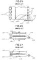
- FIGS. 24 to 27 show a typical hot press type veneer dryer. It is to be understood that in describing the drawings only those portions of the construction of the dryer has been shown which enable those skilled in the art to readily understand the underlying principle and concept of the present invention.
- FIG. 24 which is a schematic side view of the hot plate dryer
- FIG. 25 which is a fragmentary plan view as seen from dash-and-dot line A-A in arrow direction
- a pair of hot plates 101, 103 are disposed one above the other, of which the lower plate 101 is stationary while the upper plate 103 is movable toward and away from the stationary lower plate 101, as indicated by arrow.
- the hot plates 101, 103 have a longitudinal dimension L1, respectively, corresponding to the maximum working length of the dryer, while each veneer sheet 115 to be worked by the dryer has a longitudinal dimension L2 as measured in the same direction, and this L2 is smaller than L1, as best seen FIG. 6.
- a plurality of pairs of delivery rolls 107 mounted on drive shafts, respectively, of which the lower rolls are constantly rotatable in the arrow direction, while the upper idle rolls 107 are spaced apart from their corresponding lower rolls at an appropriate distance for holding therebetween and conveying a dried veneer sheet out of the dryer.
- a veneer sheet loading device is provided on lateral side of the dryer adjacent to the feed rolls 105, which includes an arm 113 reciprocally swingable about a pivot 111 and having at one end thereof a pusher 109.
- the arm 113 is normally located in its inoperative position as indicated by solid line and swingable by means of any suitable actuator such as pneumatic or hydraulic cylinder to its operative positions 109a and 109b indicated by phantom lines, respectively.
- a similar device including an arm 113 and its related parts is located on the opposite side of the dryer in a symmetrical relation with respect to longitudinal center line (not shown) of the dryer.
- a sheet of green veneer 115 is conveyed by the feed rolls 105 toward the dryer and inserted between the hot plates 101, 103. Movement of the veneer sheet 115 is stopped when the trailing end of the sheet 115 has just moved past the feed rolls 105 as shown in FIGS. 24, 25 and, therefore, conveying action of the rolls 105 is imparted to the veneer sheet 115 no more. As shown in FIGS. 24, 25, the veneer sheet 105 is partially inserted between the hot plates 101, 103 with part of its trailing end portion lying outside the hot plates 101, 103. Subsequently, the loading devices are actuated simultaneously to swing the arms 113 inward, or counter clockwise direction as seen in FIG. 25 for the arm 113 illustrated in FIG.
- the pushers 109 are swung into contact with the trailing end of the veneer sheet 105, then moving the sheet along the upper surface of the stationary hot plate 101.
- the arms 113 are turned until the pushers 109 reach position 109a, where the veneer sheet 115 lies well within the working area or the longitudinal extension of the hot plates 101, 103 as shown in FIG. 26.
- the arms 113 are swung back to their original position shown in FIG. 25, and the upper hot plate 103 is lowered as indicated by arrow in FIG. 26 to press and heat the veneer sheet for a predetermined length of time for drying.
- the upper hot plate 103 is elevated as shown in FIG. 27 and the arms 113 are swung again then to position 19b to move the dried veneer sheet 115 from the position of FIG. 26 to a position shown in FIG. 27 where the leading end of the sheet 115 can be caught and held by the delivery rolls 107.
- the dried veneer sheet 155 is conveyed by the delivery rolls 107 out of the dryer to any subsequent working station (not shown).
- an object of the invention is to provide a method of transferring a sheet such as wood veneer sheet through a working apparatus which dispenses with the above-described veneer sheet loading equipment or similar devices.
- a working apparatus in which a method of the invention is performed has a working area with a dimension L1 as measured along the direction in which the sheet is transferred, while a sheet to be transferred through the working apparatus has a dimension L2, as measured along the same direction, which is smaller than the dimension L1.
- the working apparatus includes feed means in the form of rotatable rolls disposed adjacent to one end of the working area and capable of moving the sheet partially or incompletely into the working area with part of the trailing end portion of the sheet lying outside the working area and delivery means such as rotatable rolls disposed adjacent to the opposite end of the working area of the working apparatus for removing the sheet therefrom.
- a first sheet is moved by the feed means partially into the working area.
- a second sheet is moved by the feed means into abutment of the leading end thereof with the trailing end of its preceding first sheet and moved further thereby to cause the second sheet to push its preceding first sheet to a predetermined position within the working area.
- the feed means is stopped and then reversed to move back the second sheet out of the working area.
- the feed means is activated again to move the second sheet into abutment with the trailing end of its preceding worked first sheet and moved further while allowing the second sheet to push the first sheet toward the delivery means.
- the second sheet is moved to a position to which the first sheet was previously moved by the feed means, while the first sheet is removed by the delivery means out of the working area of the apparatus.
- Such steps of operation is repeated to transfer a series of sheets successively through the working apparatus. Since a sheet fed into the working apparatus incompletely can be moved by another sheet that follows to a predetermined position within the working area, loading equipment as described above with reference to prior art apparatus may be dispensed with.
- the step of reversing the feed means to move back the second sheet out of the working area may be omitted.
- a first sheet may be worked as it is with part of its trailing end portion lying outside the working area if such working is acceptable.
- the worked sheet can be removed by moving a second sheet by the feed means into abutment of the leading end thereof with the trailing end of its preceding worked first sheet and further to a position to which the first sheet was previously moved by the feed means, while causing the second sheet to push the first sheet toward the delivery means.
- a first sheet fed incompletely into the working area is moved by being pushed by a second sheet to a predetermined position within the working area of the apparatus. Then, working by the apparatus may be done for the entire of said first sheet and part of the leading end portion of the second sheet which then lies within the working area. By so doing, the step of reversing the feed means may be omitted.
- the second sheet is moved by the feed means to a position to which the first sheet was previously moved by the feed means, so that the first sheet is pushed to move toward the delivery means, which then removes the sheet from the working apparatus.
- the working apparatus may include aligning means in the form a stop member disposed between one end of the working area and the feed means and extending perpendicularly to the extension L1 of the working area of the apparatus for aligning or orienting each sheet straight with respect to the direction in which the sheet is moved by the feed means.
- method of the invention further comprises a step of aligning each sheet by the aligning means before it is moved by the feed means into the working area.
- a hot press type veneer dryer H which includes a pair of hot plates 1, 3 disposed one above the other and each having a longitudinal dimension L1 as measured in the direction in which a veneer sheet 11 is moved through the dryer as will be described later.
- the lower hot plate 1 is stationary while the upper plate 2 is movable toward and away from the stationary hot plate 1 thereby to form a daylight or a space between the plates 1, 3 into which a green or undried veneer sheet 11 may be inserted and hot pressed for drying.
- Each of the veneer sheets 11 has a longitudinal dimension L2 as measured in the same direction and that this dimension L2 is smaller than L1, as most clearly seen in FIG. 6.
- each group of feed rolls 5, 7 includes a pair of roll assemblies disposed one above the other and each assembly comprising a common shaft extending perpendicularly to the longitudinal extension L1 of the hot plates 1, 3 and a plurality of rolls mounted on the shaft at a spaced intervals in the same manner as in the case of feed rolls 105 shown in FIG. 25 and described with reference to a conventional veneer sheet transferring method.
- the lower feed rolls 5, 7 are rotatable at the same speed in forward and reverse directions as indicated by arrows, for example, in FIGS.
- the upper feed rolls 5, 7 are idle and spaced apart from their driven counterparts so that the veneer sheet 11 may be held therebetween and moved in either direction depending on the direction in which the lower roll 5, 7 are then driven to rotate.
- each assembly Adjacent to the opposite downstream end of the dryer H is provided a pair of delivery roll assemblies disposed one above the other, each assembly comprising a common shaft extending parallel to the shaft fro the feed rolls 5, 7 and a plurality of delivery rolls 9 mounted on the shaft at a spaced intervals in the same manner as in the case of feed rolls 5, 7.
- the lower delivery rolls 9 are positively driven to rotate in the arrow direction at a peripheral speed which is the same as or slightly higher than that of the driven feed rolls 5, 7 when they are rotating in forward direction.
- the upper delivery rolls 9 are idle and spaced apart from their driven counterparts so that the veneer sheet 11 may be caught and held therebetween and moved leftward as seen in FIG. 1.
- the veneer dryer H further includes an optical switch 13 of diffuse reflection type which is located and operable as a sensor so as to detect the trailing end of a veneer sheet 11a that follows its preceding veneer sheet 11 as shown in FIG. 5 and as will be described in detail in later part hereof.
- the sensor 13 is adapted to generate a signal to a control (not shown) which in turn controls the operation of the lower driven feed rolls 5, 7 in response to such signal from the sensor 13.
- each veneer sheet should be transferred through the dryer in such a position that its general fiber orientation is directed along the path in which the veneer sheet is moved for the sake of stability in transferring operation.
- veneer sheet should be thick enough, for example 3 mm or more, to resist abutting shock as will be described in detail later, although the invention does not limit the sheet thickness to the above exemplified dimension. It is also noted that, for the sake of illustration in the drawings for better understanding of the invention, veneer sheet thickness is shown much larger than actual.
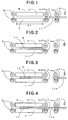
- FIGS. 1 to 12 show the preferred embodiment of the present invention.
- the upper hot plate 3 is placed in its elevated position to form a space with the stationary lower plate 1 for receiving therein veneer sheet 11 and the lower feed rolls 5, 7 are being rotated in forward direction as indicated by arrows.
- the first veneer sheet 11 inserted between the top and bottom feed rolls 5, 7 is fed toward the space between the hot plates 1, 3.
- the sheet is stopped at a position between the hot plates 1, 3, as shown in FIG.
- each veneer sheet in FIG. 2 is not necessarily constant, but variable depending on various factors such as surface condition of veneer sheet, the speed at which the feed rolls 5, 7 are driven to rotate, etc.
- a succeeding veneer sheet 11a is fed by the rolls 5, 7, moving forward into abutment with the trailing end of its preceding veneer sheet 11 as shown in FIGS. 3 and 4, whereupon the veneer sheet 11 is pushed forward by the succeeding veneer sheet 11a.
- Forward rotation of the feed rolls 5, 7 is continued with the abutment relation between the leading end of the veneer sheet 11a and the trailing end of its preceding veneer sheet 11 being maintained, until a position shown in FIG. 5 is reached, where the veneer sheet 11 is located entirely within the working area or the longitudinal extension L1 of the hot plates 1, 3.
- This position may be determined by the sensor 13 then detecting the passage of the trailing end of the veneer sheet 11a and simultaneously generating a detection signal to the control, which in turn causes the lower feed rolls 5, 7 to stop their rotation in response to such signal from the sensor 13. Then, the control causes the feed rolls 5, 7 to rotate in reverse direction only for a short period of time, for example one second, to move the succeeding veneer sheet 11a back to a position as shown in FIG. 6.
- the control is operated to generate a signal to move the upper hot plate 3 to its operative position to hot press the veneer sheet 11 by the upper and lower hot plates 1, 3, as shown in FIG. 7.
- This hot pressing is continued for a predetermined length of time for the desired drying effect of veneer sheet 11.
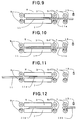
- the hot plate 3 is elevated to its original position as shown in FIG. 8 and the lower feed rolls 5, 7 are driven to rotate in forward direction to move the veneer sheet 11a into abutment with the trailing end of its preceding sheet 11 in the dryer H as shown in FIG. 9 and then pushes the veneer sheet 11 forward as shown in FIG. 10.
- the leading end of the veneer sheet 11 has reached the delivery rolls 9 as shown in FIG. 10, the sheet 11 is moved forward then by the delivery rolls 9.
- the dried veneer sheet 11 can be removed completely out of the dryer H and may be transferred further to any subsequent working station (not shown). Movement of the succeeding veneer sheet 11b is stopped after its trailing end has moved past of the feed rolls 5 adjacent to the hot plates 1, 3, as shown in FIG. 11. Then, a further veneer sheet 11b is conveyed by the feed rolls 5, 7 as shown in FIG. 12, and steps of operation which have been described with reference to FIGS. 4 to 11 are repeated to work veneer sheets successively.
- the sheet transferring method according to the present invention can thus dispense with equipment for loading a sheet to a predetermined position within a working apparatus, such as the one which has been described with reference to FIG. 25. Furthermore, the method of the invention accomplishes transferring successive sheets through the working apparatus by merely controllably operating the feed rolls. These features of the invention can simplify the working apparatus and hence reduce the apparatus cost and facilitates maintenance procedure.
- the feed rolls 5, 7 are stopped and then reversed to cause the succeeding veneer sheet 11a to move back to the position shown in FIG. 6, so that veneer sheets are pressed successively one entire sheet after another as shown in FIG. 7.
- the method of the invention may dispense with the step of reversing the feed rolls 5, 7.
- a veneer sheet dried by being hot pressed with part of either end portion thereof lying outside the hot plates 1, 3 offers no problem for its application
- the step to allow a succeeding veneer sheet to abut against the trailing end of and push its preceding veneer sheet for positioning of the latter veneer sheet at a predetermined position within the working apparatus, as shown for example in FIG. 6, may be omitted.
- a veneer sheet 11 after a veneer sheet 11 has been inserted into the space between the hot plates 1, 3 as shown in FIG. 2, it may be hot pressed as it is with part of its trailing end portion lying outside the hot plates 1, 3 as shown in FIG. 13.
- the dried veneer sheet 11 is removed by the delivery rolls 9 from the drier H and the subsequent veneer sheet 11a is moved to the position shown in FIG. 2 or FIG. 13 to which its preceding veneer sheet was conveyed previously by the feed rolls 5, 7.
- the veneer sheet 11a is hot pressed in the same manner as its preceding veneer sheet 11, and steps of operation shown in FIGS. 2, 13 and 14 are repeated for drying veneer sheets successively.
- method of this embodiment can dispense with the steps of reversing the feed rolls 5, 7.
- Operation to reverse the feed rolls 5, 7 may be also omitted in the modified embodiment illustrated in FIGS. 15 and 16.
- firstly steps of operation shown in FIGS. 1 to 5 are performed. After the veneer sheet 11 has been pushed by its succeeding sheet 11a and located entirely within the pressing area of the hot plates 1, 3 and the feed rolls 5, 7 are stopped as shown in FIG. 5, the upper hot plate 3 is lowered to its operative pressing position as shown in FIG. 15, with the result that the entire veneer sheet 11 and part of the leading end portion of its succeeding veneer sheet 11a are hot pressed simultaneously for drying. After the drying has been completed, the hot plate 3 is moved to its elevated position and the feed rolls 5, 7 are activated again, so that the veneer sheet 11a is moved forward while pushing its preceding sheet 11 as shown in FIG. 16. The veneer sheet 11 is removed from the hot plates 1, 3 when its leading end reaches the delivery rolls 9. The succeeding veneer sheet 11a is moved further to the position as shown in FIG. 2, and thereafter steps of FIGS. 3 to 5, 15 and 16 are repeated.
- Reference numeral 15 in the drawings designates a stop 15 located between the upstream end of the lower stationary hot plate 1 and the feed rolls 5 adjacent thereto.
- the stop 15 extends perpendicularly to the longitudinal extension L1 of the hot plates 1, 3 and it is operable from a control signal from the control (not shown) to swing as indicated by double-head arrow between upright operative position (solid line) and inoperative position (dotted line).
- a first veneer sheet 17 is moved by the feed rolls 5, 7 into contact with the stop 15 as shown in FIG. 17.
- a veneer sheet being moved in a slightly oblique position can be oriented or aligned straight with respect to the direction in which the sheet is to be fed into the dryer H.
- slippage occurs for a short period of time between the veneer sheet surfaces and the feed rolls 5, 7 during such aligning operation.
- the stop 15 is turned to its dotted line position to allow the sheet 17 to move forward by the feed rolls 5, 7 to a position between the hot plates 1, 3 with part of its trailing end portion lying outside the longitudinal extension L1 of the hot plates 1, 3, as shown in FIG. 18.
- the stop 15 When the veneer sheet 17 has moved past the stop 15, the stop 15 is swung back to its upright position and a succeeding veneer sheet 17a is fed by the feed rolls 5, 7 into contact with the stop 15, as shown in FIG. 18, to be aligned in the same manner as its preceding veneer sheet 17.
- the stop 15 is turned down to its dotted position to allow the veneer sheet 17a to moved forward into abutment contact with the trailing end of its preceding veneer sheet 17 as shown in FIG. 19 and pushes the sheet 17 to a predetermined position within the space between the hot plates 1, 3 as shown in FIG. 20. Since the distance from a given point of the dryer H to the stop 15 is known and the lower feed rolls are driven at a constant speed, movement of the veneer sheet 17 to the above predetermined position (FIG. 20) may be accomplished by counting time by a timer (not shown) from the moment when the stop 15 is turned inoperative and stopping the feed rolls 5, 7 when a predetermined length of time corresponding to the distance the veneer sheet 17 should be moved to reach the position of FIG. 20 has been counted by the timer.
- the feed rolls 5, 7 are reversed to move the succeeding sheet 17a to a position clear of the hot plates 1, 3 and, simultaneously, the upper hot plate 3 is lowered to press the veneer sheet 17, as shown in FIG. 21.
- the hot plate 3 is elevated and the feed rolls 5, 7 are driven forward to move the subsequent veneer sheet 17a into the space between the hot plates 1, 3, so that its preceding veneer sheet 17 is pushed thereby forward until its leading end is held between the delivery rolls 9, which then removes the sheet 17 out of the dryer H, and the second veneer sheet 17a is placed at the position to which its preceding sheet 17 was moved previously by the feed rolls 5, 7, as shown in FIG. 22.
- the stop 15 is swung to its upright position to stop a further incoming veneer sheet 17b, which is the same condition as that of FIG. 18. Steps of operation of FIGS. 18 to 22 are repeated to successively feeding and pressing veneer sheets.
- each veneer sheet should be transferred with its general fiber orientation directed along the direction in which it is moved, for veneer sheet to have a strength to resist the above bending force.
- veneer sheets to be transferred through a working apparatus according to the present invention should be thick enough for the sake of stability of transferring operation.
- the feed rolls 5, 7 may take any form of conveying means operable to feed sheet material, such as conveyer belts trained round pulleys.
- conveying means operable to feed sheet material
- conveyer belts trained round pulleys such as conveyer belts trained round pulleys.
- the hot press type veneer dryer is not limited to the structure as illustrated in the drawings and the above description of various embodiments, but dryers of other structures may be contemplated for use in performing the method of the invention.
Landscapes
- Engineering & Computer Science (AREA)
- Mechanical Engineering (AREA)
- Veneer Processing And Manufacture Of Plywood (AREA)
- Processing And Handling Of Plastics And Other Materials For Molding In General (AREA)
- Drying Of Solid Materials (AREA)
Applications Claiming Priority (2)
| Application Number | Priority Date | Filing Date | Title |
|---|---|---|---|
| JP7069899 | 1999-02-09 | ||
| JP7069899 | 1999-02-09 |
Publications (3)
| Publication Number | Publication Date |
|---|---|
| EP1028076A2 true EP1028076A2 (de) | 2000-08-16 |
| EP1028076A3 EP1028076A3 (de) | 2001-01-10 |
| EP1028076B1 EP1028076B1 (de) | 2002-11-13 |
Family
ID=13439110
Family Applications (1)
| Application Number | Title | Priority Date | Filing Date |
|---|---|---|---|
| EP00300630A Expired - Lifetime EP1028076B1 (de) | 1999-02-09 | 2000-01-28 | Verfahren zum Transport von einem Bogen durch eine Bearbeitungsstation |
Country Status (10)
| Country | Link |
|---|---|
| US (1) | US6363845B1 (de) |
| EP (1) | EP1028076B1 (de) |
| KR (1) | KR100338884B1 (de) |
| CN (1) | CN1184070C (de) |
| CA (1) | CA2298255C (de) |
| DE (1) | DE60000746T2 (de) |
| ID (1) | ID24777A (de) |
| MY (1) | MY118056A (de) |
| NZ (1) | NZ502732A (de) |
| TW (1) | TW466208B (de) |
Families Citing this family (12)
| Publication number | Priority date | Publication date | Assignee | Title |
|---|---|---|---|---|
| DE10356217B3 (de) * | 2003-12-02 | 2005-04-14 | Heinrich Kuper Gmbh & Co Kg | Vorrichtung zum Einzug von Furnierstreifen |
| EP2805801B1 (de) * | 2013-05-24 | 2020-10-21 | Faurecia Interieur Industrie | Verfahren zur Verarbeitung eines Furnierholzes |
| CN105690505A (zh) * | 2016-03-10 | 2016-06-22 | 广西南宁侨盛木业有限责任公司 | 一种板材传送、定型装置 |
| CN106629003A (zh) * | 2016-11-28 | 2017-05-10 | 南京汉安科技实业有限公司 | 转盘式出料装置 |
| CN106956936A (zh) * | 2017-04-01 | 2017-07-18 | 大亚人造板集团有限公司强化地板分公司 | 带有自动进板装置的木板热压机及其使用方法 |
| CN107443927A (zh) * | 2017-08-21 | 2017-12-08 | 顾东海 | 一种错题识别分类装置及其工作方法 |
| CN109849128A (zh) * | 2019-01-17 | 2019-06-07 | 杭州第一技师学院 | 一种自动劈青机 |
| CN113581821B (zh) * | 2020-04-30 | 2023-04-14 | 晟通科技集团有限公司 | 输送装置及设有其的加工设备 |
| JP7567202B2 (ja) * | 2020-05-22 | 2024-10-16 | セイコーエプソン株式会社 | 繊維構造体製造装置、繊維構造体製造方法、および繊維構造体 |
| CN113211566B (zh) * | 2021-05-11 | 2022-07-15 | 柳州市东阳木业有限公司 | 一种胶合板生产自动化加工系统及加工方法 |
| CN113803967B (zh) * | 2021-08-31 | 2022-08-02 | 江苏文泰节能新材料有限公司 | 一种高强度内墙板用层压式烘干机 |
| CN118385953B (zh) * | 2024-07-01 | 2024-12-17 | 山东建明伟业建设工程有限公司 | 一种金属门窗框铝型材综合加工装置 |
Family Cites Families (8)
| Publication number | Priority date | Publication date | Assignee | Title |
|---|---|---|---|---|
| DE1207593B (de) * | 1965-03-16 | 1965-12-23 | Siempelkamp Gmbh & Co | Vorrichtung zum Beschicken von Etagenpressen durch Beschicktabletts |
| DE2217396C3 (de) * | 1972-04-11 | 1975-07-17 | G. Siempelkamp & Co, 4150 Krefeld | Vorrichtung zum Beschicken und Entleeren von Plattenpressen |
| DE2825206C2 (de) * | 1978-06-08 | 1981-10-01 | Maschinenfabrik J. Dieffenbacher Gmbh & Co, 7519 Eppingen | Vorrichtung zum Einbringen, Verpressen und Ausbringen eines Schichtpaketes in eine Heißpresse bzw. aus einer Heißpresse |
| FI881027A7 (fi) * | 1988-03-04 | 1989-09-05 | Rauma Repola Oy | Skivpress. |
| US4967899A (en) * | 1989-09-05 | 1990-11-06 | Newsome John R | Apparatus for re-orienting articles |
| US5662760A (en) * | 1991-11-11 | 1997-09-02 | Tsuda; Sotaro | Method of manufacturing laminated veneer lumber and decorative laminated sheet utilizing the same |
| TW252087B (de) * | 1993-11-25 | 1995-07-21 | Meinan Machinery Works | |
| JP3751089B2 (ja) * | 1995-09-20 | 2006-03-01 | 株式会社名南製作所 | 積層材の製造方法 |
-
2000
- 2000-01-28 DE DE60000746T patent/DE60000746T2/de not_active Expired - Fee Related
- 2000-01-28 EP EP00300630A patent/EP1028076B1/de not_active Expired - Lifetime
- 2000-01-28 TW TW089101523A patent/TW466208B/zh not_active IP Right Cessation
- 2000-01-31 MY MYPI20000328A patent/MY118056A/en unknown
- 2000-02-03 ID IDP20000079A patent/ID24777A/id unknown
- 2000-02-03 CN CNB001019619A patent/CN1184070C/zh not_active Expired - Fee Related
- 2000-02-04 US US09/498,953 patent/US6363845B1/en not_active Expired - Fee Related
- 2000-02-07 NZ NZ502732A patent/NZ502732A/en unknown
- 2000-02-08 CA CA002298255A patent/CA2298255C/en not_active Expired - Fee Related
- 2000-02-08 KR KR1020000005717A patent/KR100338884B1/ko not_active Expired - Fee Related
Also Published As
| Publication number | Publication date |
|---|---|
| KR20010020630A (ko) | 2001-03-15 |
| CA2298255A1 (en) | 2000-08-09 |
| EP1028076B1 (de) | 2002-11-13 |
| MY118056A (en) | 2004-08-30 |
| CA2298255C (en) | 2007-08-14 |
| DE60000746D1 (de) | 2002-12-19 |
| DE60000746T2 (de) | 2003-03-13 |
| US6363845B1 (en) | 2002-04-02 |
| NZ502732A (en) | 2001-06-29 |
| CN1184070C (zh) | 2005-01-12 |
| TW466208B (en) | 2001-12-01 |
| EP1028076A3 (de) | 2001-01-10 |
| CN1263822A (zh) | 2000-08-23 |
| KR100338884B1 (ko) | 2002-05-30 |
| ID24777A (id) | 2000-08-10 |
Similar Documents
| Publication | Publication Date | Title |
|---|---|---|
| EP1028076B1 (de) | Verfahren zum Transport von einem Bogen durch eine Bearbeitungsstation | |
| US3593624A (en) | Automatic stacking machine | |
| EP0491507A2 (de) | Verfahren und Vorrichtung zum Stapeln von pastösen Batterieplatten | |
| CA2980879A1 (en) | Lumber transfer system with individually controlled grasping fingers | |
| US6796456B2 (en) | Sheets registration method and apparatus | |
| US3580402A (en) | Apparatus for automatically stacking and inverting stacked units of sheet material | |
| JP2001122502A (ja) | 用紙の搬送方法およびこの方法を実施する装置 | |
| JP2759349B2 (ja) | ベニヤ単板の切断装置 | |
| CN113165812A (zh) | 用于相对于移动方向校直板状制品的校直装置 | |
| US5992340A (en) | Method and device for laterally aligning the lateral edge of moving flat material webs | |
| JP4976246B2 (ja) | シート処理装置 | |
| US3280960A (en) | Conveyer unloading | |
| JP2504969B2 (ja) | 用紙揃え方法 | |
| JP4299938B2 (ja) | 板状体の加工装置への搬入、搬出方法 | |
| JPS5917012B2 (ja) | 印刷機における被印刷紙反転機構 | |
| JPH0798598B2 (ja) | ロール紙製造装置 | |
| JP4213829B2 (ja) | 搬入装置及び搬入、搬出方法 | |
| US4723654A (en) | Apparatus for conveying a stack of bags | |
| US6280136B1 (en) | Bundle turner | |
| JPH10235604A (ja) | 木材加工機のクランプ装置 | |
| JPH0524315U (ja) | ベニヤ単板切断装置 | |
| JPH02255B2 (de) | ||
| JP4051087B2 (ja) | ベニヤ単板位置出し方法及びベニヤ単板位置出し装置 | |
| JPH0638036Y2 (ja) | シート状物の定数枚集合装置 | |
| JP3676428B2 (ja) | シート類の供給装置 |
Legal Events
| Date | Code | Title | Description |
|---|---|---|---|
| PUAI | Public reference made under article 153(3) epc to a published international application that has entered the european phase |
Free format text: ORIGINAL CODE: 0009012 |
|
| AK | Designated contracting states |
Kind code of ref document: A2 Designated state(s): DE FI IT |
|
| AX | Request for extension of the european patent |
Free format text: AL;LT;LV;MK;RO;SI |
|
| PUAL | Search report despatched |
Free format text: ORIGINAL CODE: 0009013 |
|
| RIC1 | Information provided on ipc code assigned before grant |
Free format text: 7B 65H 5/06 A, 7B 27N 3/22 B, 7B 21D 43/02 B, 7B 30B 15/30 B, 7B 65H 5/00 B, 7B 27D 3/00 B |
|
| AK | Designated contracting states |
Kind code of ref document: A3 Designated state(s): AT BE CH CY DE DK ES FI FR GB GR IE IT LI LU MC NL PT SE |
|
| AX | Request for extension of the european patent |
Free format text: AL;LT;LV;MK;RO;SI |
|
| 17P | Request for examination filed |
Effective date: 20010305 |
|
| AKX | Designation fees paid |
Free format text: DE FI IT |
|
| GRAG | Despatch of communication of intention to grant |
Free format text: ORIGINAL CODE: EPIDOS AGRA |
|
| 17Q | First examination report despatched |
Effective date: 20011129 |
|
| GRAG | Despatch of communication of intention to grant |
Free format text: ORIGINAL CODE: EPIDOS AGRA |
|
| GRAH | Despatch of communication of intention to grant a patent |
Free format text: ORIGINAL CODE: EPIDOS IGRA |
|
| GRAH | Despatch of communication of intention to grant a patent |
Free format text: ORIGINAL CODE: EPIDOS IGRA |
|
| GRAA | (expected) grant |
Free format text: ORIGINAL CODE: 0009210 |
|
| AK | Designated contracting states |
Kind code of ref document: B1 Designated state(s): DE FI IT |
|
| REF | Corresponds to: |
Ref document number: 60000746 Country of ref document: DE Date of ref document: 20021219 |
|
| PLBE | No opposition filed within time limit |
Free format text: ORIGINAL CODE: 0009261 |
|
| STAA | Information on the status of an ep patent application or granted ep patent |
Free format text: STATUS: NO OPPOSITION FILED WITHIN TIME LIMIT |
|
| 26N | No opposition filed |
Effective date: 20030814 |
|
| PGFP | Annual fee paid to national office [announced via postgrant information from national office to epo] |
Ref country code: DE Payment date: 20050120 Year of fee payment: 6 |
|
| PGFP | Annual fee paid to national office [announced via postgrant information from national office to epo] |
Ref country code: IT Payment date: 20060131 Year of fee payment: 7 |
|
| PG25 | Lapsed in a contracting state [announced via postgrant information from national office to epo] |
Ref country code: DE Free format text: LAPSE BECAUSE OF NON-PAYMENT OF DUE FEES Effective date: 20060801 |
|
| PGFP | Annual fee paid to national office [announced via postgrant information from national office to epo] |
Ref country code: FI Payment date: 20090129 Year of fee payment: 10 |
|
| PG25 | Lapsed in a contracting state [announced via postgrant information from national office to epo] |
Ref country code: IT Free format text: LAPSE BECAUSE OF NON-PAYMENT OF DUE FEES Effective date: 20070128 |
|
| PG25 | Lapsed in a contracting state [announced via postgrant information from national office to epo] |
Ref country code: FI Free format text: LAPSE BECAUSE OF NON-PAYMENT OF DUE FEES Effective date: 20100128 |