EP1028083B1 - Dispositif de levage pour le remplaçement des anodes dans les cuves d'électrolyse pour la production d'aluminium - Google Patents
Dispositif de levage pour le remplaçement des anodes dans les cuves d'électrolyse pour la production d'aluminium Download PDFInfo
- Publication number
- EP1028083B1 EP1028083B1 EP99420036A EP99420036A EP1028083B1 EP 1028083 B1 EP1028083 B1 EP 1028083B1 EP 99420036 A EP99420036 A EP 99420036A EP 99420036 A EP99420036 A EP 99420036A EP 1028083 B1 EP1028083 B1 EP 1028083B1
- Authority
- EP
- European Patent Office
- Prior art keywords
- tool holder
- anodes
- intended
- tool
- installation
- Prior art date
- Legal status (The legal status is an assumption and is not a legal conclusion. Google has not performed a legal analysis and makes no representation as to the accuracy of the status listed.)
- Expired - Lifetime
Links
- 229910052782 aluminium Inorganic materials 0.000 title claims description 7
- XAGFODPZIPBFFR-UHFFFAOYSA-N aluminium Chemical compound [Al] XAGFODPZIPBFFR-UHFFFAOYSA-N 0.000 title claims description 7
- 239000004411 aluminium Substances 0.000 title claims 3
- 238000004519 manufacturing process Methods 0.000 title description 4
- 238000009434 installation Methods 0.000 claims description 31
- 238000005868 electrolysis reaction Methods 0.000 claims description 19
- 238000012546 transfer Methods 0.000 claims description 3
- 239000000470 constituent Substances 0.000 claims description 2
- 238000012544 monitoring process Methods 0.000 claims description 2
- 230000008859 change Effects 0.000 description 5
- 239000003638 chemical reducing agent Substances 0.000 description 5
- 238000006073 displacement reaction Methods 0.000 description 5
- PNEYBMLMFCGWSK-UHFFFAOYSA-N aluminium oxide Inorganic materials [O-2].[O-2].[O-2].[Al+3].[Al+3] PNEYBMLMFCGWSK-UHFFFAOYSA-N 0.000 description 4
- 229910001610 cryolite Inorganic materials 0.000 description 4
- 210000000056 organ Anatomy 0.000 description 4
- 238000006243 chemical reaction Methods 0.000 description 3
- 238000000605 extraction Methods 0.000 description 3
- 238000013519 translation Methods 0.000 description 3
- 241001417494 Sciaenidae Species 0.000 description 2
- 230000004913 activation Effects 0.000 description 2
- 230000008901 benefit Effects 0.000 description 2
- 238000010276 construction Methods 0.000 description 2
- 239000007789 gas Substances 0.000 description 2
- 230000003993 interaction Effects 0.000 description 2
- 238000000034 method Methods 0.000 description 2
- 230000008569 process Effects 0.000 description 2
- OKTJSMMVPCPJKN-UHFFFAOYSA-N Carbon Chemical compound [C] OKTJSMMVPCPJKN-UHFFFAOYSA-N 0.000 description 1
- CURLTUGMZLYLDI-UHFFFAOYSA-N Carbon dioxide Chemical compound O=C=O CURLTUGMZLYLDI-UHFFFAOYSA-N 0.000 description 1
- UGFAIRIUMAVXCW-UHFFFAOYSA-N Carbon monoxide Chemical compound [O+]#[C-] UGFAIRIUMAVXCW-UHFFFAOYSA-N 0.000 description 1
- 101000852483 Homo sapiens Interleukin-1 receptor-associated kinase 1 Proteins 0.000 description 1
- 102100036342 Interleukin-1 receptor-associated kinase 1 Human genes 0.000 description 1
- 241000861223 Issus Species 0.000 description 1
- 229910052799 carbon Inorganic materials 0.000 description 1
- 229910002092 carbon dioxide Inorganic materials 0.000 description 1
- 229910002091 carbon monoxide Inorganic materials 0.000 description 1
- 230000008878 coupling Effects 0.000 description 1
- 238000010168 coupling process Methods 0.000 description 1
- 238000005859 coupling reaction Methods 0.000 description 1
- 230000002089 crippling effect Effects 0.000 description 1
- 238000013461 design Methods 0.000 description 1
- 230000005611 electricity Effects 0.000 description 1
- 230000010354 integration Effects 0.000 description 1
- 229910052751 metal Inorganic materials 0.000 description 1
- 239000000203 mixture Substances 0.000 description 1
- 230000004048 modification Effects 0.000 description 1
- 238000012986 modification Methods 0.000 description 1
- 238000011084 recovery Methods 0.000 description 1
- 238000000926 separation method Methods 0.000 description 1
- 239000000725 suspension Substances 0.000 description 1
- 230000001360 synchronised effect Effects 0.000 description 1
Images





Classifications
-
- B—PERFORMING OPERATIONS; TRANSPORTING
- B66—HOISTING; LIFTING; HAULING
- B66C—CRANES; LOAD-ENGAGING ELEMENTS OR DEVICES FOR CRANES, CAPSTANS, WINCHES, OR TACKLES
- B66C17/00—Overhead travelling cranes comprising one or more substantially horizontal girders the ends of which are directly supported by wheels or rollers running on tracks carried by spaced supports
-
- B—PERFORMING OPERATIONS; TRANSPORTING
- B66—HOISTING; LIFTING; HAULING
- B66D—CAPSTANS; WINCHES; TACKLES, e.g. PULLEY BLOCKS; HOISTS
- B66D3/00—Portable or mobile lifting or hauling appliances
- B66D3/04—Pulley blocks or like devices in which force is applied to a rope, cable, or chain which passes over one or more pulleys, e.g. to obtain mechanical advantage
-
- B—PERFORMING OPERATIONS; TRANSPORTING
- B66—HOISTING; LIFTING; HAULING
- B66D—CAPSTANS; WINCHES; TACKLES, e.g. PULLEY BLOCKS; HOISTS
- B66D3/00—Portable or mobile lifting or hauling appliances
- B66D3/18—Power-operated hoists
Definitions
- the present invention relates generally to the change from spent anodes to within aluminum production electrolysis tanks. It concerns everything particularly a module capable of allowing the actual extraction of worn anodes and the installation using such modules.
- Aluminum is produced industrially by the well-known process today of igneous electrolysis, that is to say using the electrolysis of alumina in a molten cryolite bath according to the reaction:
- This highly exothermic reaction therefore sets up a molten bath comprising a mixture of cryolite and alumina, the temperature of which is generally higher than 800 ° C, and consumes a lot of electricity, so that the installations operate in continuous mode, in order to limit the energy losses inherent in the phases restart.
- the invention therefore consists, firstly, in differentiating two movements, in know a movement requiring intense effort on a short run at reduced speed, and a movement requiring significantly less effort on a much longer run long, also at a much higher speed.
- this module is particularly suitable for uprooting and transfer worn anodes.
- the second organ is intended to allow the implementation of a intense tensile force, necessary and sufficient to allow the actual lifting of the spent anode outside the electrolysis bath, while the first organ, after removal effective of said anode, ensures the displacement thereof outside the tank.
- the first member consists of a cable lifting system, carrying one or more cables wound on one or more several drums driven by an electric motor, and fitted with a hauling system level of which is fixed a tool, for example for gripping the anode, for breaking the upper crust of the electrolysis bath or of a tool acting as a shovel recovery of pieces from said layer.
- said second member consists of a mechanical or electro-mechanical jack, at the end of which are fixed the cable or cables of said first member.
- the invention consists in making a system for lifting a load provided with a fixed point, said fixed point being capable of being made mobile over a race limited by means of said second member, that is to say in the present case, of a jack mechanical or electro-mechanical.
- the module is provided with a cable slack, so as to limit the load applied by the tool, with which said module is provided, on an obstacle, and in particular in bottom of electrolytic cell.
- this slack in the cable makes it possible to maintain the turns of cables perfectly wound at the level of the drum (s), and is also designed not to not apply any effort to the level of the installation plan, as specified in a more detailed manner detailed later.
- the tool holder module comprises a mast semi-rigid vertical guide, secured to the chassis of said module, and along which slides a tool carriage itself.
- the invention also relates to the installation for changing spent anodes of aluminum production electrolysis tanks.
- This installation includes an overhead crane capable of moving above said tanks and on which moves in a direction perpendicular to the translation of the bridge a cart fitted with a tool holder module for extracting and transferring spent anodes out of the tanks, and to convey to the said tanks new anodes.
- the maximum value of the angle between two extreme tool holders is ideally smaller than the size of the control cabin, located above of said vertical tree. In the absence of such a cabin, the angle separating two or two tools extreme tool holder is less than 180 °.
- this installation can be implemented within existing installations, by minimizing interference and the risks of interaction with, in particular, gas evacuation pipes, in particular fluorinated and carbon monoxide and dioxide, from each of the tanks.
- FIG. 1 is a schematic representation in partial section of an installation according to the invention.
- FIG. 2 is a representation similar to FIG. 1, but in a view perpendicular to the view of FIG. 1.
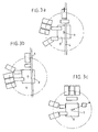
- FIGS. 3a, 3b and 3c are diagrammatic representations in plan of the different phases of movement of the tool-holder modules, in particular during a change in activation of the tool.
- Figure 4 is a schematic representation relating to the principle of implementation of the tool holder modules according to the invention, of which Figure 5 is a representation of an example of a wiring system, and Figure 6 is a top view in Figure 5.
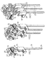
- Figures 7, 8 and 9 are respectively schematic perspective representations of the tool holder module according to the invention, respectively alone and associated with two modules of the same nature, according to two different views.
- Figures 10 and 11 are schematic representations of the operation of the slack cable used at said module according to the invention.
- FIG. 1 a partial sectional view of the installation according to the invention. Basically, it consists of an overhead crane (1), likely to move in translation on a raceway (5) above a electrolysis cell (2), and more precisely from a series of substantially identical cells to each other within which a molten electrolysis bath is maintained, containing in a known manner cryolite and alumina.
- the temperature of the bath is greater than 800 ° C., said bath being subjected to a voltage of about 4.5 volts, the intensity of the direct electric current flowing inside of it typically being of the order of 180,000 to 200,000 amperes.
- this traveling crane (1) receives a carriage (6) capable of moving over a raceway (7) perpendicular to the translation of the crane.
- This cart (6) receives a platform (8), surmounting a vertical central shaft (9), at the level of which is mounted a succession of coaxial crowns one above the other, respectively (10), (11) and (12).
- Each of these crowns has an extension, located substantially in the same plan, and at the level of which is fixed one or more modules (13, 14, 15) of the type described below.
- the maximum angle between the two extreme tools is less than 120 °.
- these angles can be defined according to the characteristics existing facilities, without causing any modification thereof.
- Each of the crowns is equipped with a means of controlling the angle of rotation of the tool or the tool holder that it carries, the angle being determined from a fixed point on the support shaft of said crowns.
- an encoder mounted on the motor shaft of the gear motor for driving the crown in question indicates the angle of rotation of the tool holder from a signal given by a fixed limit switch in rotation.
- an anti-collision system, proximity sensor type, mounted on each tool is associated with the fixed limit switch in rotation, ensuring the relative angular control of the tools.
- the platform (8) receives an upper cabin (not shown), intended to receive the user, the latter being likely to actuate the tools there considered and the corresponding tool holders while monitoring the operation.
- the shaft (9) can also receive a number of coaxial rings additional, likely to carry other tools than those mentioned previously, and in particular a tool for opening the covers (3) of the tanks (2) by example, brushes, etc ...
- the pricking tool is folded towards the left in the direction of the lifting tool, and the tool carrying the shovel is rotated by 270 °, until reaching the level of the tank considered (figure 3b).
- the carriage (6) is first moved on the crane in order to spread the shaft (9), and starting from the tool-holder modules of the piping (4), then the rotation of the tool considered is carried out by taking care before reassembling the tool carriage (25) at its maximum travel on the stiffening mast (23), described below in more detail., When the rotation of said tool is complete, the carriage (6) is returned to its position original.
- each of the tool holder modules and in particular the anode changing modules, have two activation systems independent. They firstly comprise a system of cables (13), wound on one or more two drums (14), the latter being driven in rotation by means of an electric motor (15), via a wheel reducer (16) and worm (17), each wheel (16) being integral and coaxial with one of the drums (14) and coming to cooperate with the screw (17) collinear with the motor shaft of the motor (15). These drums are positioned at level of the upper chassis of each module.
- the cable or cables (13) are wound on two pulleys constituting a hauling system (18) and go up towards a fixed point (19).
- the load and in particular the tool holder considered, is fixed at the level of hauling by any suitable means, itself being secured to a carriage (25), as described in more detail detail below.
- the fixed point (19) is itself secured to the end of the screw (20) a mechanical jack (21), driven by an electric motor (22).
- this double lifting system makes it possible to implement a conventional lifting ensuring the displacement travel of the anodes over relatively large distances at a relatively high speed for a reduced load, and lifting with lifting, likely to develop a significant effort on a reduced race with speed limited.
- This device allows by its traction capacity, on the one hand to develop the effort necessary to tear off the used anode, intended to be replaced, but moreover, given the corresponding low speed, it makes it easier to set up the new anode at the level of the tank.
- the organs of the kinematic chain, and in particular the wheels (16), the drums (14) and the cables (13) are dimensioned as a function of the intense force exerted by said second organ, and to which they are subject, taking into account their solicitation during the phase tear.
- each of the tool holder modules is provided with two drums (14) synchronized by design of the reducer, and each receiving two cables (13), so that the total number of cables is four, as shown in particular in the figures 10 and 11, for example.
- the total number of cables is four, as shown in particular in the figures 10 and 11, for example.
- the tool holder modules are associated change of anodes by three, as shown in Figures 8 and 9.
- This configuration is intended to allow the simultaneous change of three spent anodes. he it is of course nevertheless that each of the modules is likely to function independently of each other, so that, notwithstanding the implementation of a system with three modules, only one or two of them can be activated for the change of anodes.
- the distance between the three tool-holder modules corresponds to the distance between the anodes. This spacing is likely to be different depending on the installation concerned and is therefore adjustable. It is determined by rods, the length of which corresponds to said center distance. This arrangement allows the system to be adapted to any type of installation.
- each tool holder module is associated a vertical guide mast (23), secured to the level of the upper chassis of the module by through a pre-stress device incorporating ball joints, thus susceptible to allow a certain degree of freedom at the level of the lower part (24) of the mast.
- This mast (23) is intended to allow guiding, in particular of a carriage (25) containing the hauling (18) and by extension of the load suspension zone, this carriage (25) being provided with rollers (26) bearing on either side of said mast (23).
- This mast is semi-rigid.
- the threshold for adjusting the pre-stress is such that we are notably freed from risks of angular movement of said tool holder, in particular at the end of travel, in the event of limited efforts, and in particular those inherent in the intense magnetic field that prevails in the installation, and to which the metallic elements constituting a most of the elements used in the construction of the module
- each module comprises a system of slack, thus limiting the vertical travel of the tool when it comes to interact with an obstacle, such as when the shovel comes into contact the bottom of the tank.
- an obstacle such as when the shovel comes into contact the bottom of the tank.
- the slack in the cable allows keep the turns of cables perfectly organized on the drums (14).
- This slack cable is more particularly described in connection with Figures 10 and 11.
- Sa implementation is obtained by securing in a non-fixed manner, the hauling (18) to the carriage (25) for moving the tool holder on the mast (23) by means of a set of two connecting rods (27, 28), capable of moving according to a deformable parallelogram, and articulated respectively on the frame (29) at which the haulage is mounted, and on said carriage (25), between two extreme positions, corresponding to the take-up stroke slack in the cable represented by the double arrow A in FIG. 10.
- FIG. 10 represents the carriage (25) bearing on an object or an obstacle surrounding, the frame (29) no longer being in contact with said carriage (25).
- a sensor no shown, positioned between the carriage (25) and the frame (29) will have given the order to stop the lifting motor while it was making a downward movement.
- the stopping distance maximum mobile hauling is represented by the double arrow A.
- Figure 11 shows the carriage (25) suspended without contact with the environment, the frame (29) which carries the hauling pulleys being in contact with the carriage (25).
- a spring can be put in place between the upper face of the frame (29) and the carriage (25), in order to reduce the apparent weight of said carriage on an object surrounding, allowing in this hypothesis, to preserve the electrolysis tank and its environment.
- the tool holder module according to the invention is dimensioned to accept efforts to the neighboring load of 10 tonnes for speeds of the order of one millimeter per second. On the other hand, for speeds of the order of 15 meters per minute and longer runs significant, the displacement effort is of the order of 2 tonnes.
Landscapes
- Engineering & Computer Science (AREA)
- Mechanical Engineering (AREA)
- Electrolytic Production Of Metals (AREA)
- Analysing Materials By The Use Of Radiation (AREA)
Description

On a décrit dans le document US-A-5 816 565 un système de levage mettant en oeuvre deux organes de levage interagissant entre eux.
En revanche, quelle que soit la qualité de l'huile mise en oeuvre au niveau de ces vérins hydrauliques, compte tenu de la température élevée du bain de fusion, le risque d'incendie est permanent et, on souhaite s'affranchir de cet inconvénient rédhibitoire.
Les solutions proposées jusqu'alors pour éviter l'utilisation du système d'extraction hydraulique se heurtent à un problème d'encombrement et au génie civil des installations existantes. En effet, ces solutions, mettant typiquement en oeuvre un système à câble, demandent un encombrement largement supérieur, incompatible avec ces installations ou, nécessitant la réalisation de nouvelles installations, grevant de manière trop significative les coûts correspondants avant d'être susceptibles d'être amorties.
L'objet de l'invention est donc de proposer une installation pour le changement d'anodes usées au sein d'une série de cuves d'électrolyse, s'affranchissant de ces inconvénients, et notamment compatible avec les usines existantes et s'affranchissant des risques inhérents à la mise en oeuvre de dispositifs hydrauliques. Elle concerne en premier lieu un module porte-outil, destiné notamment à recevoir un outil pour permettre l'arrachage et le transfert des anodes usées. Ce porte-outil peut également intégrer tout type d'outil, et notamment un dispositif apte à rompre la croûte supérieure qui se forme à la surface du bain, mais également d'une pelle ou similaire, destinée à collecter les morceaux de croûte issus de cette rupture.
Ce module porte-outil, destiné à être mis en oeuvre au sein d'une installation de levage, est caractérisé en ce qu'il est muni de deux organes de levage motorisés de manière indépendante :
- un premier organe, constitué d'un système de levage comprenant au moins un câble, un ou deux tambours motorisés électriquement, un mouflage au niveau duquel est fixé un porte-outil, ledit ou lesdits câbles venant s'enrouler sur ledit ou lesdits tambours(s), et étant renvoyé(s) au niveau du mouflage, ledit premier organe de levage étant destiné à assurer le déplacement d'une charge au niveau du mouflage à vitesse relativement importante et selon une course étendue ;
- un second organe, dont l'un des éléments constitutifs est solidarisé à l'extrémité du ou des câbles dudit premier organe après renvoi au niveau du mouflage et comprenant des moyens permettant d'assurer en coopération avec ledit mouflage le déplacement vertical à vitesse réduite et selon une course limitée d'une charge plus importante.
- à permettre de rompre la croûte superficielle qui se créée à la surface supérieure du bain d'électrolyse de chacune des cuves ;
- à collecter tout ou partie des morceaux provenant de la rupture de ladite croûte ;
- et à extraire et transférer les anodes usées hors des cuves et acheminer au niveau desdites cuves des anodes neuves,
La figure 1 est une représentation schématique en section partielle d'une installation conforme à l'invention.
La figure 2 est une représentation analogue à la figure 1, mais selon une vue perpendiculaire par rapport à la vue de la figure 1.
La figure 4 est une représentation schématique relative au principe de mise en oeuvre des modules porte-outils conformes à l'invention, dont la figure 5 est une représentation d'un exemple de système de câblage, et la figure 6 est une vue du dessus de la figure 5.
Les figures 7, 8 et 9 sont respectivement des représentations schématiques en perspective du module porte-outils conforme à l'invention, respectivement seul et associé avec deux modules de même nature, selon deux vues différentes.
Les figures 10 et 11 sont des représentations schématiques du fonctionnement du mou de câble mis en oeuvre au niveau dudit module conforme à l'invention.
- un outil d'acheminement d'anodes neuves, et d'arrachage et d'évacuation des anodes usées ;
- un outil de rupture de la croûte supérieure des bains d'électrolyse ;
- un outil de collecte, typiquement une pelle, de tout ou partie des morceaux issus de la rupture de la croûte.
Claims (15)
- Module porte-outil destiné à être mis en oeuvre au sein d'une installation de levage, comprenant deux organes de levage motorisés de manière indépendante :un premier organe, constitué d'un système de levage comprenant au moins un câble (13), un ou deux tambours (14) motorisés électriquement, un mouflage (18) au niveau duquel est fixé un porte-outil, ledit ou lesdits câbles (13) venant s'enrouler sur ledit ou lesdits tambour(s) (14) et étant renvoyé(s) au niveau du mouflage (18), ledit premier organe de levage étant destiné à assurer le déplacement d'une charge au niveau du mouflage (18) à vitesse relativement importante et selon une course étendue ;un second organe, dont l'un des éléments constitutifs est solidarisé à l'extrémité du ou des câbles (13) dudit premier organe après renvoi au niveau du mouflage (18), et comprenant des moyens permettant d'assurer en coopération avec ledit mouflage le déplacement vertical à vitesse réduite et selon une course limitée d'une charge plus importante.
- Module porte-outil selon la revendication 1, destiné à réaliser l'arrachage d'anodes usées au sein d'une installation de production d'aluminium par électrolyse et le transfert desdites anodes et des anodes neuves venant en remplacement de ces dernières, caractérisé en ce que :le premier organe est destiné à assurer le déplacement d'une anode à vitesse relativement importante et selon une course étendue ;le second organe est destiné à assurer l'arrachage de ladite anode selon une vitesse réduite et pour une course limitée.
- Module porte-outil selon l'une des revendications 1 et 2, caractérisé en ce que ledit second organe est constitué d'un vérin mécanique ou électro-mécanique (20, 21), à l'extrémité duquel sont fixés le ou les câbles (13) dudit premier organe, et destiné à exercer l'effort intense ou d'arrachage.
- Module porte-outil selon l'une des revendications 1 à 3, caractérisé en ce qu'il est muni d'un mou de câble, destiné à limiter la charge appliquée par l'outil, dont est muni ledit module, sur un obstacle, et en particulier au fond d'une cuve à électrolyse.
- Module porte-outil selon l'une des revendications 1 à 4, caractérisé en ce qu'il comporte un mât (23) de guidage vertical semi-rigide, solidarisé au châssis dudit module, et le long duquel est susceptible de coulisser un chariot (25) au niveau duquel est solidarisé le porte-outil proprement dit.
- Module porte-outil selon la revendication 5, caractérisé en ce que le mât de guidage (23) est solidarisé au niveau du châssis du module par l'intermédiaire d'un dispositif de pré-contrainte, destiné à autoriser un certain degré de liberté au niveau de la partie inférieure (24) du mât.
- Module porte-outil selon l'une des revendications 1 à 6, caractérisé en ce que la motorisation des tambours (14) est assurée par au moins un moteur électrique (15), couplé au tambours (14) par le biais d'un réducteur à roue (16) et à vis (17), chaque roue (16) étant solidaire et coaxiale à l'un des tambours (14) et venant coopérer avec la vis (17) colinéaire avec l'arbre moteur du moteur (15).
- Module porte-outil selon la revendication 7, caractérisé en ce que les organes de la chaíne cinématique, et notamment les roues (16), les tambours (14) et les câbles (13), sont dimensionnés en fonction de l'effort intense exercé par ledit second organe (20, 21), et auquel ils sont soumis, compte tenu de leur sollicitation pendant la phase d'arrachage.
- Installation pour le changement des anodes usées au sein d'une usine de production d'aluminium par électrolyse ignée, comprenant un pont roulant (5) susceptible de se déplacer au dessus des cuves d'électrolyse (1), et sur lequel se déplace selon une direction perpendiculaire à la translation du pont un chariot (6) muni d'un module porte-outils conforme à l'une quelconque des revendications 2 à 8, caractérisée en ce que le chariot (6) comporte un arbre vertical (9) recevant une pluralité de couronnes coaxiales (10, 11, 12), susceptibles d'être mues en rotation indépendamment les unes des autres, chacune desdites couronnes recevant un ou plusieurs modules porte-outils, respectivement destinés :lesdits modules porte-outils, et en conséquence, les outils qu'ils portent étant susceptibles de décrire des portions d'arc de cercle.à permettre de rompre la croûte superficielle qui se créée à la surface supérieure du bain d'électrolyse de chacune des cuves ;à collecter tout ou partie des morceaux provenant de la rupture de ladite croûte ;et à extraire et transférer les anodes usées hors des cuves et à acheminer au niveau desdites cuves des anodes neuves
- Installation pour le changement des anodes usées selon la revendication 9, caractérisée en ce que le chariot (6) est surmonté d'une plate-forme (8), destinée à recevoir une cabine supérieure, elle-même destinée à recevoir l'utilisateur, ce dernier étant susceptible d'y actionner les outils et les porte-outils correspondants tout en surveillant la manoeuvre.
- Installation pour le changement des anodes usées selon la revendication 10, caractérisée en ce que la valeur maximale de l'angle séparant deux outils ou porte-outils extrêmes est inférieure à l'encombrement généré par la cabine.
- Installation pour le changement des anodes usées selon la revendication 9, caractérisée en ce que l'angle séparant deux outils ou porte-outils extrêmes est inférieur à 180°.
- Installation pour le changement des anodes usées selon l'une des revendications 9 à 12, caractérisée en ce que chacune des couronnes coaxiales (10 - 12) présente un prolongement, situé sensiblement dans le même plan, et au niveau duquel est fixé un ou plusieurs modules porte-outils (13, 14, 15).
- Installation pour le changement des anodes usées selon l'une des revendications 9 à 13, caractérisée en ce que l'une des couronnes (10) comporte un pluralité de modules porte-outils, montés parallèlement les uns aux autres, et susceptibles de fonctionner indépendamment les uns des autres.
- Installation pour le changement des anodes usées selon la revendication 14, caractérisée en ce que l'écartement entre les modules porte-outil est réglable et correspond à l'entraxe des anodes, ledit écartement étant déterminé par des biellettes, dont la longueur correspond audit entraxe.
Priority Applications (8)
| Application Number | Priority Date | Filing Date | Title |
|---|---|---|---|
| SI9930317T SI1028083T1 (en) | 1999-02-12 | 1999-02-12 | Hoisting device for the replacement of the anodes in the electrolytic cells for aluminium production |
| DE69909230T DE69909230D1 (de) | 1999-02-12 | 1999-02-12 | Hebevorrichtung zur Ersetzung von Anoden in Elektrolyseöfen für die Aluminium-Herstellung |
| ES99420036T ES2203037T3 (es) | 1999-02-12 | 1999-02-12 | Dispositivo de elevacion para el reemplazo de los anodos en las cubas de electrolisis para la produccion de aluminio. |
| EP99420036A EP1028083B1 (fr) | 1999-02-12 | 1999-02-12 | Dispositif de levage pour le remplaçement des anodes dans les cuves d'électrolyse pour la production d'aluminium |
| CA002262065A CA2262065C (fr) | 1999-02-12 | 1999-02-16 | Module porte-outil(s) pour l'extraction et le transfert des anodes au sein d'une usine de fabrication d'aluminium et installation mettant en oeuvre un tel module |
| NO19990725A NO320576B1 (no) | 1999-02-12 | 1999-02-16 | Verktoyholdermodul til uttrekking og overforing av anoder ved et aluminiumsverk, og en installasjon med en slik modul |
| AU15289/00A AU761871B2 (en) | 1999-02-12 | 2000-02-10 | Tool holding device for the extraction and transfer of anodes in the center of an aluminium factory and equipment to put into operation such a device |
| NZ502823A NZ502823A (en) | 1999-02-12 | 2000-02-11 | Anode changing crane for aluminium smelting with tool holders on coaxial annuli rotatable about arcs of circles |
Applications Claiming Priority (3)
| Application Number | Priority Date | Filing Date | Title |
|---|---|---|---|
| EP99420036A EP1028083B1 (fr) | 1999-02-12 | 1999-02-12 | Dispositif de levage pour le remplaçement des anodes dans les cuves d'électrolyse pour la production d'aluminium |
| CA002262065A CA2262065C (fr) | 1999-02-12 | 1999-02-16 | Module porte-outil(s) pour l'extraction et le transfert des anodes au sein d'une usine de fabrication d'aluminium et installation mettant en oeuvre un tel module |
| NO19990725A NO320576B1 (no) | 1999-02-12 | 1999-02-16 | Verktoyholdermodul til uttrekking og overforing av anoder ved et aluminiumsverk, og en installasjon med en slik modul |
Publications (2)
| Publication Number | Publication Date |
|---|---|
| EP1028083A1 EP1028083A1 (fr) | 2000-08-16 |
| EP1028083B1 true EP1028083B1 (fr) | 2003-07-02 |
Family
ID=32073603
Family Applications (1)
| Application Number | Title | Priority Date | Filing Date |
|---|---|---|---|
| EP99420036A Expired - Lifetime EP1028083B1 (fr) | 1999-02-12 | 1999-02-12 | Dispositif de levage pour le remplaçement des anodes dans les cuves d'électrolyse pour la production d'aluminium |
Country Status (7)
| Country | Link |
|---|---|
| EP (1) | EP1028083B1 (fr) |
| AU (1) | AU761871B2 (fr) |
| CA (1) | CA2262065C (fr) |
| DE (1) | DE69909230D1 (fr) |
| NO (1) | NO320576B1 (fr) |
| NZ (1) | NZ502823A (fr) |
| SI (1) | SI1028083T1 (fr) |
Families Citing this family (2)
| Publication number | Priority date | Publication date | Assignee | Title |
|---|---|---|---|---|
| FR2842216B1 (fr) * | 2002-07-11 | 2005-02-25 | Pechiney Aluminium | Installation de production d'aluminium par electrolyse ignee |
| CN101823666B (zh) * | 2009-03-04 | 2014-03-26 | 贵阳铝镁设计研究院有限公司 | 一种铝电解多功能天车工具复位方法及装置 |
Family Cites Families (9)
| Publication number | Priority date | Publication date | Assignee | Title |
|---|---|---|---|---|
| FR660406A (fr) * | 1927-12-30 | 1929-07-11 | Dispositif de secours pour installations de levage commandées par un moteur | |
| US2189447A (en) * | 1936-09-26 | 1940-02-06 | Detroit Hoist And Machine Comp | Hoisting apparatus |
| DE2038942A1 (de) * | 1970-08-05 | 1972-02-10 | Demag Ag | Hebezeug |
| US4664873A (en) * | 1982-05-03 | 1987-05-12 | Deutsche Gesellschaft Fur Wiederaufarbeitung Von Kernbrennstoffen Mbh | System for performing remotely-controlled manual-like operations in large-area cell of a nuclear facility |
| DE3439078A1 (de) * | 1984-10-25 | 1986-04-30 | Klöckner-Humboldt-Deutz AG, 5000 Köln | Verfahren und vorrichtung zur reinigung von losen anodenbruchstuecken |
| FR2615500B1 (fr) * | 1987-05-20 | 1989-07-28 | Reel Sa | Dispositif compensateur de charge pour un engin de manutention et procede pour la mise en oeuvre d'une telle compensation |
| DE4125977A1 (de) * | 1991-08-06 | 1993-02-11 | Heinrich Philippi | Feuerverzinkungsanlage |
| IT1263968B (it) * | 1993-02-25 | 1996-09-05 | Gianfranco Zannini | Apparecchiatura automatizzata per il cambio degli anodi delle celle elettrolitiche per la produzione di alluminio |
| US5816565A (en) * | 1997-02-05 | 1998-10-06 | M Torque, Inc. | Hydraulic blowout preventer lifter |
-
1999
- 1999-02-12 SI SI9930317T patent/SI1028083T1/xx unknown
- 1999-02-12 EP EP99420036A patent/EP1028083B1/fr not_active Expired - Lifetime
- 1999-02-12 DE DE69909230T patent/DE69909230D1/de not_active Expired - Lifetime
- 1999-02-16 NO NO19990725A patent/NO320576B1/no not_active IP Right Cessation
- 1999-02-16 CA CA002262065A patent/CA2262065C/fr not_active Expired - Lifetime
-
2000
- 2000-02-10 AU AU15289/00A patent/AU761871B2/en not_active Ceased
- 2000-02-11 NZ NZ502823A patent/NZ502823A/en not_active IP Right Cessation
Also Published As
| Publication number | Publication date |
|---|---|
| CA2262065A1 (fr) | 2000-08-16 |
| EP1028083A1 (fr) | 2000-08-16 |
| DE69909230D1 (de) | 2003-08-07 |
| NO320576B1 (no) | 2005-12-27 |
| CA2262065C (fr) | 2008-10-21 |
| AU761871B2 (en) | 2003-06-12 |
| SI1028083T1 (en) | 2003-10-31 |
| AU1528900A (en) | 2000-08-17 |
| NO990725L (no) | 2000-08-17 |
| NO990725D0 (no) | 1999-02-16 |
| NZ502823A (en) | 2001-06-29 |
Similar Documents
| Publication | Publication Date | Title |
|---|---|---|
| EP1028084B1 (fr) | Dispositif de levage pour le remplaçement des anodes dans les cuves d'électrolyse pour la production d'aluminium | |
| EP2337880B1 (fr) | Machine de service utilisee pour intervenir sur les cellules d´ lectrolyse de production d'aluminium par electrolyse ignee | |
| EP1849743B1 (fr) | Dispositif compensateur de charge, notamment pour engin de levage | |
| EP2510136B1 (fr) | Dispositif destine a collecter des debris solides dans une cuve d'electrolyse destinee a la production d'aluminium | |
| EP1028083B1 (fr) | Dispositif de levage pour le remplaçement des anodes dans les cuves d'électrolyse pour la production d'aluminium | |
| EP2430215B1 (fr) | Dispositif pour collecter les debris solides presents dans le bain et le metal liquide d'une cuve d lectrolyse destinee a la production d'aluminium, par raclage du fond de ladite cuve | |
| CA2596054C (fr) | Module porte outil(s) pour l'extraction et le transfert des anodes au sein d'une usine de fabrication d'aluminium et installation mettant en oeuvre un tel module | |
| EP1101726B1 (fr) | Unité de levage et de manutention de charges au sein d'une installation de production d'aluminium | |
| FR2474536A1 (fr) | Cellule d'electrolyse comportant un montage d'anode particulier, et procede d'electrolyse utilisant cette cellule pour la production d'aluminium | |
| CA2560675C (fr) | Module de service compact destine aux usines de production d'aluminium par electrolyse | |
| WO2020181379A1 (fr) | Outil d'intervention pour l'exploitation d'une cuve d'electrolyse | |
| CA2938716C (fr) | Systeme pour la realisation d'operations liees a l'exploitation de cellules d'une installation de production d'aluminium par electrolyse | |
| EP1443128B1 (fr) | Machine de service de cellules d'électrolyse pour la production d'aluminium | |
| WO2016128652A1 (fr) | Procédé pour désengager un ensemble anodique usé d'une cuve d'une installation de production d'aluminium | |
| FR2701278A1 (fr) | Procédé de curage et dispositif de curage et d'inspection de collecteurs d'égouts. | |
| WO2020181380A1 (fr) | Dispositif de manutention destine a convoyer un outil d'intervention sur une cuve d'electrolyse | |
| EP1101838B1 (fr) | Méthode de gestion du fonctionnement d'une installation de production d'aluminium par électrolyse ignée et installation de production d'aluminium mettant en oeuvre cette méthode | |
| CA3131450C (fr) | Outil d'intervention pour l'exploitation d'une cuve d'electrolyse | |
| CA2639893A1 (fr) | Module de service pilotable a distance destine aux usines de production d'aluminium |
Legal Events
| Date | Code | Title | Description |
|---|---|---|---|
| PUAI | Public reference made under article 153(3) epc to a published international application that has entered the european phase |
Free format text: ORIGINAL CODE: 0009012 |
|
| AK | Designated contracting states |
Kind code of ref document: A1 Designated state(s): DE ES FR GB GR IT NL SE |
|
| AX | Request for extension of the european patent |
Free format text: AL;LT;LV;MK;RO;SI |
|
| 17P | Request for examination filed |
Effective date: 20010109 |
|
| AKX | Designation fees paid |
Free format text: DE ES FR GB GR IT NL SE |
|
| AXX | Extension fees paid |
Free format text: MK PAYMENT 20010109;RO PAYMENT 20010109;SI PAYMENT 20010109 |
|
| 17Q | First examination report despatched |
Effective date: 20020722 |
|
| GRAH | Despatch of communication of intention to grant a patent |
Free format text: ORIGINAL CODE: EPIDOS IGRA |
|
| GRAH | Despatch of communication of intention to grant a patent |
Free format text: ORIGINAL CODE: EPIDOS IGRA |
|
| GRAA | (expected) grant |
Free format text: ORIGINAL CODE: 0009210 |
|
| AK | Designated contracting states |
Designated state(s): DE ES FR GB GR IT NL SE |
|
| AX | Request for extension of the european patent |
Extension state: MK RO SI |
|
| PG25 | Lapsed in a contracting state [announced via postgrant information from national office to epo] |
Ref country code: NL Free format text: LAPSE BECAUSE OF FAILURE TO SUBMIT A TRANSLATION OF THE DESCRIPTION OR TO PAY THE FEE WITHIN THE PRESCRIBED TIME-LIMIT Effective date: 20030702 |
|
| REG | Reference to a national code |
Ref country code: GB Ref legal event code: FG4D Free format text: NOT ENGLISH |
|
| REF | Corresponds to: |
Ref document number: 69909230 Country of ref document: DE Date of ref document: 20030807 Kind code of ref document: P |
|
| PG25 | Lapsed in a contracting state [announced via postgrant information from national office to epo] |
Ref country code: SE Free format text: LAPSE BECAUSE OF FAILURE TO SUBMIT A TRANSLATION OF THE DESCRIPTION OR TO PAY THE FEE WITHIN THE PRESCRIBED TIME-LIMIT Effective date: 20031002 Ref country code: GR Free format text: LAPSE BECAUSE OF FAILURE TO SUBMIT A TRANSLATION OF THE DESCRIPTION OR TO PAY THE FEE WITHIN THE PRESCRIBED TIME-LIMIT Effective date: 20031002 |
|
| PG25 | Lapsed in a contracting state [announced via postgrant information from national office to epo] |
Ref country code: DE Free format text: LAPSE BECAUSE OF FAILURE TO SUBMIT A TRANSLATION OF THE DESCRIPTION OR TO PAY THE FEE WITHIN THE PRESCRIBED TIME-LIMIT Effective date: 20031003 |
|
| GBT | Gb: translation of ep patent filed (gb section 77(6)(a)/1977) | ||
| NLV1 | Nl: lapsed or annulled due to failure to fulfill the requirements of art. 29p and 29m of the patents act | ||
| REG | Reference to a national code |
Ref country code: ES Ref legal event code: FG2A Ref document number: 2203037 Country of ref document: ES Kind code of ref document: T3 |
|
| PLBE | No opposition filed within time limit |
Free format text: ORIGINAL CODE: 0009261 |
|
| STAA | Information on the status of an ep patent application or granted ep patent |
Free format text: STATUS: NO OPPOSITION FILED WITHIN TIME LIMIT |
|
| 26N | No opposition filed |
Effective date: 20040405 |
|
| REG | Reference to a national code |
Ref country code: SI Ref legal event code: IF |
|
| REG | Reference to a national code |
Ref country code: FR Ref legal event code: PLFP Year of fee payment: 18 |
|
| PGFP | Annual fee paid to national office [announced via postgrant information from national office to epo] |
Ref country code: IT Payment date: 20160212 Year of fee payment: 18 Ref country code: ES Payment date: 20160301 Year of fee payment: 18 |
|
| PGFP | Annual fee paid to national office [announced via postgrant information from national office to epo] |
Ref country code: GB Payment date: 20160216 Year of fee payment: 18 |
|
| REG | Reference to a national code |
Ref country code: FR Ref legal event code: PLFP Year of fee payment: 19 |
|
| GBPC | Gb: european patent ceased through non-payment of renewal fee |
Effective date: 20170212 |
|
| REG | Reference to a national code |
Ref country code: SI Ref legal event code: KO00 Effective date: 20171208 |
|
| REG | Reference to a national code |
Ref country code: FR Ref legal event code: PLFP Year of fee payment: 20 |
|
| PG25 | Lapsed in a contracting state [announced via postgrant information from national office to epo] |
Ref country code: GB Free format text: LAPSE BECAUSE OF NON-PAYMENT OF DUE FEES Effective date: 20170212 Ref country code: IT Free format text: LAPSE BECAUSE OF NON-PAYMENT OF DUE FEES Effective date: 20170212 |
|
| PGFP | Annual fee paid to national office [announced via postgrant information from national office to epo] |
Ref country code: FR Payment date: 20180226 Year of fee payment: 20 |
|
| REG | Reference to a national code |
Ref country code: ES Ref legal event code: FD2A Effective date: 20180626 |
|
| PG25 | Lapsed in a contracting state [announced via postgrant information from national office to epo] |
Ref country code: ES Free format text: LAPSE BECAUSE OF NON-PAYMENT OF DUE FEES Effective date: 20170213 |