EP1028084B1 - Dispositif de levage pour le remplaçement des anodes dans les cuves d'électrolyse pour la production d'aluminium - Google Patents
Dispositif de levage pour le remplaçement des anodes dans les cuves d'électrolyse pour la production d'aluminium Download PDFInfo
- Publication number
- EP1028084B1 EP1028084B1 EP99420037A EP99420037A EP1028084B1 EP 1028084 B1 EP1028084 B1 EP 1028084B1 EP 99420037 A EP99420037 A EP 99420037A EP 99420037 A EP99420037 A EP 99420037A EP 1028084 B1 EP1028084 B1 EP 1028084B1
- Authority
- EP
- European Patent Office
- Prior art keywords
- tool holder
- anodes
- intended
- carriage
- module according
- Prior art date
- Legal status (The legal status is an assumption and is not a legal conclusion. Google has not performed a legal analysis and makes no representation as to the accuracy of the status listed.)
- Expired - Lifetime
Links
- 229910052782 aluminium Inorganic materials 0.000 title claims description 9
- XAGFODPZIPBFFR-UHFFFAOYSA-N aluminium Chemical compound [Al] XAGFODPZIPBFFR-UHFFFAOYSA-N 0.000 title claims description 9
- 239000004411 aluminium Substances 0.000 title claims 3
- 238000004519 manufacturing process Methods 0.000 title description 6
- 238000009434 installation Methods 0.000 claims description 24
- 238000005868 electrolysis reaction Methods 0.000 claims description 21
- 239000000470 constituent Substances 0.000 claims description 2
- 230000008859 change Effects 0.000 description 5
- 239000003638 chemical reducing agent Substances 0.000 description 5
- PNEYBMLMFCGWSK-UHFFFAOYSA-N aluminium oxide Inorganic materials [O-2].[O-2].[O-2].[Al+3].[Al+3] PNEYBMLMFCGWSK-UHFFFAOYSA-N 0.000 description 4
- 229910001610 cryolite Inorganic materials 0.000 description 4
- 238000006073 displacement reaction Methods 0.000 description 4
- 210000000056 organ Anatomy 0.000 description 4
- OKTJSMMVPCPJKN-UHFFFAOYSA-N Carbon Chemical compound [C] OKTJSMMVPCPJKN-UHFFFAOYSA-N 0.000 description 3
- 229910052799 carbon Inorganic materials 0.000 description 3
- 238000006243 chemical reaction Methods 0.000 description 3
- 238000000605 extraction Methods 0.000 description 3
- 238000000034 method Methods 0.000 description 3
- 230000008569 process Effects 0.000 description 3
- 238000012546 transfer Methods 0.000 description 3
- 101000852483 Homo sapiens Interleukin-1 receptor-associated kinase 1 Proteins 0.000 description 2
- 102100036342 Interleukin-1 receptor-associated kinase 1 Human genes 0.000 description 2
- 241001417494 Sciaenidae Species 0.000 description 2
- 230000008901 benefit Effects 0.000 description 2
- 229910018072 Al 2 O 3 Inorganic materials 0.000 description 1
- UGFAIRIUMAVXCW-UHFFFAOYSA-N Carbon monoxide Chemical compound [O+]#[C-] UGFAIRIUMAVXCW-UHFFFAOYSA-N 0.000 description 1
- 241000861223 Issus Species 0.000 description 1
- 230000004913 activation Effects 0.000 description 1
- 230000000295 complement effect Effects 0.000 description 1
- 238000010276 construction Methods 0.000 description 1
- 238000013461 design Methods 0.000 description 1
- 238000011161 development Methods 0.000 description 1
- 238000007599 discharging Methods 0.000 description 1
- 230000005611 electricity Effects 0.000 description 1
- 239000007789 gas Substances 0.000 description 1
- 230000010354 integration Effects 0.000 description 1
- 239000000155 melt Substances 0.000 description 1
- 229910052751 metal Inorganic materials 0.000 description 1
- 239000000203 mixture Substances 0.000 description 1
- 238000011084 recovery Methods 0.000 description 1
- 238000000926 separation method Methods 0.000 description 1
- 239000000725 suspension Substances 0.000 description 1
- 230000001360 synchronised effect Effects 0.000 description 1
- 238000013519 translation Methods 0.000 description 1
Images




Classifications
-
- B—PERFORMING OPERATIONS; TRANSPORTING
- B66—HOISTING; LIFTING; HAULING
- B66C—CRANES; LOAD-ENGAGING ELEMENTS OR DEVICES FOR CRANES, CAPSTANS, WINCHES, OR TACKLES
- B66C17/00—Overhead travelling cranes comprising one or more substantially horizontal girders the ends of which are directly supported by wheels or rollers running on tracks carried by spaced supports
-
- B—PERFORMING OPERATIONS; TRANSPORTING
- B66—HOISTING; LIFTING; HAULING
- B66D—CAPSTANS; WINCHES; TACKLES, e.g. PULLEY BLOCKS; HOISTS
- B66D3/00—Portable or mobile lifting or hauling appliances
- B66D3/04—Pulley blocks or like devices in which force is applied to a rope, cable, or chain which passes over one or more pulleys, e.g. to obtain mechanical advantage
-
- B—PERFORMING OPERATIONS; TRANSPORTING
- B66—HOISTING; LIFTING; HAULING
- B66D—CAPSTANS; WINCHES; TACKLES, e.g. PULLEY BLOCKS; HOISTS
- B66D3/00—Portable or mobile lifting or hauling appliances
- B66D3/18—Power-operated hoists
-
- C—CHEMISTRY; METALLURGY
- C07—ORGANIC CHEMISTRY
- C07C—ACYCLIC OR CARBOCYCLIC COMPOUNDS
- C07C219/00—Compounds containing amino and esterified hydroxy groups bound to the same carbon skeleton
- C07C219/02—Compounds containing amino and esterified hydroxy groups bound to the same carbon skeleton having esterified hydroxy groups and amino groups bound to acyclic carbon atoms of the same carbon skeleton
- C07C219/04—Compounds containing amino and esterified hydroxy groups bound to the same carbon skeleton having esterified hydroxy groups and amino groups bound to acyclic carbon atoms of the same carbon skeleton the carbon skeleton being acyclic and saturated
- C07C219/06—Compounds containing amino and esterified hydroxy groups bound to the same carbon skeleton having esterified hydroxy groups and amino groups bound to acyclic carbon atoms of the same carbon skeleton the carbon skeleton being acyclic and saturated having the hydroxy groups esterified by carboxylic acids having the esterifying carboxyl groups bound to hydrogen atoms or to acyclic carbon atoms of an acyclic saturated carbon skeleton
-
- C—CHEMISTRY; METALLURGY
- C25—ELECTROLYTIC OR ELECTROPHORETIC PROCESSES; APPARATUS THEREFOR
- C25C—PROCESSES FOR THE ELECTROLYTIC PRODUCTION, RECOVERY OR REFINING OF METALS; APPARATUS THEREFOR
- C25C3/00—Electrolytic production, recovery or refining of metals by electrolysis of melts
- C25C3/06—Electrolytic production, recovery or refining of metals by electrolysis of melts of aluminium
- C25C3/08—Cell construction, e.g. bottoms, walls, cathodes
- C25C3/10—External supporting frames or structures
-
- C—CHEMISTRY; METALLURGY
- C25—ELECTROLYTIC OR ELECTROPHORETIC PROCESSES; APPARATUS THEREFOR
- C25C—PROCESSES FOR THE ELECTROLYTIC PRODUCTION, RECOVERY OR REFINING OF METALS; APPARATUS THEREFOR
- C25C3/00—Electrolytic production, recovery or refining of metals by electrolysis of melts
- C25C3/06—Electrolytic production, recovery or refining of metals by electrolysis of melts of aluminium
- C25C3/08—Cell construction, e.g. bottoms, walls, cathodes
- C25C3/12—Anodes
- C25C3/125—Anodes based on carbon
-
- C—CHEMISTRY; METALLURGY
- C25—ELECTROLYTIC OR ELECTROPHORETIC PROCESSES; APPARATUS THEREFOR
- C25C—PROCESSES FOR THE ELECTROLYTIC PRODUCTION, RECOVERY OR REFINING OF METALS; APPARATUS THEREFOR
- C25C3/00—Electrolytic production, recovery or refining of metals by electrolysis of melts
- C25C3/06—Electrolytic production, recovery or refining of metals by electrolysis of melts of aluminium
- C25C3/14—Devices for feeding or crust breaking
Definitions
- the present invention relates generally to the change from spent anodes to within aluminum production electrolysis tanks. It concerns everything particularly a module capable of allowing the actual extraction of worn anodes and the installation using such modules.
- Aluminum is produced industrially by the well-known process today of igneous electrolysis, that is to say using the electrolysis of alumina in a molten cryolite bath according to the reaction: Al 2 O 3 + 2e - + Na 3 [AlF 6 ] ⁇ 2 Al + 3O 2 + 3C ⁇ 3CO 2 + F Alumina cryolite
- This highly exothermic reaction therefore sets up a molten bath comprising a mixture of cryolite and alumina, the temperature of which is generally higher than 800 ° C, and consumes a lot of electricity, so that the installations operate in continuous mode, in order to limit the energy losses inherent in the phases restart.
- the object of the invention is therefore to provide an installation for changing anodes worn in a series of electrolytic cells, overcoming these drawbacks, and particularly compatible with existing factories and free from inherent risks the use of hydraulic devices.
- a module tool holder intended in particular to receive a tool to allow the uprooting and the transfer of spent anodes.
- This tool holder can also integrate any type of tool, and in particular a device capable of breaking the upper crust which forms on the surface of the bath, but also a shovel or similar, intended to collect the pieces of crust resulting from this rupture.
- the invention therefore consists, firstly, in differentiating two movements, in know a movement requiring intense effort on a short run at reduced speed, and a movement requiring significantly less effort on a much longer run long, also at a much higher speed.
- this module is particularly suitable for uprooting and transfer of spent anodes.
- the second organ is intended to allow the setting in work of an intense traction effort, necessary and sufficient to allow the uprooting proper of the spent anode outside the electrolysis bath, while the first organ, after effective removal of said anode, ensures the displacement thereof outside the tank.
- the first member consists of a cable lifting system, carrying one or more cables wound on one or more several drums driven by an electric motor, and fitted with a hauling system level of which is fixed a tool, for example for gripping the anode, for breaking the upper crust of the electrolysis bath or of a tool acting as a shovel recovery of pieces from said layer.
- said second member consists of a mechanical or electro-mechanical jack, at the end of which are fixed the cable or cables of said first member.
- the invention consists in making a system for lifting a load provided with a fixed point, said fixed point being capable of being made mobile over a race limited by means of said second member, that is to say in the present case, of a jack mechanical or electro-mechanical.
- the module is provided with a cable slack, so as to limit the load applied by the tool, with which said module is provided, on an obstacle, and in particular in bottom of electrolytic cell.
- this slack in the cable makes it possible to maintain the turns of cables perfectly wound at the level of the drum (s), and is also designed not to not apply any effort to the level of the installation plan, as specified in a more detailed manner detailed later.
- the tool holder module comprises a mast semi-rigid vertical guide, secured to the chassis of said module, and along which slides a tool carriage itself.
- the invention also relates to the installation for changing spent anodes of aluminum production electrolysis tanks.
- This installation includes an overhead crane capable of moving above said tanks and on which moves in a direction perpendicular to the translation of the bridge at least one trolley fitted with a tool holder module intended to extract and transfer the spent anodes outside the tanks, and to convey new anodes to the said tanks.
- Figure 1 is a schematic perspective representation of part of a factory for aluminum production showing a series of electrolytic cells
- Figure 2 is a schematic perspective representation of the installation according to the invention, and in particular showing the overhead crane provided with three separate carriages.
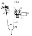
- FIG. 3 is a schematic representation relating to the principle of implementation of tool-holder modules according to the invention
- FIG. 4 of which is a representation of a example of a wiring system
- Figure 5 is a top view of Figure 4.
- Figures 6, 7 and 8 are respectively schematic perspective views of the tool holder module according to the invention, respectively alone and associated with two modules of the same nature, from two different views.
- Figures 9 and 10 are schematic representations of the operation of the slack cable used at said module according to the invention.
- Figure 1 a schematic view of a series of tanks electrolysis (1) for the production of aluminum, according to the so-called electrolysis process igneous, these tanks being installed in a factory likely to include several series of such tanks.
- the installation comprises a plurality of tanks (1), substantially identical to each other, each of the tanks comprising a cover access (2) inside the tank, and in particular to the molten electrolysis bath proper, capable of thus freeing access, in particular to the carbon anodes (3).
- each of the cells is closed and is provided with a device for collecting gaseous effluents in the form of pipes (4), said effluents being generally reprocessed in order to avoid their rejection in the state in the atmosphere.
- the building containing this series of tanks is equipped with a raceway (5), on which is likely to move an overhead crane (6), which is shown more in detail in Figure 2.
- each of these carts is provided with its own drive device in steering, in particular by means of electric motors.
- the two external carriages respectively carrying the crust breaking tools and the shovel are each provided with two raceways, respectively upper and lower, and therefore complementary cooperation, in particular pebbles, capable of enabling them to uniform and guided movement at deck level.
- the carriage (12), fitted with the module carrying the shovel, is then in turn brought into line with said tank by setting in motion the traveling crane (6) and said carriage, so as to allow the introduction of the shovel within it, in order to collect the pieces from from the breaking of the crust. These pieces are evacuated to an appropriate area.
- anode changing carriage (10) is in turn brought into line with the tank, and in particular instead of changing the anodes, and an operator induces the uprooting of the anodes considered and their disposal, also in a storage area defined, and the installation of new anodes.
- each of the tool holder modules and in particular the anode changing modules, have two activation systems independent. They firstly comprise a system of cables (13), wound on one or more two drums (14), the latter being driven in rotation by means of an electric motor (15), via a wheel reducer (16) and worm (17), each wheel (16) being integral and coaxial with one of the drums (14) and coming to cooperate with the screw (17) collinear with the motor shaft of the motor (15). These drums are positioned at level of the upper chassis of each module.
- the cable or cables (13) are wound on two pulleys constituting a hauling system (18) and go up towards a fixed point (19).
- the load and in particular the tool holder considered, is fixed at the level of hauling by any suitable means, itself being secured to a carriage (25), as described in more detail detail below.
- the fixed point (19) is itself secured to the end of the screw (20) a mechanical jack (21), driven by an electric motor (22).
- this double lifting system makes it possible to implement a conventional lifting ensuring the displacement travel of the anodes over relatively large distances at a relatively high speed for a reduced load, and lifting with lifting, likely to develop a significant effort on a reduced race with speed limited.
- This device allows by its traction capacity, on the one hand to ensure the development of the effort required to tear off the spent anode, intended to be replaced, but by elsewhere, given the corresponding low speed, it makes it easier to set up place the new anode at the level of the tank.
- the organs of the kinematic chain, and in particular the wheels (16), the drums (14) and the cables (13) are dimensioned as a function of the intense force exerted by said second organ, and to which they are subject, taking into account their solicitation during the phase tear.
- each of the tool holder modules is provided with two drums (14) synchronized by design of the reducer, and each receiving two cables (13), so that the total number of cables is four, as shown in particular in the figures 9 and 10, for example.
- the total number of cables is four, as shown in particular in the figures 9 and 10, for example.
- the tool holder modules are associated change of anodes by three, as shown in Figures 7 and 8.
- This configuration is intended to allow the simultaneous change of three spent anodes. he is of course, however, that each of the modules is likely to work independently of each other, so that, notwithstanding the implementation of a system with three modules, only one or two of them can be activated for the change of anodes.
- the distance between the three tool-holder modules corresponds to the distance between the anodes. This spacing is likely to be different depending on the installation concerned and is therefore adjustable. It is determined by rods, the length of which corresponds to said center distance. This arrangement allows the system to be adapted to any type of installation.
- each tool holder module is associated a vertical guide mast (23), secured to the level of the upper chassis of the module by through a pre-stress device incorporating ball joints, thus susceptible to allow a certain degree of freedom at the level of the lower part (24) of the mast.
- This mast (23) is intended to allow guiding, in particular of a carriage (25) containing the hauling (18) and by extension of the load suspension zone, this carriage (25) being provided with rollers (26) bearing on either side of said mast (23).
- This mast is semi-rigid.
- the threshold for adjusting the pre-stress is such that we are notably freed from risks of angular movement of said tool holder, in particular at the end of travel, in the event of limited efforts, and in particular those inherent in the intense magnetic field that prevails in the installation, and to which the metallic elements constituting a most of the elements used in the construction of the module
- each module comprises a system of slack, thus limiting the vertical travel of the tool when it comes to interact with an obstacle, such as when the shovel comes into contact the bottom of the tank.
- an obstacle such as when the shovel comes into contact the bottom of the tank.
- the slack in the cable allows keep the turns of cables perfectly organized on the drums (14).
- This slack cable is more particularly described in connection with Figures 9 and 10.
- Sa implementation is obtained by securing in a non-fixed manner, the hauling (18) to the carriage (25) for moving the tool holder on the mast (23) by means of a set of two connecting rods (27, 28), capable of moving according to a deformable parallelogram, and articulated respectively on the frame (29) at which the haulage is mounted, and on said carriage (25), between two extreme positions, corresponding to the take-up stroke slack in the cable represented by the double arrow A in FIG. 9
- FIG. 9 represents the carriage (25) bearing on an object or an obstacle surrounding, the frame (29) no longer being in contact with said carriage (25).
- a sensor no shown, positioned between the carriage (25) and the frame (29) will have given the order to stop the lifting motor while it was making a downward movement.
- the stopping distance maximum mobile hauling is represented by the double arrow A.
- Figure 10 shows the carriage (25) suspended without contact with the environment, the frame (29) which carries the hauling pulleys being in contact with the carriage (25).
- a spring can be put in place between the upper face of the frame (29) and the carriage (25), in order to reduce the apparent weight of said carriage on an object surrounding, allowing in this hypothesis, to preserve the electrolysis tank and its environment.
- the tool holder module according to the invention is dimensioned to accept efforts to the neighboring load of 10 tonnes for speeds of the order of one millimeter per second. On the other hand, for speeds of the order of 15 meters per minute and longer runs significant, the displacement effort is of the order of 2 tonnes.
Landscapes
- Chemical & Material Sciences (AREA)
- Engineering & Computer Science (AREA)
- Organic Chemistry (AREA)
- Mechanical Engineering (AREA)
- Chemical Kinetics & Catalysis (AREA)
- Electrochemistry (AREA)
- Materials Engineering (AREA)
- Metallurgy (AREA)
- Electrolytic Production Of Metals (AREA)
- Analysing Materials By The Use Of Radiation (AREA)
Description
Alumine cryolithe
- un premier organe, constitué d'un système de levage comprenant au moins un câble, un ou deux tambours motorisés électriquement, un mouflage au niveau duquel est fixé un porte-outil, ledit ou lesdits câbles venant s'enrouler sur ledit ou lesdits tambour(s) et étant renvoyé(s) au niveau du mouflage, ledit premier organe de levage étant destiné à assurer le déplacement d'une charge au niveau du mouflage à vitesse relativement importante et selon une course étendue ;
- un second organe, dont l'un des éléments constitutifs est solidarisé à l'extrémité du ou des câbles dudit premier organe après renvoi au niveau du mouflage et comprenant des moyens permettant d'assurer en coopération avec ledit mouflage le déplacement vertical à vitesse réduite et selon une course limitée d'une charge plus importante.
- respectivement un premier chariot comportant un outil destiné à rompre la croûte superficielle qui se créée à la surface supérieure du bain d'électrolyse de chacune des cuves ;
- un second chariot comportant un outil muni d'une pelle, destiné à permettre la collecte de tout ou partie des morceaux provenant de la rupture de ladite croûte ;
- (10) de support de modules d'acheminement des anodes neuves et d'évacuation des anodes usées, se déplaçant sur le chemin de roulement (7);
- (11) de support d'un outil de rupture de la croûte supérieure des bains d'électrolyse, se déplaçant sur le chemin de roulement (8);
- (12) de support d'un outil de collecte, typiquement une pelle, de tout ou partie des morceaux issus de la rupture de la croûte, se déplaçant sur le chemin de roulement (9).
Claims (11)
- Module porte-outil destiné à être mis en oeuvre au sein d'une installation de levage, comprenant deux organes de levage motorisés de manière indépendante :un premier organe, constitué d'un système de levage comprenant au moins un câble (13), un ou deux tambours (14) motorisés électriquement, un mouflage (18) au niveau duquel est fixé un porte-outil, ledit ou lesdits câbles (13) venant s'enrouler sur ledit ou lesdits tambour(s) (14) et étant renvoyé(s) au niveau du mouflage (18), ledit premier organe de levage étant destiné à assurer le déplacement d'une charge au niveau du mouflage (18) à vitesse relativement importante et selon une course étendue ;un second organe, dont l'un des éléments constitutifs est solidarisé à l'extrémité du ou des câbles (13) dudit premier organe après renvoi au niveau du mouflage (18), et comprenant des moyens permettant d'assurer en coopération avec ledit mouflage le déplacement vertical à vitesse réduite et selon une course limitée d'une charge plus importante.
- Module porte-outil selon la revendication 1, destiné à réaliser l'arrachage d'anodes usées au sein d'une installation de production d'aluminium par électrolyse et le transfert desdites anodes et des anodes neuves venant en remplacement de ces dernières, caractérisé en ce que :le premier organe est destiné à assurer le déplacement d'une anode à vitesse relativement importante et selon une course étendue ;le second organe est destiné à assurer l'arrachage de ladite anode selon une vitesse réduite et pour une course limitée.
- Module porte-outil selon l'une des revendications 1 et 2, caractérisé en ce que ledit second organe est constitué d'un vérin mécanique ou électro-mécanique (20, 21), à l'extrémité duquel sont fixés le ou les câbles (13) dudit premier organe, et destiné à exercer l'effort intense ou d'arrachage.
- Module porte-outil selon l'une des revendications 1 à 3, caractérisé en ce qu'il est muni d'un mou de câble, destiné à limiter la charge appliquée par l'outil, dont est muni ledit module, sur un obstacle, et en particulier au fond d'une cuve à électrolyse.
- Module porte-outil selon l'une des revendications 1 à 4, caractérisé en ce qu'il comporte un mât (23) de guidage vertical semi-rigide, solidarisé au châssis dudit module, et le long duquel est susceptible de coulisser un chariot (25) au niveau duquel est solidarisé le porte-outil proprement dit.
- Module porte-outil selon la revendication 5, caractérisé en ce que le mât de guidage (23) est solidarisé au niveau du châssis du module par l'intermédiaire d'un dispositif de pré-contrainte, destiné à autoriser un certain degré de liberté au niveau de la partie inférieure (24) du mât.
- Module porte-outil selon l'une des revendications 1 à 6, caractérisé en ce que la motorisation des tambours (14) est assurée par au moins un moteur électrique (15), couplé au tambours (14) par le biais d'un réducteur à roue (16) et à vis (17), chaque roue (16) étant solidaire et coaxiale à l'un des tambours (14) et venant coopérer avec la vis (17) colinéaire avec l'arbre moteur du moteur (15).
- Module porte-outil selon la revendications 7, caractérisé en ce que les organes de la chaíne cinématique, et notamment les roues (16), les tambours (14) et les câbles (13), sont dimensionnés en fonction de l'effort intense exercé par ledit second organe (20, 21), et auquel ils sont soumis, compte tenu de leur sollicitation pendant la phase d'arrachage.
- Installation pour le changement des anodes usées d'une usine de production d'aluminium par électrolyse ignée, comprenant un pont roulant (5) susceptible de se déplacer au dessus des cuves d'électrolyse (1), et sur lequel se déplace selon une direction perpendiculaire à la translation du pont au moins un chariot (10) muni d'un module porte-outil selon l'une des revendications 2 à 8, destiné à extraire et transférer les anodes usées hors des cuves, et à acheminer au niveau desdites cuves des anodes neuves, caractérisée en ce qu'elle comporte en outre deux autres chariots (11, 12), également susceptibles de se déplacer sur le pont roulant (5) selon une direction perpendiculaire à la translation dudit pont :les trois chariots étant susceptibles de se déplacer de manière indépendante les uns par rapport aux autres.respectivement un premier chariot (11) comportant un outil destiné à permettre de rompre la croûte superficielle qui se créée à la surface supérieure du bain d'électrolyse de chacune des cuves (1);un second chariot (12) comportant un outil muni d'une pelle, destiné à permettre la collecte de tout ou partie des morceaux provenant de la rupture de ladite croûte ;
- Installation pour le changement des anodes usées selon la revendication 9, caractérisée en ce que le chariot (10) est muni d'une pluralité de modules porte-outil, montés parallèlement les uns aux autres, et susceptibles de fonctionner concomitamment ou indépendamment les uns des autres.
- Installation pour le changement des anodes usées selon la revendication 10, caractérisée en ce que l'écartement entre les modules porte-outil est réglable et correspond à l'entraxe des anodes, ledit écartement étant déterminé par des biellettes, dont la longueur correspond audit entraxe.
Priority Applications (10)
| Application Number | Priority Date | Filing Date | Title |
|---|---|---|---|
| DE69909231T DE69909231D1 (de) | 1999-02-12 | 1999-02-12 | Hebevorrichtung zur Ersetzung von Anoden in Elektrolyseöfen für die Aluminium-Herstellung |
| EP99420037A EP1028084B1 (fr) | 1999-02-12 | 1999-02-12 | Dispositif de levage pour le remplaçement des anodes dans les cuves d'électrolyse pour la production d'aluminium |
| SI9930310T SI1028084T1 (en) | 1999-02-12 | 1999-02-12 | Hoisting device for the replacement of the anodes in the electrolytic cells for aluminium production |
| ES99420037T ES2203038T3 (es) | 1999-02-12 | 1999-02-12 | Dispositivo de elevacion para el reemplazo de anodos en las cubas de electrolisis para la produccion de aluminio. |
| US09/250,633 US6153066A (en) | 1999-02-12 | 1999-02-16 | Tool holding device for the extraction and transfer of anodes in the center of an aluminum factory and equipment for operating such |
| CA002262063A CA2262063C (fr) | 1999-02-12 | 1999-02-16 | Module porte-outil(s) pour l'extraction et le transfert des anodes au sein d'une usine de fabrication d'aluminium, et installation mettant en oeuvre un tel module |
| NO19990724A NO322586B1 (no) | 1999-02-12 | 1999-02-16 | Verktoyholdermodul til uttrekking og overforing av anoder ved et aluminiumsverk og en installasjon med en slik modul |
| AU15290/00A AU760670B2 (en) | 1999-02-12 | 2000-02-10 | Tool holder module for extracting and transferring anodesin an aluminium production works and installation employing such a module |
| NZ511338A NZ511338A (en) | 1999-02-12 | 2000-02-11 | Tool holder, typically for anode changing in aluminium smelting, with cable sheaves and high speed/low force and low speed/high force drives |
| NZ502824A NZ502824A (en) | 1999-02-12 | 2000-02-11 | Anode changing crane for aluminium smelting with tools for crust breaking, anode changing and crust pieces removal being movable independently |
Applications Claiming Priority (4)
| Application Number | Priority Date | Filing Date | Title |
|---|---|---|---|
| EP99420037A EP1028084B1 (fr) | 1999-02-12 | 1999-02-12 | Dispositif de levage pour le remplaçement des anodes dans les cuves d'électrolyse pour la production d'aluminium |
| US09/250,633 US6153066A (en) | 1999-02-12 | 1999-02-16 | Tool holding device for the extraction and transfer of anodes in the center of an aluminum factory and equipment for operating such |
| CA002262063A CA2262063C (fr) | 1999-02-12 | 1999-02-16 | Module porte-outil(s) pour l'extraction et le transfert des anodes au sein d'une usine de fabrication d'aluminium, et installation mettant en oeuvre un tel module |
| NO19990724A NO322586B1 (no) | 1999-02-12 | 1999-02-16 | Verktoyholdermodul til uttrekking og overforing av anoder ved et aluminiumsverk og en installasjon med en slik modul |
Publications (2)
| Publication Number | Publication Date |
|---|---|
| EP1028084A1 EP1028084A1 (fr) | 2000-08-16 |
| EP1028084B1 true EP1028084B1 (fr) | 2003-07-02 |
Family
ID=32074415
Family Applications (1)
| Application Number | Title | Priority Date | Filing Date |
|---|---|---|---|
| EP99420037A Expired - Lifetime EP1028084B1 (fr) | 1999-02-12 | 1999-02-12 | Dispositif de levage pour le remplaçement des anodes dans les cuves d'électrolyse pour la production d'aluminium |
Country Status (9)
| Country | Link |
|---|---|
| US (1) | US6153066A (fr) |
| EP (1) | EP1028084B1 (fr) |
| AU (1) | AU760670B2 (fr) |
| CA (1) | CA2262063C (fr) |
| DE (1) | DE69909231D1 (fr) |
| ES (1) | ES2203038T3 (fr) |
| NO (1) | NO322586B1 (fr) |
| NZ (1) | NZ502824A (fr) |
| SI (1) | SI1028084T1 (fr) |
Cited By (1)
| Publication number | Priority date | Publication date | Assignee | Title |
|---|---|---|---|---|
| CN112209278A (zh) * | 2020-10-12 | 2021-01-12 | 冒俊 | 一种沼气能源发酵池安装方法 |
Families Citing this family (21)
| Publication number | Priority date | Publication date | Assignee | Title |
|---|---|---|---|---|
| ATE478175T1 (de) * | 1999-11-19 | 2010-09-15 | Reel | Verfahren zum betriebsablauf einer aluminium- schmelzflusselektrolyseanlage und mit diesem verfahren betriebene aluminium-herstellungsanlage |
| NO319212B1 (no) * | 2003-11-26 | 2005-06-27 | Norsk Hydro As | Fremgangsmate for posisjonering ved skifting av anoder i en elektrolysecelle, samt utstyr for samme |
| RU2375502C2 (ru) * | 2004-09-08 | 2009-12-10 | Э.С.Л. | Способ замены анода в электролизере по производству алюминия электролизом, включающий регулирование положения анода, и устройство для его осуществления |
| FR2876713B1 (fr) * | 2004-10-14 | 2007-07-20 | Ecl Soc Par Actions Simplifiee | Procede de changement d'anode dans une cellule de production d'aluminium par electrolyse incluant un ajustement de la position de l'anode et machine de service pour le mettre en oeuvre |
| FR2879582B1 (fr) * | 2004-12-21 | 2007-01-19 | Ecl Soc Par Actions Simplifiee | Dispositif de manutention des capots d'une cellule de production d'aluminium par electrolyse |
| CN100410425C (zh) * | 2005-06-14 | 2008-08-13 | 李红霞 | 阳极装卸设备 |
| ES2308882B1 (es) * | 2006-03-06 | 2009-11-27 | Maersk España S.A. | Sistema y procedimiento automatico para guiado, retencion y ajuste de cables de acero en gruas. |
| FR2900142B1 (fr) * | 2006-04-25 | 2008-05-23 | Reel Soc Par Actions Simplifie | Dispositif compensateur de charge, notamment pour engin de levage |
| FR2937341B1 (fr) * | 2008-10-16 | 2010-11-12 | Ecl | Machine de service utilisee pour intervenir sur les cellules d'electrolyse de production d'aluminium par electrolyse ignee |
| CN101597770B (zh) * | 2008-11-07 | 2011-04-20 | 中铝国际技术发展有限公司 | 一种铝电解车间的布置结构 |
| CN103320812B (zh) * | 2013-07-03 | 2015-08-05 | 江西瑞林装备有限公司 | 一种镍导电棒的排版过渡链运机 |
| CN103741172A (zh) * | 2014-01-02 | 2014-04-23 | 昆明理工大学 | 一种镍板烫洗装置 |
| FR3016898B1 (fr) * | 2014-01-27 | 2017-08-04 | Rio Tinto Alcan Int Ltd | Dispositif de percage d'une croute de bain cryolithaire apte a etre positionne en peripherie d'une cuve d'electrolyse. |
| CN104878410B (zh) * | 2014-02-27 | 2017-07-28 | 湖南创元铝业有限公司 | 电解铝残极结壳料综合回收利用方法 |
| FR3018283B1 (fr) * | 2014-03-05 | 2017-12-22 | Ecl | Systeme pour la realisation d'operations liees a l'exploitation de cellules d'une installation de production d'aluminium par electrolyse |
| CN108285087B (zh) * | 2018-02-26 | 2019-07-12 | 党星培 | 一种铝电解槽的夹持顶紧装置 |
| FR3093736B1 (fr) * | 2019-03-14 | 2021-02-19 | Rio Tinto Alcan Int Ltd | Outil d’intervention pour l’exploitation d’une cuve d’électrolyse |
| FR3093737B1 (fr) | 2019-03-14 | 2023-02-24 | Rio Tinto Alcan Int Ltd | Dispositif de manutention destiné à convoyer un outil d’intervention sur une cuve d’électrolyse. |
| JP7292582B2 (ja) * | 2019-09-05 | 2023-06-19 | 住友金属鉱山株式会社 | アノード搬入装置 |
| CN111336812B (zh) * | 2020-03-05 | 2021-11-09 | 索通发展股份有限公司 | 一种节能焙烧炉阳极排出装置 |
| CN113758274B (zh) * | 2021-11-09 | 2022-03-25 | 河南卫华重型机械股份有限公司 | 一种通过桥式起重设备吊运的炭材焙烧石墨化生产线 |
Family Cites Families (9)
| Publication number | Priority date | Publication date | Assignee | Title |
|---|---|---|---|---|
| FR660406A (fr) * | 1927-12-30 | 1929-07-11 | Dispositif de secours pour installations de levage commandées par un moteur | |
| US2189447A (en) * | 1936-09-26 | 1940-02-06 | Detroit Hoist And Machine Comp | Hoisting apparatus |
| DE2038942A1 (de) * | 1970-08-05 | 1972-02-10 | Demag Ag | Hebezeug |
| US4664873A (en) * | 1982-05-03 | 1987-05-12 | Deutsche Gesellschaft Fur Wiederaufarbeitung Von Kernbrennstoffen Mbh | System for performing remotely-controlled manual-like operations in large-area cell of a nuclear facility |
| DE3439078A1 (de) * | 1984-10-25 | 1986-04-30 | Klöckner-Humboldt-Deutz AG, 5000 Köln | Verfahren und vorrichtung zur reinigung von losen anodenbruchstuecken |
| FR2615500B1 (fr) * | 1987-05-20 | 1989-07-28 | Reel Sa | Dispositif compensateur de charge pour un engin de manutention et procede pour la mise en oeuvre d'une telle compensation |
| DE4125977A1 (de) * | 1991-08-06 | 1993-02-11 | Heinrich Philippi | Feuerverzinkungsanlage |
| IT1263968B (it) * | 1993-02-25 | 1996-09-05 | Gianfranco Zannini | Apparecchiatura automatizzata per il cambio degli anodi delle celle elettrolitiche per la produzione di alluminio |
| US5816565A (en) * | 1997-02-05 | 1998-10-06 | M Torque, Inc. | Hydraulic blowout preventer lifter |
-
1999
- 1999-02-12 ES ES99420037T patent/ES2203038T3/es not_active Expired - Lifetime
- 1999-02-12 DE DE69909231T patent/DE69909231D1/de not_active Expired - Lifetime
- 1999-02-12 SI SI9930310T patent/SI1028084T1/xx unknown
- 1999-02-12 EP EP99420037A patent/EP1028084B1/fr not_active Expired - Lifetime
- 1999-02-16 CA CA002262063A patent/CA2262063C/fr not_active Expired - Lifetime
- 1999-02-16 NO NO19990724A patent/NO322586B1/no not_active IP Right Cessation
- 1999-02-16 US US09/250,633 patent/US6153066A/en not_active Expired - Lifetime
-
2000
- 2000-02-10 AU AU15290/00A patent/AU760670B2/en not_active Ceased
- 2000-02-11 NZ NZ502824A patent/NZ502824A/en not_active IP Right Cessation
Cited By (2)
| Publication number | Priority date | Publication date | Assignee | Title |
|---|---|---|---|---|
| CN112209278A (zh) * | 2020-10-12 | 2021-01-12 | 冒俊 | 一种沼气能源发酵池安装方法 |
| CN112209278B (zh) * | 2020-10-12 | 2021-08-06 | 青岛汇君环境能源工程有限公司 | 一种沼气能源发酵池安装方法 |
Also Published As
| Publication number | Publication date |
|---|---|
| ES2203038T3 (es) | 2004-04-01 |
| NO322586B1 (no) | 2006-10-30 |
| DE69909231D1 (de) | 2003-08-07 |
| SI1028084T1 (en) | 2003-10-31 |
| CA2262063A1 (fr) | 2000-08-16 |
| CA2262063C (fr) | 2009-09-01 |
| NO990724L (no) | 2000-08-17 |
| EP1028084A1 (fr) | 2000-08-16 |
| US6153066A (en) | 2000-11-28 |
| AU1529000A (en) | 2000-08-17 |
| NZ502824A (en) | 2001-06-29 |
| NO990724D0 (no) | 1999-02-16 |
| AU760670B2 (en) | 2003-05-22 |
Similar Documents
| Publication | Publication Date | Title |
|---|---|---|
| EP1028084B1 (fr) | Dispositif de levage pour le remplaçement des anodes dans les cuves d'électrolyse pour la production d'aluminium | |
| CA2737927C (fr) | Machine de service utilisee pour intervenir sur les cellules d'electrolyse de production d'aluminium par electrolyse ignee | |
| WO2010122266A1 (fr) | Dispositif de deplacement et de fixation d'un composant entre deux positions | |
| CN103370533A (zh) | 风轮机机舱中的传动系组件的运输 | |
| CA2596054C (fr) | Module porte outil(s) pour l'extraction et le transfert des anodes au sein d'une usine de fabrication d'aluminium et installation mettant en oeuvre un tel module | |
| EP1101726B1 (fr) | Unité de levage et de manutention de charges au sein d'une installation de production d'aluminium | |
| FR2474536A1 (fr) | Cellule d'electrolyse comportant un montage d'anode particulier, et procede d'electrolyse utilisant cette cellule pour la production d'aluminium | |
| EP1028083B1 (fr) | Dispositif de levage pour le remplaçement des anodes dans les cuves d'électrolyse pour la production d'aluminium | |
| EP1740740B1 (fr) | Module de service compact destine aux usines de production d'aluminium par electrolyse | |
| EP3938563A1 (fr) | Outil d'intervention pour l'exploitation d'une cuve d'electrolyse | |
| CA2938716C (fr) | Systeme pour la realisation d'operations liees a l'exploitation de cellules d'une installation de production d'aluminium par electrolyse | |
| FR2940796A1 (fr) | Dispositif d'attache de recipient pour collecter des debris solides et pivotant a l'extremite d'un bras mobile, en particulier dispositif d'attache des godets articules d'une pelle a croute | |
| WO2016128652A1 (fr) | Procédé pour désengager un ensemble anodique usé d'une cuve d'une installation de production d'aluminium | |
| EP0079290A1 (fr) | Installation d'affinage équipée d'un dispositif de mesure de la température et/ou de prélèvement d'échantillons d'un bain d'acier liquide | |
| CA2924542A1 (fr) | Dispositif de manutention destine a la manutention d'une charge dans une usine d'electrolyse, aluminerie comprenant ce dispositif et plateforme de support pour la mise en oeuvre de ce dispositif | |
| FR2550553A1 (fr) | Procede et dispositif pour l'echange des cuves d'electrolyse usees | |
| WO2013045771A1 (fr) | Module de service compact et son utilisation dans une usine de production d'aluminium par electrolyse | |
| WO2004070086A2 (fr) | Machine de service de cellules d'electrolyse pour la production d'aluminium | |
| WO2020181380A1 (fr) | Dispositif de manutention destine a convoyer un outil d'intervention sur une cuve d'electrolyse | |
| EP1101838B1 (fr) | Méthode de gestion du fonctionnement d'une installation de production d'aluminium par électrolyse ignée et installation de production d'aluminium mettant en oeuvre cette méthode | |
| CA3131450C (fr) | Outil d'intervention pour l'exploitation d'une cuve d'electrolyse | |
| FR2956880A1 (fr) | Centrale eolienne utilisant des vehicules a propulsion a voile, et vehicules destines a une telle centrale eolienne. | |
| EP3060457A1 (fr) | Dispositif de manutention, aluminerie comprenant ce dispositif et engin de manutention pour la mise en oeuvre de ce dispositif |
Legal Events
| Date | Code | Title | Description |
|---|---|---|---|
| PUAI | Public reference made under article 153(3) epc to a published international application that has entered the european phase |
Free format text: ORIGINAL CODE: 0009012 |
|
| AK | Designated contracting states |
Kind code of ref document: A1 Designated state(s): DE ES FR GB GR IT NL SE |
|
| AX | Request for extension of the european patent |
Free format text: AL;LT;LV;MK;RO;SI |
|
| 17P | Request for examination filed |
Effective date: 20010109 |
|
| AKX | Designation fees paid |
Free format text: DE ES FR GB GR IT NL SE |
|
| AXX | Extension fees paid |
Free format text: MK PAYMENT 20010109;RO PAYMENT 20010109;SI PAYMENT 20010109 |
|
| 17Q | First examination report despatched |
Effective date: 20020722 |
|
| GRAH | Despatch of communication of intention to grant a patent |
Free format text: ORIGINAL CODE: EPIDOS IGRA |
|
| GRAH | Despatch of communication of intention to grant a patent |
Free format text: ORIGINAL CODE: EPIDOS IGRA |
|
| GRAA | (expected) grant |
Free format text: ORIGINAL CODE: 0009210 |
|
| AK | Designated contracting states |
Designated state(s): DE ES FR GB GR IT NL SE |
|
| AX | Request for extension of the european patent |
Extension state: MK RO SI |
|
| PG25 | Lapsed in a contracting state [announced via postgrant information from national office to epo] |
Ref country code: NL Free format text: LAPSE BECAUSE OF FAILURE TO SUBMIT A TRANSLATION OF THE DESCRIPTION OR TO PAY THE FEE WITHIN THE PRESCRIBED TIME-LIMIT Effective date: 20030702 |
|
| REG | Reference to a national code |
Ref country code: GB Ref legal event code: FG4D Free format text: NOT ENGLISH |
|
| REF | Corresponds to: |
Ref document number: 69909231 Country of ref document: DE Date of ref document: 20030807 Kind code of ref document: P |
|
| PG25 | Lapsed in a contracting state [announced via postgrant information from national office to epo] |
Ref country code: SE Free format text: LAPSE BECAUSE OF FAILURE TO SUBMIT A TRANSLATION OF THE DESCRIPTION OR TO PAY THE FEE WITHIN THE PRESCRIBED TIME-LIMIT Effective date: 20031002 Ref country code: GR Free format text: LAPSE BECAUSE OF FAILURE TO SUBMIT A TRANSLATION OF THE DESCRIPTION OR TO PAY THE FEE WITHIN THE PRESCRIBED TIME-LIMIT Effective date: 20031002 |
|
| PG25 | Lapsed in a contracting state [announced via postgrant information from national office to epo] |
Ref country code: DE Free format text: LAPSE BECAUSE OF FAILURE TO SUBMIT A TRANSLATION OF THE DESCRIPTION OR TO PAY THE FEE WITHIN THE PRESCRIBED TIME-LIMIT Effective date: 20031003 |
|
| GBT | Gb: translation of ep patent filed (gb section 77(6)(a)/1977) | ||
| NLV1 | Nl: lapsed or annulled due to failure to fulfill the requirements of art. 29p and 29m of the patents act | ||
| REG | Reference to a national code |
Ref country code: ES Ref legal event code: FG2A Ref document number: 2203038 Country of ref document: ES Kind code of ref document: T3 |
|
| PLBE | No opposition filed within time limit |
Free format text: ORIGINAL CODE: 0009261 |
|
| STAA | Information on the status of an ep patent application or granted ep patent |
Free format text: STATUS: NO OPPOSITION FILED WITHIN TIME LIMIT |
|
| 26N | No opposition filed |
Effective date: 20040405 |
|
| REG | Reference to a national code |
Ref country code: SI Ref legal event code: IF |
|
| REG | Reference to a national code |
Ref country code: FR Ref legal event code: PLFP Year of fee payment: 18 |
|
| PGFP | Annual fee paid to national office [announced via postgrant information from national office to epo] |
Ref country code: IT Payment date: 20160212 Year of fee payment: 18 Ref country code: ES Payment date: 20160301 Year of fee payment: 18 |
|
| PGFP | Annual fee paid to national office [announced via postgrant information from national office to epo] |
Ref country code: GB Payment date: 20160216 Year of fee payment: 18 |
|
| REG | Reference to a national code |
Ref country code: FR Ref legal event code: PLFP Year of fee payment: 19 |
|
| GBPC | Gb: european patent ceased through non-payment of renewal fee |
Effective date: 20170212 |
|
| REG | Reference to a national code |
Ref country code: SI Ref legal event code: KO00 Effective date: 20171208 |
|
| REG | Reference to a national code |
Ref country code: FR Ref legal event code: PLFP Year of fee payment: 20 |
|
| PG25 | Lapsed in a contracting state [announced via postgrant information from national office to epo] |
Ref country code: IT Free format text: LAPSE BECAUSE OF NON-PAYMENT OF DUE FEES Effective date: 20170212 Ref country code: GB Free format text: LAPSE BECAUSE OF NON-PAYMENT OF DUE FEES Effective date: 20170212 |
|
| PGFP | Annual fee paid to national office [announced via postgrant information from national office to epo] |
Ref country code: FR Payment date: 20180226 Year of fee payment: 20 |
|
| REG | Reference to a national code |
Ref country code: ES Ref legal event code: FD2A Effective date: 20180628 |
|
| PG25 | Lapsed in a contracting state [announced via postgrant information from national office to epo] |
Ref country code: ES Free format text: LAPSE BECAUSE OF NON-PAYMENT OF DUE FEES Effective date: 20170213 |