EP1028253A2 - Struktur eines Verdrängungskontrollsystems für einen variablen Verdrängungskompressor - Google Patents
Struktur eines Verdrängungskontrollsystems für einen variablen Verdrängungskompressor Download PDFInfo
- Publication number
- EP1028253A2 EP1028253A2 EP00102697A EP00102697A EP1028253A2 EP 1028253 A2 EP1028253 A2 EP 1028253A2 EP 00102697 A EP00102697 A EP 00102697A EP 00102697 A EP00102697 A EP 00102697A EP 1028253 A2 EP1028253 A2 EP 1028253A2
- Authority
- EP
- European Patent Office
- Prior art keywords
- valve element
- chamber
- valve
- pressure
- supply passage
- Prior art date
- Legal status (The legal status is an assumption and is not a legal conclusion. Google has not performed a legal analysis and makes no representation as to the accuracy of the status listed.)
- Withdrawn
Links
- 238000006073 displacement reaction Methods 0.000 title claims abstract description 54
- 230000033001 locomotion Effects 0.000 claims description 9
- 230000005540 biological transmission Effects 0.000 claims description 7
- 238000011144 upstream manufacturing Methods 0.000 claims description 3
- 230000007423 decrease Effects 0.000 description 6
- 238000001816 cooling Methods 0.000 description 5
- 238000010586 diagram Methods 0.000 description 3
- 239000003507 refrigerant Substances 0.000 description 3
- 230000001105 regulatory effect Effects 0.000 description 3
- 238000013459 approach Methods 0.000 description 2
- 230000001276 controlling effect Effects 0.000 description 2
- 238000004378 air conditioning Methods 0.000 description 1
- 238000009434 installation Methods 0.000 description 1
- 238000004519 manufacturing process Methods 0.000 description 1
- 238000000034 method Methods 0.000 description 1
- 238000005192 partition Methods 0.000 description 1
Images


Classifications
-
- F—MECHANICAL ENGINEERING; LIGHTING; HEATING; WEAPONS; BLASTING
- F04—POSITIVE - DISPLACEMENT MACHINES FOR LIQUIDS; PUMPS FOR LIQUIDS OR ELASTIC FLUIDS
- F04B—POSITIVE-DISPLACEMENT MACHINES FOR LIQUIDS; PUMPS
- F04B27/00—Multi-cylinder pumps specially adapted for elastic fluids and characterised by number or arrangement of cylinders
- F04B27/08—Multi-cylinder pumps specially adapted for elastic fluids and characterised by number or arrangement of cylinders having cylinders coaxial with, or parallel or inclined to, main shaft axis
- F04B27/14—Control
- F04B27/16—Control of pumps with stationary cylinders
- F04B27/18—Control of pumps with stationary cylinders by varying the relative positions of a swash plate and a cylinder block
- F04B27/1804—Controlled by crankcase pressure
-
- F—MECHANICAL ENGINEERING; LIGHTING; HEATING; WEAPONS; BLASTING
- F04—POSITIVE - DISPLACEMENT MACHINES FOR LIQUIDS; PUMPS FOR LIQUIDS OR ELASTIC FLUIDS
- F04B—POSITIVE-DISPLACEMENT MACHINES FOR LIQUIDS; PUMPS
- F04B27/00—Multi-cylinder pumps specially adapted for elastic fluids and characterised by number or arrangement of cylinders
- F04B27/08—Multi-cylinder pumps specially adapted for elastic fluids and characterised by number or arrangement of cylinders having cylinders coaxial with, or parallel or inclined to, main shaft axis
- F04B27/14—Control
- F04B27/16—Control of pumps with stationary cylinders
- F04B27/18—Control of pumps with stationary cylinders by varying the relative positions of a swash plate and a cylinder block
- F04B27/1804—Controlled by crankcase pressure
- F04B2027/1809—Controlled pressure
- F04B2027/1813—Crankcase pressure
-
- F—MECHANICAL ENGINEERING; LIGHTING; HEATING; WEAPONS; BLASTING
- F04—POSITIVE - DISPLACEMENT MACHINES FOR LIQUIDS; PUMPS FOR LIQUIDS OR ELASTIC FLUIDS
- F04B—POSITIVE-DISPLACEMENT MACHINES FOR LIQUIDS; PUMPS
- F04B27/00—Multi-cylinder pumps specially adapted for elastic fluids and characterised by number or arrangement of cylinders
- F04B27/08—Multi-cylinder pumps specially adapted for elastic fluids and characterised by number or arrangement of cylinders having cylinders coaxial with, or parallel or inclined to, main shaft axis
- F04B27/14—Control
- F04B27/16—Control of pumps with stationary cylinders
- F04B27/18—Control of pumps with stationary cylinders by varying the relative positions of a swash plate and a cylinder block
- F04B27/1804—Controlled by crankcase pressure
- F04B2027/1822—Valve-controlled fluid connection
- F04B2027/1827—Valve-controlled fluid connection between crankcase and discharge chamber
-
- F—MECHANICAL ENGINEERING; LIGHTING; HEATING; WEAPONS; BLASTING
- F04—POSITIVE - DISPLACEMENT MACHINES FOR LIQUIDS; PUMPS FOR LIQUIDS OR ELASTIC FLUIDS
- F04B—POSITIVE-DISPLACEMENT MACHINES FOR LIQUIDS; PUMPS
- F04B27/00—Multi-cylinder pumps specially adapted for elastic fluids and characterised by number or arrangement of cylinders
- F04B27/08—Multi-cylinder pumps specially adapted for elastic fluids and characterised by number or arrangement of cylinders having cylinders coaxial with, or parallel or inclined to, main shaft axis
- F04B27/14—Control
- F04B27/16—Control of pumps with stationary cylinders
- F04B27/18—Control of pumps with stationary cylinders by varying the relative positions of a swash plate and a cylinder block
- F04B27/1804—Controlled by crankcase pressure
- F04B2027/1822—Valve-controlled fluid connection
- F04B2027/1831—Valve-controlled fluid connection between crankcase and suction chamber
-
- F—MECHANICAL ENGINEERING; LIGHTING; HEATING; WEAPONS; BLASTING
- F04—POSITIVE - DISPLACEMENT MACHINES FOR LIQUIDS; PUMPS FOR LIQUIDS OR ELASTIC FLUIDS
- F04B—POSITIVE-DISPLACEMENT MACHINES FOR LIQUIDS; PUMPS
- F04B27/00—Multi-cylinder pumps specially adapted for elastic fluids and characterised by number or arrangement of cylinders
- F04B27/08—Multi-cylinder pumps specially adapted for elastic fluids and characterised by number or arrangement of cylinders having cylinders coaxial with, or parallel or inclined to, main shaft axis
- F04B27/14—Control
- F04B27/16—Control of pumps with stationary cylinders
- F04B27/18—Control of pumps with stationary cylinders by varying the relative positions of a swash plate and a cylinder block
- F04B27/1804—Controlled by crankcase pressure
- F04B2027/184—Valve controlling parameter
- F04B2027/1854—External parameters
Definitions
- the present invention relates to a structure for controlling the displacement of a variable displacement type compressor.
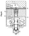
- Figure 8 shows a known variable displacement type compressor.
- a housing 101 defines a crank chamber 102 and supports a drive shaft 103.
- the drive shaft 103 is driven by an engine of the vehicle.
- a swash plate 104 is supported within the crank chamber 102 so that the swash plate 104 can be tilted and rotated together with the drive shaft 103.
- a regulating ring 105 is attached to the drive shaft 103 to limit the minimum inclination of the swash plate 104.
- a spring 106 urges the drive shaft 103 in one axial direction to prevent axial play in the drive shaft 103.
- the housing 101 includes a plurality of cylinder bores 107, a suction chamber 108 and a discharge chamber 109.
- a piston 110 is located within each cylinder bore 107.
- Each piston 110 is coupled to the swash plate 104.
- a valve plate 111 partitions the cylinder bore 107 from the suction chamber 108 and the discharge chamber 109.
- the suction chamber 108 and the discharge chamber 109 are connected through an external refrigerant circuit.
- each piston 110 draws refrigerant gas in the suction chamber 108 into the cylinder bore 107 through a suction port 111a and a suction valve 111b of the valve plate 111.
- Each piston 110 compresses gas within the cylinder bore 107 and discharges gas into the discharge chamber 109 through a discharge port 111c and a discharge valve 111d of the valve plate 111.
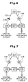
- a displacement control structure as shown diagrammatically in Figure 6, is employed to control the displacement of the compressor of Fig. 8.
- the crank chamber 102 and the suction chamber 108 are connected with each other through a bleed passage 112.
- the discharge chamber 109 and the crank chamber 102 are connected with each other through a supply passage 113.
- An inlet control valve 114 is formed by a solenoid valve. The inlet control valve 114 selectively opens or closes the supply passage 113 in accordance with an electric signal supplied from an outside controller.
- a restriction 115 is provided midway in the bleed passage 112.
- the inlet control valve 114 closes the supply passage 113, so that the high pressure gas is prevented from flowing from the discharge chamber 109 to the crank chamber 102. Since gas can always flow from the crank chamber 102 to the suction chamber 108 through the bleed passage 112, the pressure in the crank chamber 102 decreases. As a result, the swash plate 104 moves to the maximum angle of inclination, and the displacement is maximized.
- the inlet control valve 114 opens the supply passage 113, and high pressure gas is supplied from the discharge chamber 109 to the crank chamber 102. Since the flow rate of gas from the crank chamber 102 to the suction chamber 108 through the bleed passage 112, which has the restriction 115, is relatively small, if the supply passage 113 is opened, the pressure of the crank chamber 102 is increased. As a result, the swash plate 104 moves to the minimum angle of inclination, and the displacement is minimized.
- crank chamber 102 and the suction chamber 108 are always connected through the bleed passage 112. Accordingly, if the inlet control valve 114 opens the supply passage 113, high pressure gas from the discharge chamber 109 continuously flows into the suction chamber 108 through the crank chamber 102. Thus, some of the compressed gas is needlessly pumped into the suction chamber 108. Thus, the efficiency of the compressor is reduced.
- the restriction 115 be made to have small opening so that the amount of gas discharged from the crank chamber 102 to the suction chamber 108 is very small.
- the inlet control valve 114 when the inlet control valve 114 is opened, the pressure of the crank chamber 102 is abruptly increased and becomes too high. The result is that the swash plate 104 abruptly moves toward the minimum angle of inclination and sharply collides with the regulating ring 105. This collision causes a noise. Further, the impact of swash plate 104 pushes the drive shaft 103 in the rearward axial direction (to the right in Fig. 8). As a result, the drive shaft 103 moves against the force of the spring 106. The movement of the drive shaft 103 causes various problems such as the collision of the pistons 110 with the valve plate 111.
- the restriction 115 provided on the bleed passage 112 shown in Figure 6 is replaced with a solenoid driven outlet control valve 116.
- the outlet control valve 116 closes the bleed passage 112
- the outlet control valve 116 opens the bleed passage 112.
- the pressure in the crank chamber 102 reaches a predetermined level when the inlet control valve 114 is open and the outlet control valve 116 is closed, the bleed passage 112 is opened by the outlet control valve 116.
- the pressure of the crank chamber 102 is thus limited.
- each of the outlet control valve 116 and the inlet control valve 114 requires independent external control. This imposes a heavy duty on the computer that controls the valves 114 and 116. Furthermore, each of the valves 114, 116 must be provided with a wire from the computer. This complicates the wiring, the assembly and the installation and thus increases the overall costs.
- the inlet control valve 114 opens the supply passage 113, and gas from the discharge chamber 109 is continuously supplied to the crank chamber 102. Therefore, even if the pressure in the crank chamber 102 is temporarily reduced by opening the outlet control valve 116, the pressure of the crank chamber will again increase to an excessive level when the outlet control valve 116 is closed. Consequently, the outlet control valve 116 is repetitively opened and closed, and gas from the discharge chamber 109 is intermittently allowed to flow to the suction chamber 108 through the crank chamber 102. For this reason, the efficiency of the compressor of Figure 7 is only marginally better than that of the compressor of Figure 6.
- a variable displacement compressor comprises: a crank chamber, the pressure of which is a crank pressure, wherein the displacement of the compressor is varied in accordance with the crank pressure; a suction pressure zone, the pressure of which is a suction pressure; a discharge pressure zone, the pressure of which is a discharge pressure; a bleed passage for connecting the crank chamber to the suction pressure zone; a supply passage for connecting the crank chamber to the discharge pressure zone, wherein the supply passage includes a fixed restriction; a buffer chamber located in the supply passage between the fixed restriction and the crank chamber; a first valve element for selectively opening and closing the supply passage between the buffer chamber and the crank chamber; an actuator for actuating the first valve element in response to an external command; a second valve element for selectively opening and closing the bleed passage, wherein the crank pressure and the suction pressure are applied to the second valve element; and a transmission member for transmitting movement of the first valve element to the second valve element, wherein the transmission member causes the second valve element to open the bleed passage
- variable displacement type compressor of Figure 1 As shown in Figure 1, a front housing member 11 is coupled to the front end of a cylinder block 12. A rear housing member 13 is coupled to the rear end of the cylinder block 12 through a valve plate 14. A crank chamber 15 is defined between the front housing member 11 and the cylinder block 12.
- a drive shaft 16 is supported by the front housing 11 and the cylinder block 12 so that the drive shaft 16 passes through the crank chamber 15.
- the drive shaft 16 is coupled to an external power source, which in this embodiment is a vehicle engine Eg, by way of a clutch mechanism C such as an electromagnetic clutch.
- a rotating support 17 is fixed on the drive shaft 16 within the crank chamber 15.
- a swash plate 18, or drive plate is supported to slide along the surface of the drive shaft 16 and to incline with respect to the axis L of the drive shaft 16.
- a hinge mechanism 19 is provided between the rotating support 17 and the swash plate 18.
- the swash plate 18 is coupled to the rotating support 17 through the hinge mechanism 19.
- the hinge mechanism 19 rotates the swash plate 18 integrally with the drive shaft 16.
- the hinge mechanism 19 also guides the sliding movement and tilting movement of the swash plate 18 relative to the drive shaft 16.
- the angle of inclination of the swash plate 18 increases as the swash plate 18 approaches the rotating support 17, and the angle of inclination decreases as the swash plate 18 approaches the cylinder block 12.
- a limit ring 20 is attached to the drive shaft 16 between the swash plate 18 and the cylinder block 12.
- the swash plate 18 When the swash plate 18 abuts against the limit ring 20, the swash plate 18 is minimally inclined. Also, when the swash plate 18 abuts against the rotating support 17, the swash plate 18 is maximally inclined.
- a plurality of cylinder bores 21 are formed in the cylinder block 12.
- a single-headed piston 22 is accommodated within each cylinder bore 21.
- Each piston 22 is coupled to the periphery of the swash plate 18 with a pair of shoes 23.
- the swash plate 18 converts the rotational motion of the drive shaft 16 into a reciprocating motion of the pistons.
- a support spring 30, which is a helical spring in this embodiment, urges the drive shaft 16 axially toward the front housing member 11, which prevents axial play in the drive shaft.
- a suction chamber 24, the pressure of which is referred to as the suction pressure, and a discharge chamber 25, the pressure of which is referred to as the discharge pressure, are formed independently in the rear housing 13.
- the suction chamber 24 and the discharge chamber 25 are connected with each other through an external refrigerant circuit.
- a suction port 26, a suction valve 27, a discharge port 28 and a discharge valve 29 are formed in the valve plate 14 for each cylinder bore 21.
- Each piston 22 draws gas in the suction chamber 24 to the corresponding cylinder bore 21 through the corresponding suction port 26 and suction valve 27. Also, each piston 22 compresses gas in the corresponding cylinder bore 21 to a predetermined pressure level and then discharges the gas to the discharge chamber 25 through the corresponding discharge port 28 and discharge valve 29.
- a bleed passage 31 connects the crank chamber 15 and the suction chamber 24.
- a supply passage 32 connects the discharge chamber 25 and the crank chamber 15.
- a fixed restriction 33 is provided in the supply passage 32. The fixed restriction 33 is formed by reducing the diameter of the supply passage 32 at one location.
- a solenoid driven displacement control valve 35 is attached to the rear housing member 13 so that the displacement control valve 35 regulates the bleed passage 31 and the supply passage 32.
- the bleed passage 31 and the supply passage 32 share a common passage 60, which is located between the control valve 35 and the crank chamber 15.
- the common passage 60 forms an upstream portion of the bleed passage 31 and a downstream portion of the supply passage 32.
- a buffer chamber 34 is formed in the supply passage 32 between the fixed restriction 33 and the control valve 35.
- the buffer chamber 34 is connected with the discharge chamber 25 through the fixed restriction 33.
- the buffer chamber 34 has a volume equal to or smaller than the volume of the crank chamber 15.
- the displacement control valve 35 selectively opens or closes the bleed passage 31 based on an electric command supplied from an external controller. Further, the displacement control valve 35 selectively opens or closes the supply passage 32 between the buffer chamber 34 and the crank chamber 15.
- the displacement control valve 35 includes a valve housing 41 and a solenoid 42 coupled to each other.
- a first valve chamber 43 is defined at the lower end of the valve housing 41.
- a first valve element 44 is located in the first valve chamber 43 so that the first valve element 44 can be moved axially.
- a first valve opening 45 extends axially in the valve housing.
- the first valve opening 45 is connected to the first valve chamber 43.
- a first spring 46 is accommodated in the first valve chamber 43. The first spring 46 urges the first valve element 44 in a direction to open the first valve opening 45, that is, away from the first valve opening 45.
- the first valve chamber 43 is connected to the discharge chamber 25 through an upstream part of the supply passage 32.
- a second valve chamber 47 is defined at the upper end of the valve housing 41.
- a second valve element 48 is located in the second valve chamber 47 so that the second valve element 48 can move axially.
- the second valve opening 49 is formed in the valve housing 41 to extend axially.
- the second valve opening 49 is connected to the second valve chamber 47.
- a second spring 58 is accommodated in the second valve chamber 47. The second spring 58 urges the second valve element 48 to close the second valve opening 49.
- the second valve chamber 47 is connected with the suction chamber 24 through the downstream side of the bleed passage 31.
- the solenoid 42 or electromagnetic actuator, has a plunger chamber 50.
- a fixed core 51 is located between the plunger chamber 50 and the first valve chamber 43.
- a plunger 52 is located in the plunger chamber 50 and can reciprocate.
- a cylindrical coil 53 is provided to surround the fixed core 51 and the plunger 52.
- a first guide opening 54 is formed in the fixed core 51.
- the first guide opening connects the plunger chamber 50 with the first valve chamber 43.
- a first rod 55 is fitted into the first guide opening 54 and is movable in the first guide opening 54. As shown in Fig. 2, an annular clearance exists between the first rod 55 and the wall of the first guide opening 54.
- the lower end of the first rod 55 is fixed to the plunger 52.
- the upper end of the first rod 55 is fixed to the first valve element 44.
- the plunger 52 and the first valve element 44 are locked to each other through the first rod 55.
- the first valve opening 45 and the second valve opening 49 are coaxial and are connected with each other to form a single second guide opening 56.
- a transmission member, or a second rod 57 occupies the second guide opening 56.
- the outer diameter of the second rod 57 is smaller than the inner diameter of the second guide opening 56 as shown.
- the lower end of the second rod 57 is fixed to the first valve element 44.
- the upper end of the second rod 57 is not fixed to the second valve element 48, however, the second spring 58 urges the second valve element 48 to abut against the upper end of the second rod 57.
- the first valve element 44 and the second valve element 48 are coupled with each other through the second rod 57.
- a port 59 is formed in the valve housing 41.
- the port 59 communicates with the second guide opening 56 and is perpendicular to the second guide opening 56.
- the port 59 communicates with the crank chamber 15 through the common passage 60.
- the first valve chamber 43, the first valve opening 45 and the port 59 form part of supply passage 32.
- the second valve chamber 47, the second valve opening 49 and the port 59 form part of the bleed passage 31.
- a cabin temperature setting device 61 for setting a target temperature in the passenger compartment of the vehicle, a cabin temperature sensor 62 for detecting the temperature of the passenger compartment, a drive circuit 63 for energizing the coil 53 of the displacement control valve 35 and the clutch mechanism C are connected to a controller X.
- the controller X includes a computer.
- the controller X connects the engine Eg with the compressor by engaging the clutch mechanism C, which drives the compressor.
- the controller X supplies signals to the drive circuit 63 instructing the drive circuit 63 to supply or stop electric current to the coil 53, in accordance with various information, which includes the set temperature of the cabin temperature setting device 61 and the temperature detected by the cabin temperature sensor 62.
- the controller X supplies to the drive circuit 63 with a command supply current to the coil 53.
- the coil 53 is supplied with current from the drive circuit 63, an electromagnetic attraction is produced between the fixed core 51 and the plunger 52, which moves the plunger 52 toward the fixed core 51. Consequently, as shown in Figure 2, the first rod 55, the first valve element 44, the second rod 57 and the second valve element 48 are integrally moved up against the force exerted by the first spring 46 and the second spring 58.
- the first valve element 44 closes the first valve opening 45 while the second valve element 48 opens the second valve opening 49.
- the first valve opening 45 is closed by the first valve element 44, and the buffer chamber 34 is isolated from the crank chamber 15. Further, high pressure gas from the discharge chamber 25 flows into the buffer chamber 34 through the fixed restriction 33. Therefore, if the compressor is continuously driven at maximum displacement, the pressure of the buffer chamber 34 will increase to approximately the pressure of the discharge chamber 25.
- the controller X commands the drive circuit 63 to stop supplying current to the coil 53.
- the electromagnetic attraction force between the fixed core 51 and the plunger 52 vanishes. Consequently, as shown in Figure 3, the plunger 52, the first rod 55, the first valve element 44, the second rod 57 and the second valve element 48 are moved downward by the first spring 46 and the second spring 58.
- the first valve element 44 opens the first valve opening 45 while the second valve element 48 closes the second valve opening 49.
- the buffer chamber 34 Since the buffer chamber 34 is downstream of the fixed restriction 33, if the first valve opening 45 is opened, the buffer chamber 34 supplies a large amount of high pressure gas to the crank chamber 15. Therefore, regardless of the fixed restriction 33, the opening of the first valve opening causes a rapid increase in the pressure of the crank chamber 15. Consequently, the displacement rapidly and responsively decreases.
- the second valve element 48 is driven by the solenoid 42 but is also a differential pressure regulating valve that moves in response to the difference between the pressure of the crank chamber 15 and the pressure of the suction chamber 24.
- the displacement control valve 35 is arranged to include only one solenoid 42 for driving two valve elements 44 and 48. This arrangement simplifies the structure of the control valve 35 and the method of controlling the control valve 35. This reduces the duty load on the controller X and simplifies the wiring of the controller X, the control valve 35, and the drive circuit 63.
- the bleed passage 31 and the supply passage 32 share the common passage 60 between the control valve 35 and the crank chamber 15. This simplifies the design of the compressor compared with an arrangement in which the passages 31 and 32 are separate. Of course, the passages 31 and 32 may be separate.
- the first valve element 44 opens the first valve opening 45 while the second valve element 48 closes the second valve opening 49 to minimize the displacement. Therefore, if the coil 53 fails to operate due to a problem such as wire breakage, the compressor is driven at the minimum displacement. Therefore, even if the engine Eg is driven at a high speed, the compressor is protected from excessive loads.
- the present invention can be varied as follows:
- the fixed restriction may be formed by a pin placed in the supply passage 32.
- the pin has a diameter that is smaller than that of the supply passage. This simplifies the manufacture of the supply passage 32.
- the first valve element 44 may close the first valve opening 45 while the second valve element 48 opens the second valve opening 49 to cause the compressor to operate at the maximum displacement when the coil 53 is not supplied with current. According to this variation, if the coil 53 fails to operate, the compressor operates at maximum displacement. This allows the compressor to handle a large cooling load.
- the plunger 50 may be driven by an actuator other than the solenoid 42.
- the plunger 50 may be driven hydraulically or pneumatically.
- a variable displacement compressor includes a bleed passage (31) for connecting a crank chamber (15) to a suction chamber (24) and a supply passage (32) for connecting the crank chamber (15) to a discharge chamber (25).
- the supply passage (32) includes a fixed restriction (33).
- a buffer chamber (34) is located in the supply passage (32) between the fixed restriction (33) and the crank chamber (15).
- a first valve element (44) selectively opens and closes the supply passage (32) between the buffer chamber (34) and the crank chamber (15).
- a solenoid (42) actuates the first valve element (44) in response to a current.
- a second valve element (48) opens and closes the bleed passage (31). When the first valve element (44) closes the supply passage (32), the second valve element (48) opens the bleed passage (31).
- the second valve element (48) When the first valve element (44) is open, the second valve element (48) operates in accordance with the difference between the pressure in the crank chamber (15) and the pressure in the suction chamber. In this compressor, the displacement can be changed rapidly, the efficiency of the compressor is relatively high, and the pressure in the crank chamber (15) is limited.
Landscapes
- Engineering & Computer Science (AREA)
- Mechanical Engineering (AREA)
- General Engineering & Computer Science (AREA)
- Compressors, Vaccum Pumps And Other Relevant Systems (AREA)
- Control Of Positive-Displacement Pumps (AREA)
Applications Claiming Priority (2)
| Application Number | Priority Date | Filing Date | Title |
|---|---|---|---|
| JP3289399 | 1999-02-10 | ||
| JP11032893A JP2000230480A (ja) | 1999-02-10 | 1999-02-10 | 可変容量型圧縮機の容量制御構造 |
Publications (2)
| Publication Number | Publication Date |
|---|---|
| EP1028253A2 true EP1028253A2 (de) | 2000-08-16 |
| EP1028253A3 EP1028253A3 (de) | 2001-01-03 |
Family
ID=12371578
Family Applications (1)
| Application Number | Title | Priority Date | Filing Date |
|---|---|---|---|
| EP00102697A Withdrawn EP1028253A3 (de) | 1999-02-10 | 2000-02-09 | Struktur eines Verdrängungskontrollsystems für einen variablen Verdrängungskompressor |
Country Status (2)
| Country | Link |
|---|---|
| EP (1) | EP1028253A3 (de) |
| JP (1) | JP2000230480A (de) |
Family Cites Families (5)
| Publication number | Priority date | Publication date | Assignee | Title |
|---|---|---|---|---|
| SG30647G (en) * | 1991-01-28 | 1995-09-01 | Sanden Corp | Slant plate type compressor with variable displacement mechanism |
| JPH0599136A (ja) * | 1991-10-23 | 1993-04-20 | Sanden Corp | 可変容量型斜板式圧縮機 |
| JP3131015B2 (ja) * | 1992-04-03 | 2001-01-31 | 株式会社鷺宮製作所 | 電磁式制御弁 |
| US6010312A (en) * | 1996-07-31 | 2000-01-04 | Kabushiki Kaisha Toyoda Jidoshokki Seiksakusho | Control valve unit with independently operable valve mechanisms for variable displacement compressor |
| EP0864749B1 (de) * | 1997-03-14 | 2004-06-02 | Kabushiki Kaisha Toyota Jidoshokki | Elektromagnetisches Regelventil |
-
1999
- 1999-02-10 JP JP11032893A patent/JP2000230480A/ja active Pending
-
2000
- 2000-02-09 EP EP00102697A patent/EP1028253A3/de not_active Withdrawn
Non-Patent Citations (1)
| Title |
|---|
| None |
Also Published As
| Publication number | Publication date |
|---|---|
| JP2000230480A (ja) | 2000-08-22 |
| EP1028253A3 (de) | 2001-01-03 |
Similar Documents
| Publication | Publication Date | Title |
|---|---|---|
| US6010312A (en) | Control valve unit with independently operable valve mechanisms for variable displacement compressor | |
| US6352416B1 (en) | Device and method for controlling displacement of variable displacement compressor | |
| US5785502A (en) | Control apparatus for variable displacement compressor | |
| EP0748937B1 (de) | Hubsteuervorrichtung für einen Kolbenverdichter mit variabelem Hub ohne Kupplung | |
| EP1098091B1 (de) | Durchflussregelung eines Kompressors in einem Kühlkreislauf | |
| US6481976B2 (en) | Control valve and variable capacity type compressor having control valve | |
| EP1103721B1 (de) | Klimaanlage und Steuerventil in einem variablen Verdrängungskompressor | |
| EP1835177A2 (de) | Verstellungsregelventil eines verstellbaren Verdichters | |
| KR100270472B1 (ko) | 제어 밸브 | |
| US6234763B1 (en) | Variable displacement compressor | |
| EP1138946B1 (de) | Regelventil für einen Verdichter variabler Verdrängung | |
| KR19980064124A (ko) | 가변용량 압축기용 제어밸브 | |
| EP0854288B1 (de) | Regelventil für einen Verdichter mit veränderlicher Förderleistung und Verfahren zur Herstellung | |
| EP0881387A2 (de) | Taumelscheibenkompressor mit veränderlicher Förderleistung ohne Kupplung | |
| US6290468B1 (en) | Variable displacement compressor | |
| US6672844B2 (en) | Apparatus and method for controlling variable displacement compressor | |
| JP3948432B2 (ja) | 容量可変型圧縮機の制御装置 | |
| US7523620B2 (en) | Displacement control mechanism for variable displacement compressor | |
| EP1179680A2 (de) | Kontrollventil für einen verstellbaren Taumelscheibenkompressor | |
| US6241483B1 (en) | Variable displacement compressor | |
| EP1024286A2 (de) | Kontrollventil für einen verstellbaren Taumelscheibenverdichter | |
| US4730987A (en) | Variable delivery compressor | |
| KR20010106179A (ko) | 공조장치 | |
| EP1302345A2 (de) | Fahrzeugklimaanlage | |
| EP1375918A1 (de) | Vorrichtung zur Regelung eines Kompressors |
Legal Events
| Date | Code | Title | Description |
|---|---|---|---|
| PUAI | Public reference made under article 153(3) epc to a published international application that has entered the european phase |
Free format text: ORIGINAL CODE: 0009012 |
|
| 17P | Request for examination filed |
Effective date: 20000209 |
|
| AK | Designated contracting states |
Kind code of ref document: A2 Designated state(s): DE FR IT |
|
| AX | Request for extension of the european patent |
Free format text: AL;LT;LV;MK;RO;SI |
|
| PUAL | Search report despatched |
Free format text: ORIGINAL CODE: 0009013 |
|
| AK | Designated contracting states |
Kind code of ref document: A3 Designated state(s): AT BE CH CY DE DK ES FI FR GB GR IE IT LI LU MC NL PT SE |
|
| AX | Request for extension of the european patent |
Free format text: AL;LT;LV;MK;RO;SI |
|
| AKX | Designation fees paid |
Free format text: DE FR IT |
|
| STAA | Information on the status of an ep patent application or granted ep patent |
Free format text: STATUS: THE APPLICATION IS DEEMED TO BE WITHDRAWN |
|
| 18D | Application deemed to be withdrawn |
Effective date: 20020903 |