EP1028342B1 - Dispositif pour basculer un élément optique autour de deux axes perpendiculaires - Google Patents
Dispositif pour basculer un élément optique autour de deux axes perpendiculaires Download PDFInfo
- Publication number
- EP1028342B1 EP1028342B1 EP00102490A EP00102490A EP1028342B1 EP 1028342 B1 EP1028342 B1 EP 1028342B1 EP 00102490 A EP00102490 A EP 00102490A EP 00102490 A EP00102490 A EP 00102490A EP 1028342 B1 EP1028342 B1 EP 1028342B1
- Authority
- EP
- European Patent Office
- Prior art keywords
- axis
- adjustment
- inner ring
- coupling rods
- outer ring
- Prior art date
- Legal status (The legal status is an assumption and is not a legal conclusion. Google has not performed a legal analysis and makes no representation as to the accuracy of the status listed.)
- Expired - Lifetime
Links
- 230000003287 optical effect Effects 0.000 title claims description 37
- 230000008878 coupling Effects 0.000 claims description 69
- 238000010168 coupling process Methods 0.000 claims description 69
- 238000005859 coupling reaction Methods 0.000 claims description 69
- 239000007787 solid Substances 0.000 claims description 5
- 230000005540 biological transmission Effects 0.000 claims description 4
- 238000013461 design Methods 0.000 description 3
- 238000012937 correction Methods 0.000 description 2
- 238000004519 manufacturing process Methods 0.000 description 2
- 241000238631 Hexapoda Species 0.000 description 1
- 238000013459 approach Methods 0.000 description 1
- 238000005452 bending Methods 0.000 description 1
- 230000015572 biosynthetic process Effects 0.000 description 1
- 238000011161 development Methods 0.000 description 1
- 230000018109 developmental process Effects 0.000 description 1
- 238000010586 diagram Methods 0.000 description 1
- 238000006073 displacement reaction Methods 0.000 description 1
- 230000000694 effects Effects 0.000 description 1
- 238000001459 lithography Methods 0.000 description 1
- 239000004065 semiconductor Substances 0.000 description 1
- 239000000725 suspension Substances 0.000 description 1
- 230000007704 transition Effects 0.000 description 1
- 238000013519 translation Methods 0.000 description 1
Images


Classifications
-
- G—PHYSICS
- G03—PHOTOGRAPHY; CINEMATOGRAPHY; ANALOGOUS TECHNIQUES USING WAVES OTHER THAN OPTICAL WAVES; ELECTROGRAPHY; HOLOGRAPHY
- G03F—PHOTOMECHANICAL PRODUCTION OF TEXTURED OR PATTERNED SURFACES, e.g. FOR PRINTING, FOR PROCESSING OF SEMICONDUCTOR DEVICES; MATERIALS THEREFOR; ORIGINALS THEREFOR; APPARATUS SPECIALLY ADAPTED THEREFOR
- G03F7/00—Photomechanical, e.g. photolithographic, production of textured or patterned surfaces, e.g. printing surfaces; Materials therefor, e.g. comprising photoresists; Apparatus specially adapted therefor
- G03F7/70—Microphotolithographic exposure; Apparatus therefor
- G03F7/708—Construction of apparatus, e.g. environment aspects, hygiene aspects or materials
- G03F7/70808—Construction details, e.g. housing, load-lock, seals or windows for passing light in or out of apparatus
- G03F7/70825—Mounting of individual elements, e.g. mounts, holders or supports
-
- G—PHYSICS
- G02—OPTICS
- G02B—OPTICAL ELEMENTS, SYSTEMS OR APPARATUS
- G02B7/00—Mountings, adjusting means, or light-tight connections, for optical elements
- G02B7/003—Alignment of optical elements
-
- G—PHYSICS
- G02—OPTICS
- G02B—OPTICAL ELEMENTS, SYSTEMS OR APPARATUS
- G02B7/00—Mountings, adjusting means, or light-tight connections, for optical elements
- G02B7/02—Mountings, adjusting means, or light-tight connections, for optical elements for lenses
- G02B7/023—Mountings, adjusting means, or light-tight connections, for optical elements for lenses permitting adjustment
Definitions
- the invention relates to a device for tilting an optical Elements about at least one axis, in particular one Lens, according to the preamble of claim 1.
- DD 278 207 Al shows a socket with adjustment elements provided, on which individually composed optical elements in one Filling tube are arranged.
- the adjustment elements exist of two immediately adjacent, one inside the other and independent rotatable washers. By turns of the washers, which form a pair of wedge rings, can be a defined inclination of the optical axis of the optical element to adjust. In this way, the optical axes individual optical elements with high accuracy for mechanical Axis of a lens. With a Device of this type is achieved that the optical axis of a single optical element that matches the optical Axis of the lens in which the optical element is installed is, does not match, can be aligned.
- the misalignment of an optical axis of an optical element can e.g. due to manufacturing inaccuracies or uneven flanges an outer ring.
- the adjustment elements according to DD 278 207 Al there are deviations the optical axes of optical elements from the axis of the Objectives, but not for lenses for semiconductor lithography correct the required high accuracy because the adjustment with the pair of wedge rings is fraught with friction and thus so-called stick-slip and hysteresis effects occur, which result in an "about” correction. So it always will set a slightly larger adjustment as desired.
- the optical element however, it is not decoupled from deformation from the outer frame, so that tension and deformation on the flange on the optical Element to be transferred.
- the present invention has for its object a To improve the device of the type mentioned at the outset in such a way that an optical element very precisely at least around an axis, in particular, however, be pivoted about two axes can, although the optical element compared to its version or its outer ring should be decoupled from deformation Device itself, however, with respect to the z axis (optical axis) should be relatively stiff.
- this task is characterized by Part of claim 1 features solved.
- the inner ring that carries the optical element is over total six couplers connected to the socket or the outer ring.
- Four couplers serve as so-called support couplers such that the inner ring is only perpendicular to the two can rotate tilting axes facing each other.
- the two others Couplings that act as adjusting couplers support each Torques about the two tilt axes (x-axis and y-axis) and at the same time serve to adjust and adjust the Tilt angle.
- Through the coupling is the bearing of the inner ring thus statically determined, at the same time in this way a decoupling of the deformation of the inner ring compared to Outer ring is reached. Since the two tilt axes are vertical stand to each other, the tilting movements do not affect each other each other, which is why corrections when adjusting in one Direction is not necessary.
- the device can be however in the z-axis due to the inclination or Inclination of the support coupling at an angle ⁇ to the z axis relatively stiff, depending on the size of the angle Set ⁇ .
- the design of the support coupling can be any. So can for this e.g. Solid-state joints, ball joints or the like be used, the connection with the inner ring and the outer ring each via a joint or an adjustable or compliant connection can be made.
- tilting manipulators known from practice which are based on a Three-point or hexapod bearing of the inner ring in the outer ring based, experiences the optical element when tilted because of the a tilt offset with respect to the optical axis by tilting around other tilt axes again must be highlighted. Since in the device according to the invention the two tilt axes the optical axis of the optical In this case, no element can be cut Axial misalignment when tilting.
- tilting movements continue to influence each other, because the tilt axes are not perpendicular to each other.
- Tilt axes perpendicular to each other so no mutual The tilting movements are influenced.
- the adjustment range is selected so that the Tilt angle between the inner ring and outer ring, which at a Outer ring deformation, e.g. by screwing on the outer ring on an uneven surface, due to the statically determined storage arises, can be corrected.
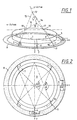
- Each of the six paddocks has a joint 10, with which the associated coupling with the inner ring 7 and another joint 11, with which also the associated coupling with the outer ring 8 or an adjustment mechanism (see Figure 5, reference numerals 21-27), which is held by the outer ring 8, is connected.
- the Joints 10 and 11 can be used as ball joints, solid body joints or be formed in a similar manner.
- the inner ring 7 By connecting the inner ring 7 to the outer ring 8 Over the six couplers, the inner ring 7 is of manufacturing inaccuracies of the outer ring 8 or the socket and of its Deformations decoupled. At the same time, the six However, couple an adjustment around two perpendicular to each other Axes, namely the x-axis and the y-axis become. This is done in the following way:
- the inner ring 7 is formed by the four support couplers 1, 2, 3 and 4 worn on the outer ring 8 such that for the inner ring 7 only two degrees of freedom, namely around the x-axis and the y axis. These two axes represent the tilt axes
- the y-axis is the axis of rotation or tilting thereby through the intersection points 12 and 13, their connecting line represents the y-axis.
- the intersection 12 results for this purpose from the extension line 14 of the support coupling 1 the extension line 15 of the support coupling 2 and the intersection 13 results from the extension line 16 of the support coupling 3 with the extension line 17 of the support coupling 4.
- the axis of rotation or tilt which is 90 ° lies, namely the x-axis, by means of a connecting line formed by the intersection points 18 and 19.
- the intersection 18 results from the extension line 15 of the Support coupling 2 with the extension line 16 of the support coupling 3.
- the intersection 19 results from the extension line 14 of the support belt 1 with the extension line 17 of the support belt 4.
- the Tilt angle of the inner ring 7 about the y-axis of rotation can by a Moving the adjusting coupling 5 in the x direction with respect to the outer ring 8 can be set.
- the adjusting coupling 6 supports the torques about the x-axis and is located on the y-axis of the outer ring 8. Through a displacement of the adjusting coupling 6 in the y direction compared to the Outer ring 8 can the tilt angle of the inner ring 7 about the x-axis can be set.
- An arrangement angle ⁇ describes the arrangement of the support coupling 1 to 4 to the inner ring 7 in plan view (see figure 2).
- the arrangement angle ⁇ is the angle between the tangent the starting point of the support coupling 1, 2, 3 or 4 on the inner ring 7 and the support coupling projected into the xy plane.
- the Arrangement angle ⁇ of the support coupling 1, 2, 3 and 4 is thus the axial position of the tilt axes relative to each other.
- FIGs 2 to 6 is a top view in principle a possible configuration for the support coupling 1, 2, 3 and 4 and the coupling 5 and 6 shown.
- the support couplers 1, 2, 3, 4 are always on straight lines from 45 ° to the inner ring.
- these are Support coupling 1, 2, 3 and 4 each via the joint 11 with the Outer ring 8 and the joint 10 connected to the inner ring.
- the Figure 4 shows a section along the line IV-IV of Figure 3 with an embodiment of the support coupling 1 to 4 as solid-state joints in an enlarged view.
- Hinge points 10, 11 can be seen.
- the two couplers 5 and 6 can either by one direct attack on these can be adjusted or by adjusting screws 20 (see schematic diagram in Figure 5), which parallel guidance with a gear ratio the adjustment of the coupling 5 and 6 in the direction of the x or. Act on the y-axis (see arrows).
- the parallel guide shown only has one Transmission lever 21 on which the adjusting screw 20 engages.
- the translation lever 21 is articulated with one approach 22 of an angle lever 23 connected, which in turn with his other leg than the drive leg 24 with a setting plate 25 the coupling 5 or 6 is connected.
- the pitch angle 23 is via an articulated connection 26 to the outer ring 8 connected.
- About another leg 27 is the Setting plate 25 again articulated to the outer ring 8.
- the setting angle 23, the setting plate 25 and the leg 27 form a parallel guide for the joint 11 of the adjusting coupling 5 or 6.
- adjustment movements of the Set screw 20 in the direction of the arrow to shift the Coupling 5 in the x direction and the coupling 6 in the y direction. This way you get a large adjustment range with the adjusting screw 20 a very fine shift or Adjustment of the coupling 5 and 6 in the x and y direction.
- Figure 6 shows an enlarged section of the section VI-VI 3 shows a structural design of the adjusting coupling 5 or 6 with solid-state joints 10, 11.
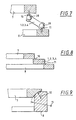
- FIGS. 7 to 9 show some configurations of support couplers, which, however, can only be seen as an example.
- the support coupling 1, 2, 3 or 4 shown in FIG. 7 is provided with low-friction ball joints 28 and 29, which the Form joints 10 and 11.
- FIG. 8 shows an embodiment of the support coupling 1 to 4 with Solid-state joints 10 and 11, as in the embodiment according to Figures 1 to 6 are shown by Formation of elastic, thin transition points between the one-piece inner ring 7 and outer ring 8.
- FIG. 9 shows a special type, with the support coupling 1 to 4 through spherical surfaces between the inner ring 7 and the outer ring 8 are formed or assume their function.
- the kinematic Hinge points 10 and 11 of this connection are located on the centers of curvature of the spherical surfaces.
- the device each four support coupling 1 to 4, the starting points are evenly distributed around the circumference on the inner ring 7, and two adjusting brackets 5 and 6, which enclose an angle of 90 °.
- the optical element can be used a mirror or another optical element is also provided that is decoupled from deformation.
Landscapes
- Physics & Mathematics (AREA)
- General Physics & Mathematics (AREA)
- Optics & Photonics (AREA)
- Health & Medical Sciences (AREA)
- Engineering & Computer Science (AREA)
- Environmental & Geological Engineering (AREA)
- Epidemiology (AREA)
- Public Health (AREA)
- Mounting And Adjusting Of Optical Elements (AREA)
- Pivots And Pivotal Connections (AREA)
- Lens Barrels (AREA)
Claims (10)
- Dispositif pour basculer un élément optique (9), en particulier une lentille, autour d'au moins un axe, l'élément optique (9) étant porté par une bague intérieure (7) et relié à une monture ou à une bague extérieure (8) par l'intermédiaire d'au moins trois points de portée, dans lequel les basculements de l'élément optique (9) peuvent être réglés autour des axes s'étendant perpendiculairement à l'axe optique (axe z), et dans lequel il est prévu comme éléments d'ajustement plusieurs biellettes (1-6), dont certaines, constituant des biellettes de support (1-4), donnent appui à la bague intérieure (7) sur la bague extérieure (8) ou sur la monture de telle manière que la bague intérieure (7) puisse tourner seulement autour de deux axes de basculement (axe x, axe y) perpendiculaires entre eux, tandis que deux autres biellettes, jouant le rôle de biellettes de réglage (5, 6) forment le point de réaction pour les couples autour des axes de basculement perpendiculaires entre eux et que les angles de basculement peuvent être réglés par déplacement des biellettes de réglage (5, 6), caractérisé en ce que les axes des biellettes de support (1-4) sont inclinés sur l'axe optique d'un angle d'attaque (α) non nul.
- Dispositif selon la revendication 1, caractérisé en ce que les biellettes de support (1-4) sont disposées de manière que les axes de basculement (axe x, axe y) soient situés sur différents côtés de l'objet.
- Dispositif selon la revendication 2, caractérisé en ce que les biellettes de support (1-4) attaquent la bague intérieure (7) tangentiellement.
- Dispositif selon l'une des revendications 1 à 3, caractérisé en ce que les biellettes de support (1-4) comportent chacune deux articulations (10, 11), par l'intermédiaire desquelles sont réalisées les liaisons entre la bague intérieure (7) et la bague extérieure (8) ou la monture.
- Dispositif selon la revendication 4, caractérisé en ce que les articulations (10, 11) sont constituées par des articulations à corps solides.
- Dispositif selon la revendication 4, caractérisé en ce que les articulations (10, 11) sont constituées par des articulations à rotule (28, 29).
- Dispositif selon la revendication 4, caractérisé en ce que les articulations (10, 11) sont pourvues de surfaces sphériques sur la bague intérieure (7) et sur la bague extérieure (8).
- Dispositif selon l'une des revendications 1 à 7, caractérisé en ce que les biellettes de réglage (5, 6) sont pourvues d'organes de réglage (15) par lesquels il est possible de modifier les rapports de transmission de la course de déplacement.
- Dispositif selon la revendication 8, caractérisé en ce que des vis de réglage (15), qui attaquent les biellettes de réglage (5, 6) par l'intermédiaire de leviers de transmission (21-27), sont prévues comme organes de réglage.
- Dispositif selon la revendication 9, caractérisé en ce que l'extrémité des biellettes de réglage (5, 6) qui n'est pas reliée à la bague intérieure (7) est reliée à la bague extérieure (8) par l'intermédiaire d'un guidage parallèle (24, 25, 27) et les leviers de transmission (21, 22) attaquent le guidage parallèle.
Applications Claiming Priority (2)
| Application Number | Priority Date | Filing Date | Title |
|---|---|---|---|
| DE19905779A DE19905779A1 (de) | 1999-02-12 | 1999-02-12 | Vorrichtung zum Kippen eines Gegenstandes um wenigstens eine Achse, insbesondere eines optischen Elementes |
| DE19905779 | 1999-02-12 |
Publications (2)
| Publication Number | Publication Date |
|---|---|
| EP1028342A1 EP1028342A1 (fr) | 2000-08-16 |
| EP1028342B1 true EP1028342B1 (fr) | 2003-08-27 |
Family
ID=7897224
Family Applications (1)
| Application Number | Title | Priority Date | Filing Date |
|---|---|---|---|
| EP00102490A Expired - Lifetime EP1028342B1 (fr) | 1999-02-12 | 2000-02-05 | Dispositif pour basculer un élément optique autour de deux axes perpendiculaires |
Country Status (4)
| Country | Link |
|---|---|
| US (1) | US6271976B1 (fr) |
| EP (1) | EP1028342B1 (fr) |
| JP (1) | JP2000235134A (fr) |
| DE (2) | DE19905779A1 (fr) |
Families Citing this family (23)
| Publication number | Priority date | Publication date | Assignee | Title |
|---|---|---|---|---|
| DE19905779A1 (de) * | 1999-02-12 | 2000-08-17 | Zeiss Carl Fa | Vorrichtung zum Kippen eines Gegenstandes um wenigstens eine Achse, insbesondere eines optischen Elementes |
| JP4945845B2 (ja) * | 2000-03-31 | 2012-06-06 | 株式会社ニコン | 光学素子保持装置、鏡筒及び露光装置並びにマイクロデバイスの製造方法。 |
| DE10039712A1 (de) * | 2000-08-14 | 2002-02-28 | Zeiss Carl | Vorrichtung zum Verstellen der Lage zweier Bauelemente zueinander |
| JP4770090B2 (ja) * | 2000-08-18 | 2011-09-07 | 株式会社ニコン | 光学素子保持装置、鏡筒及び露光装置並びにマイクロデバイスの製造方法 |
| EP1312965B1 (fr) * | 2000-08-18 | 2007-01-17 | Nikon Corporation | Dispositif de maintien d'element optique |
| DE10051706A1 (de) * | 2000-10-18 | 2002-05-02 | Zeiss Carl | Vorrichtung zur Lagerung eines optischen Elementes |
| DE10100546A1 (de) | 2001-01-08 | 2002-07-11 | Zeiss Carl | Vorrichtung zur Verstellung eines optischen Elementes in einem Objektiv |
| DE10106650B4 (de) * | 2001-02-12 | 2006-11-02 | Klaus Hoffmann | Binokulare optische Vorrichtung, insbesondere elektronische Brille, mit einer elektronischen Kamera zur automatischen Scharfeinstellung einschließlich Korrektur verschiedener Sehfehler |
| JP2002287023A (ja) | 2001-03-27 | 2002-10-03 | Nikon Corp | 投影光学系、該投影光学系を備えた投影露光装置及び投影露光方法 |
| TWI244119B (en) * | 2001-11-07 | 2005-11-21 | Asml Netherlands Bv | Lithographic apparatus and device manufacturing method |
| JP4134566B2 (ja) * | 2002-02-04 | 2008-08-20 | 株式会社ニコン | 光学要素の位置決め方法及び装置、投影光学系、並びに露光装置 |
| JP4665759B2 (ja) * | 2003-06-06 | 2011-04-06 | 株式会社ニコン | 光学素子保持装置、鏡筒、露光装置、及びデバイスの製造方法 |
| DE102004025832A1 (de) * | 2004-05-24 | 2005-12-22 | Carl Zeiss Smt Ag | Optikmodul für ein Objektiv |
| WO2005064382A1 (fr) * | 2003-12-25 | 2005-07-14 | Nikon Corporation | Appareil destine a supporter un element optique, cylindre, appareil d'exposition et procede de fabrication d'un dispositif |
| DE102004052154B4 (de) * | 2004-10-24 | 2006-10-05 | Berliner Elektronenspeicherring-Gesellschaft für Synchrotronstrahlung mbH | Rotationslager zur hochgenau einstellbaren Winkelposition eines optischen Spiegels |
| WO2007056595A1 (fr) * | 2005-11-09 | 2007-05-18 | Thomson Licensing | Regleur de couture optique |
| JP5165699B2 (ja) * | 2007-02-28 | 2013-03-21 | コーニング インコーポレイテッド | 一点の周囲に回動可能な光学マウント |
| FR2925963B1 (fr) * | 2008-01-02 | 2010-08-13 | Briot Int | Appareil de palpage d'une monture de verres optiques et procede associe |
| JP5588358B2 (ja) * | 2008-02-29 | 2014-09-10 | コーニング インコーポレイテッド | キネマティック光学マウント |
| DE102009025309B4 (de) * | 2009-06-15 | 2016-12-22 | Toptica Photonics Ag | Kinematischer Halter |
| DE102013204305A1 (de) | 2013-03-13 | 2014-09-18 | Carl Zeiss Smt Gmbh | Anordnung zur Aktuierung wenigstens eines Elementes in einem optischen System |
| DE102017203079A1 (de) * | 2017-02-24 | 2018-08-30 | Carl Zeiss Smt Gmbh | Lithographieanlage und verfahren |
| DE102024203031A1 (de) | 2024-04-02 | 2025-10-02 | Carl Zeiss Smt Gmbh | Vorrichtung, Halteeinrichtung, Anordnung, System und Verfahren zur Halterung eines optischen Elements; Lithografiesystem |
Family Cites Families (8)
| Publication number | Priority date | Publication date | Assignee | Title |
|---|---|---|---|---|
| US3917385A (en) | 1973-09-19 | 1975-11-04 | Rockwell International Corp | Simplified micropositioner |
| US3989358A (en) | 1974-11-21 | 1976-11-02 | Kms Fusion, Inc. | Adjustable micrometer stage |
| US4298248A (en) | 1980-05-16 | 1981-11-03 | The United States Of America As Represented By The Secretary Of The Navy | Pivotal support with independent adjusting elements and locking means |
| DD278207A1 (de) | 1988-12-19 | 1990-04-25 | Zeiss Jena Veb Carl | Fassung mit justierelementen |
| US5353167A (en) * | 1992-07-22 | 1994-10-04 | The United States Of America As Represented By The United States Department Of Energy | Mirror mount |
| US5986827A (en) * | 1998-06-17 | 1999-11-16 | The Regents Of The University Of California | Precision tip-tilt-piston actuator that provides exact constraint |
| DE19901295A1 (de) * | 1999-01-15 | 2000-07-20 | Zeiss Carl Fa | Optische Abbildungsvorrichtung, insbesondere Objektiv, mit wenigstens einem optischen Element |
| DE19905779A1 (de) * | 1999-02-12 | 2000-08-17 | Zeiss Carl Fa | Vorrichtung zum Kippen eines Gegenstandes um wenigstens eine Achse, insbesondere eines optischen Elementes |
-
1999
- 1999-02-12 DE DE19905779A patent/DE19905779A1/de not_active Withdrawn
-
2000
- 2000-01-27 US US09/490,890 patent/US6271976B1/en not_active Expired - Lifetime
- 2000-02-05 EP EP00102490A patent/EP1028342B1/fr not_active Expired - Lifetime
- 2000-02-05 DE DE50003407T patent/DE50003407D1/de not_active Expired - Fee Related
- 2000-02-07 JP JP2000028740A patent/JP2000235134A/ja active Pending
Also Published As
| Publication number | Publication date |
|---|---|
| DE50003407D1 (de) | 2003-10-02 |
| EP1028342A1 (fr) | 2000-08-16 |
| DE19905779A1 (de) | 2000-08-17 |
| US6271976B1 (en) | 2001-08-07 |
| JP2000235134A (ja) | 2000-08-29 |
Similar Documents
| Publication | Publication Date | Title |
|---|---|---|
| EP1028342B1 (fr) | Dispositif pour basculer un élément optique autour de deux axes perpendiculaires | |
| EP1020751B1 (fr) | Dispositif d'imagerie optique, en particulier objectif, avec au moins un élement optique | |
| DE102004025832A1 (de) | Optikmodul für ein Objektiv | |
| DE10344178B4 (de) | Halte- und Positioniervorrichtung für ein optisches Element | |
| EP1245982B1 (fr) | Appareil pour monter un élément optique dans un appareillage optique | |
| EP1160609B1 (fr) | Appareil pour le positionnement précis d'un composant optique | |
| DE69901021T2 (de) | Vorrichtung zur montage und lagekorrektur eines elementes, wie eines spiegels von einem weltraumteleskop | |
| DE102009037135B4 (de) | Haltevorrichtung für ein optisches Element | |
| DE102009005954B4 (de) | Dämpfungsvorrichtung | |
| EP1164397A1 (fr) | Monture d'objectif, en particulier pour un objectif de projetion en lithographie semiconducteur | |
| WO2010037778A1 (fr) | Éléments de soutien pour un élément optique | |
| WO2008022797A1 (fr) | Équipement d'éclairage de projection et système optique | |
| EP1015931A2 (fr) | Systeme optique, notamment installation d'eclairage pour projection servant a la microlithographie | |
| EP2843454A1 (fr) | Bloc optique doté d'un support avec des unités de liaison ayant une flexibilité dirigée | |
| DE102005057860A1 (de) | Objektiv, insbesondere Projektionsobjektiv für die Halbleiterlithographie | |
| EP3296787A1 (fr) | Module optique comprenant des surfaces optiques basculantes | |
| DE102007030579B4 (de) | Lateral verstellbare Fassung für optische Elemente | |
| DE4122015A1 (de) | Spiegellagerung fuer den primaerspiegel eines teleskops | |
| EP1412692B1 (fr) | Lunette de visee | |
| EP0431114A1 (fr) | Portique fixe pour un appareil de mesure de coordonnees de haute precision. | |
| EP1657577B1 (fr) | Support pivotant permettant un réglage de haute précision de la position angulaire d'un objet | |
| DE60201429T2 (de) | In dem schatten eines spiegels aufgestelltes montage- und justiergerät für diesen spiegel und mit diesem gerät versehenes optisches system | |
| DE102020134653B3 (de) | Justierbarer Optikhalter für ein optisches Element | |
| DE102019112224A1 (de) | Abstützung eines optischen Elements | |
| WO2016119779A1 (fr) | Monture optique pourvue d'au moins une unité de serrage à vis de tension |
Legal Events
| Date | Code | Title | Description |
|---|---|---|---|
| PUAI | Public reference made under article 153(3) epc to a published international application that has entered the european phase |
Free format text: ORIGINAL CODE: 0009012 |
|
| AK | Designated contracting states |
Kind code of ref document: A1 Designated state(s): DE FR NL |
|
| AX | Request for extension of the european patent |
Free format text: AL;LT;LV;MK;RO;SI |
|
| 17P | Request for examination filed |
Effective date: 20001114 |
|
| AKX | Designation fees paid |
Free format text: DE FR NL |
|
| 17Q | First examination report despatched |
Effective date: 20020617 |
|
| RIC1 | Information provided on ipc code assigned before grant |
Ipc: 7G 02B 7/00 A Ipc: 7G 02B 7/02 B Ipc: 7G 02B 7/182 B |
|
| RTI1 | Title (correction) |
Free format text: DEVICE FOR PIVOTING AN OPTICAL ELEMENT AROUND TWO ORTHOGONAL AXES |
|
| GRAH | Despatch of communication of intention to grant a patent |
Free format text: ORIGINAL CODE: EPIDOS IGRA |
|
| GRAS | Grant fee paid |
Free format text: ORIGINAL CODE: EPIDOSNIGR3 |
|
| GRAA | (expected) grant |
Free format text: ORIGINAL CODE: 0009210 |
|
| AK | Designated contracting states |
Designated state(s): DE FR NL |
|
| PG25 | Lapsed in a contracting state [announced via postgrant information from national office to epo] |
Ref country code: NL Free format text: LAPSE BECAUSE OF FAILURE TO SUBMIT A TRANSLATION OF THE DESCRIPTION OR TO PAY THE FEE WITHIN THE PRESCRIBED TIME-LIMIT Effective date: 20030827 Ref country code: FR Free format text: LAPSE BECAUSE OF FAILURE TO SUBMIT A TRANSLATION OF THE DESCRIPTION OR TO PAY THE FEE WITHIN THE PRESCRIBED TIME-LIMIT Effective date: 20030827 |
|
| REF | Corresponds to: |
Ref document number: 50003407 Country of ref document: DE Date of ref document: 20031002 Kind code of ref document: P |
|
| NLV1 | Nl: lapsed or annulled due to failure to fulfill the requirements of art. 29p and 29m of the patents act | ||
| PLBE | No opposition filed within time limit |
Free format text: ORIGINAL CODE: 0009261 |
|
| STAA | Information on the status of an ep patent application or granted ep patent |
Free format text: STATUS: NO OPPOSITION FILED WITHIN TIME LIMIT |
|
| 26N | No opposition filed |
Effective date: 20040528 |
|
| EN | Fr: translation not filed | ||
| PGFP | Annual fee paid to national office [announced via postgrant information from national office to epo] |
Ref country code: DE Payment date: 20080219 Year of fee payment: 9 |
|
| PG25 | Lapsed in a contracting state [announced via postgrant information from national office to epo] |
Ref country code: DE Free format text: LAPSE BECAUSE OF NON-PAYMENT OF DUE FEES Effective date: 20090901 |